
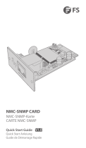
L2+ MANAGED INDUSTRIAL SWITCH
L2+ MANAGED INDUSTRIELLER SWITCH
SWITCH INDUSTRIEL MANAGEABLE L2+
Quick Start Guide V1.0
Quick-Start Anleitung
Guide de Démarrage Rapide
IES3110-8TF Switch
P1 FAULT
RESET
P2
9
9
10
10
7
5
3
1 2
4
6
8
R.O.RING
1G/2.5G Link/Act 1G/2.5G
SFP
Link/Act
IES3110-8TF
Link
Act
1000
Act
Link

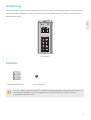
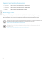
Introduction
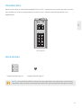
Accessories
IES3110-8TF
Thank you for choosing IES3110-8TF Managed Switch. This guide is designed to familiarize you with
the layout of the switch and describes how to deploy the switch in your network.
1
EN
Mounting Bracket x2 M3 Screw x4
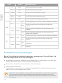
NOTE: IES3110-8TF switch has dust plugs delivered with it. Keep the dust plugs properly
and use them to protect idle ports.
P1 FAULT
RESET
P2
9
9
10
10
7
5
3
1 2
4
6
8
R.O.RING
1G/2.5G Link/Act 1G/2.5G
SFP
Link/Act
IES3110-8TF
Link
Act
1000
ActLink

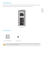
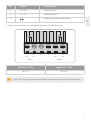
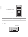
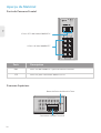
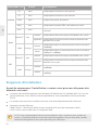
2x 100/1000/2500BASE-X SFP Ports
1
Max. fault loading: 24V,1A
DC Input: 12-48V,1.25A max.
AC Input: 24V~,0.7A max.
23456
V1+ V1
PWR1
V2+ V2
PWR2
Fault
P1 FAULT
RESET
P2
9
9
10
10
7
5
3
1 2
4
6
8
R.O.RING
1G/2.5G Link/Act 1G/2.5G
SFP
Link/Act
IES3110-8TF
Link
Act
1000
ActLink
Front Panel Ports
Upper Panel
Hardware Overview
8x 10/100/1000BASE-T Ports
2
EN
Ports Description
10/100/1000BASE-T ports for Ethernet connection
SFP ports for 100M/1G/2.5G connection
RJ45
SFP
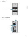
Grounding Point
Terminal Block Connector

Rear Panel
3
EN
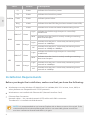
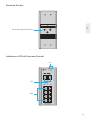
Front Panel LEDs
DIN-rail Mounting Kit
P1 FAULT
RESET
P2
9
9
10
10
7
5
3
1 2
4
6
8
R.O.RING
1G/2.5G Link/Act 1G/2.5G
SFP
Link/Act
IES3110-8TF
Link
Act
1000
ActLink
SFP
RJ45
SYS

4
EN
Installation Requirements
NOTE: It is recommended to use Internet Explorer 8.0 or above to access the switch. If the
web interface of the Industrial Managed Switch is not accessible, please turn off the
anti-virus software or firewall and then try it again.
Indicates the Switch has power.
Indicates the Switch has power.
LEDs DescriptionStatus
P1
P2
Green
Light
Blink
Orange
Light
Off
Green
Green
Green
Green
Green
Indicates power failure.
Indicates that the ERPS Ring has been created successfully.
Indicates that Switch has been enabled to Ring Owner.
SYSTEM
RJ45
Fault
Ring
R.O.
Indicates the link through that port is successfully
established.
Indicates that the Switch is actively sending or receiving
data over that port.
Indicates that the port is successfully connecting to the
network at 1000Mbps.
Indicates that the port is successfully connecting to the
network at 10Mbps or 100Mbps.
LINK/ACT
1000
Green
Light
Blink
Orange
Light
Off
SFP
Indicates the link through that port is successfully
established.
Indicates that the Switch is actively sending or receiving
data over that port.
Indicates that the port is successfully connecting to the
network at 1000Mbps.
Indicates that the port is successfully connecting to the
network at 100Mbps.
LINK/ACT
1000
Before you begin the installation, make sure that you have the following:
Workstations running Windows XP/2003/Vista/7/8/10/2008, MAC OS X or later, Linux, UNIX, or
other platforms are compatible with TCP/IP protocols.
Workstations are installed with Ethernet NIC (Network Interface Card).
Ethernet Port Connection
Network cables -- Use standard network (UTP) cables with RJ45 connectors.
The above PC is installed with Web browser.

5
EN
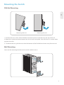
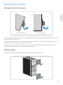
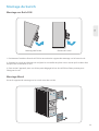
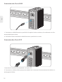
1. Position the unit in front of the DIN-Rail and hook the mount bracket over the top of the rail.
2. Rotate the switch downward towards the rail to lock it into place. You will know it is secure when
you hear the click.
3. To remove the unit, pull down to clear the bottom of the DIN-Rail and rotate away from the rail.
Mounting the Switch
Screw on the mounting bracket on the switch with M3 screws.
DIN-Rail Mounting
Wall Mounting
Mounting the unit Releasing the unit

1
Max. fault loading: 24V,1A
DC Input: 12-48V,1.25A max.
AC Input: 24V~,0.7A max.
23456
V1+ V1
PWR1
V2+ V2
PWR2
Fault
1
Max. fault loading: 24V,1A
DC Input: 12-48V,1.25A max.
AC Input: 24V~,0.7A max.
23456
V1+ V1
PWR1
V2+ V2
PWR2
Fault
123456
V1+ V1
PWR1
V2
+
V2
PWR2
Fault
6
EN
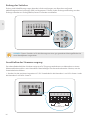
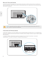
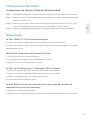
The Upper Panel of the switch indicates an AC/DC inlet power socket and consists of one terminal
block connector within 6 contacts. Please follow the steps below to insert the power wire.
1. Insert positive/negative AC or DC power wires into Contacts 1 and 2 for Power 1, or Contacts 5
and 6 for Power 2.
Connecting the Power
NOTE: This product is intended to be mounted to a well-grounded mounting surface such
as a metal panel.
Grounding and wire routing help limit the effects of noise due to electromagnetic interference (EMI).
Run the ground connection from the ground screw to the grounding surface prior to connecting
devices.
Grounding the Switch
1
DC Input: 12-48V ,1.25A max.
AC Input: 24V~,0.7A max.
23456
V1+ V1
PWR1
V2+ V2
PWR2
Fault
12-48VDC,24VAC

7
EN
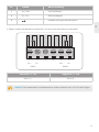
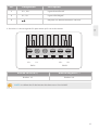
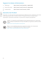
V1+ V1- V2+ V2-
PWR1 PWR2
123456
NOTE: The wire gauge for the terminal block should be in the range from 12 to 24 AWG.
Pin 2 / 6
Positive (+) Pin Negative (-) Pin
Pin 1 / 5
2. Tighten the wire-clamp screws for preventing the wires from loosening.
Live line/Positive
Null line/Negative
Requiring good ground connection
NameNo. Description
V1+, V2+
V1-, V2-
1
2
3

P1 FAULT
RESET
P2
9
9
10
10
7
5
3
1 2
4
6
8
R.O.RING
1G/2.5G Link/Act 1G/2.5G
SFP
Link/Act
IES3110-8TF
Link
Act
1000
Act
Link
P1 FAULT
RESET
P2
9
9
10
10
7
5
3
1 2
4
6
8
R.O.RING
1G/2.5G Link/Act 1G/2.5G
SFP
Link/Act
IES3110-8TF
Link
Act
1000
Act
Link
8
EN
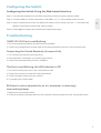
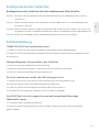
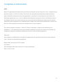
1. Plug the compatible SFP transceiver into the SFP port.
2. Connect a fiber optic cable to the fiber transceiver. Then connect the other end of the cable to
another fiber device.
Connecting the SFP Ports
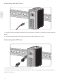
1. Connect an Ethernet cable to the RJ45 port of a camera, outdoor AP, computer or other network
device.
2. Connect the other end of the Ethernet cable to the RJ45 port of the switch.
Connecting the RJ45 Ports

9
EN
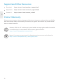
Step 1: Connect the computer to any RJ45 port of the switch using the network cable.
Step 2: Set the IP address of the computer to 192.168.1.x ("x" is any number from 2 to 255).
Step 3: Open a web browser, enter the default IP address of the switch 192.168.1.1, and enter the
default username and password, admin/admin.
Step 4: Click Login to display the web-based configuration page.
100M/1G/2.5G Port is not Working
1. Ensure the optical module and cable have no problem.
2. Check if the configuration at both ends of the communication device is auto or forced rate.
Connecting the Switch Remotely Unsuccessfully
1. Test network connectivity through ping.
2. If the network is reachable, try restarting the switch.
3. Check if the corresponding service is enabled.
The Port is not Working, the LED Indicator is Off
1. Ensure the switch ports are in the no shutdown state.
2. Check if the switch can read the DDM information.
3. Check if the port speed setting is correct.
4. Try looping the switch cable.
Configuring the Switch
Troubleshooting
Configuring the Switch Using the Web-based Interface
RJ45 port is not in connectivity or it is erroneous in receiving/
transmitting frames
1. Replace the twisted pair cable.
2. Check that the port configuration has the common working mode with the connected switch.

10
EN
FS ensures our customers that any damage or faulty items due to our workmanship, we will offer a
free return within 30 days from the day you receive your goods. This excludes any custom made
items or tailored solutions.
Support and Other Resources
Product Warranty
Warranty: IES3110-8TF switch enjoy 5 years limited warranty against defect in materials
or workmanship. For more details about warranty, please check at
https://www.fs.com/policies/warranty.html
Return: If you want to return item(s), information on how to return can be found at
https://www.fs.com/policies/day_return_policy.html
5
Download https://www.fs.com/products_support.html
Help Center https://www.fs.com/service/fs_support.html
Contact Us https://www.fs.com/contact_us.html

Einführung
Zubehör
IES3110-8TF
Vielen Dank, dass Sie sich für den Managed Switch IES3100-8TF entschieden haben. Diese Anleitung
soll Sie mit dem Aufbau des Switches vertraut machen und beschreibt, wie Sie den Switch in Ihrem
Netzwerk einsetzen.
11
DE
Montagehalterung x2 M3-Schraube x4
Hinweis: Beim Switch IES3100-8TF werden Staubschutzkappen mitgeliefert. Bewahren Sie
die Staubschutzkappen ordnungsgemäß auf, und verwenden Sie sie zum Schutz
ungenutzter optischer Ports.
P1 FAULT
RESET
P2
9
9
10
10
7
5
3
1 2
4
6
8
R.O.RING
1G/2.5G Link/Act 1G/2.5G
SFP
Link/Act
IES3110-8TF
Link
Act
1000
ActLink

2x 100/1000/2500BASE-X SFP-Ports
1
Max. fault loading: 24V,1A
DC Input: 12-48V,1.25A max.
AC Input: 24V~,0.7A max.
23456
V1+ V1
PWR1
V2+ V2
PWR2
Fault
P1 FAULT
RESET
P2
9
9
10
10
7
5
3
1 2
4
6
8
R.O.RING
1G/2.5G Link/Act 1G/2.5G
SFP
Link/Act
IES3110-8TF
Link
Act
1000
ActLink
Ports an der Vorderseite
Obere Platte
Hardware-Übersicht
8x 10/100/1000BASE-T- Ports
12
DE
Ports Beschreibung
10/100/1000BASE-T Ports für Ethernet-Verbindung
SFP-Ports für 100M/1G/2,5G-Verbindung
RJ45
SFP
Erdungspunkt
Anschlussklemmen-Blockstecker

Rückplatte
13
DE
LEDs an der Vorderseite
Montagekit für DIN-Hutschiene
P1 FAULT
RESET
P2
9
9
10
10
7
5
3
1 2
4
6
8
R.O.RING
1G/2.5G Link/Act 1G/2.5G
SFP
Link/Act
IES3110-8TF
Link
Act
1000
ActLink
SFP
RJ45
SYS

14
DE
Installationsvoraussetzungen
HINWEIS: Es wird empfohlen, Internet Explorer 8.0 oder höher zu verwenden, um auf den
Switch zuzugreifen. Sollte das Webinterface des Industriellen Managed Switch nicht
erreichbar sein, schalten Sie bitte die Antivirensoftware bzw. Firewall aus und versuchen
Sie es erneut.
LEDs Status
P1
P2
Grün
Ein
Blinkt
Orange
Ein
Aus
Grün
Grün
Grün
Grün
Grün
SYSTEM
RJ45
Fehler
Ring
R.O.
LINK/ACT
1000
Grün
Ein
Blinkt
Orange
Ein
Aus
SFP
Switch wird mit Strom versorgt.
Switch wird mit Strom versorgt.
Beschreibung
Switch wird nicht mit Strom versorgt.
Der EPS-Ring wird erfolgreich erstellt.
Switch wird für den Ring Besitzer aktiviert.
Die Verknüpfungen zu den Port werden erfolgreich etabliert.
Switch kann die Daten durch den Port senden oder
erhalten.
Der Port verbindet erfolgreich mit dem Netzwerk von
100Mbps.
Der Port verbindet erfolgreich mit dem Netzwerk von
10Mbps oder 100Mbps.
Die Verknüpfungen zu den Port werden erfolgreich etabliert.
Switch kann die Daten durch den Port senden oder
erhalten.
Der Port verbindet erfolgreich mit dem Netzwerk von
1000 Mbps.
Der Port verbindet erfolgreich mit dem Netzwerk von
100Mbps.
LINK/ACT
1000
Bevor Sie mit der Installation beginnen, vergewissern Sie sich, dass Sie
über die folgenden Utensilien verfügen:
Workstations mit Windows XP/2003/Vista/7/8/10/2008, MAC OS X oder höher, Linux, UNIX, oder
anderen Plattformen, die mit TCP/IP-Protokollen kompatibel sind.
Workstations, die mit Ethernet-Netzwerkkarten installiert werden.
Ethernet Port Konnektivität
Netzwerkkabel -- Verwenden Sie Standard-Netzwerkkabel (UTP) mit RJ45-Steckverbindern.Der
obige PC ist mit einem Webbrowser installiert.

15
DE
1. Positionieren Sie das Gerät vor der DIN-Hutschiene und haken Sie die Montagehalterung über der
Oberseite der Hutschiene ein.
Montage des Switches
Schrauben Sie die Montagehalterung am Switch mit M3-Schrauben fest.
Montage für DIN-Hutschiene
Wandmontage
Gerät montieren Gerät entfernen
2. Drehen Sie den Switch nach unten in Richtung der Hutschiene, um ihn zu verriegeln. Wenn Sie ein
Klicken hören, ist der Switch fest in der Hutschiene.
3. Um das Gerät zu entfernen, ziehen Sie es nach unten, um die Unterseite der DIN-Hutschiene
freizugeben, und drehen Sie es von der Hutschiene weg.

1
Max. fault loading: 24V,1A
DC Input: 12-48V,1.25A max.
AC Input: 24V~,0.7A max.
23456
V1+ V1
PWR1
V2+ V2
PWR2
Fault
1
DC Input: 12-48V ,1.25A max.
AC Input: 24V~,0.7A max.
23456
V1+ V1
PWR1
V2+ V2
PWR2
Fault
1
Max. fault loading: 24V,1A
DC Input: 12-48V,1.25A max.
AC Input: 24V~,0.7A max.
23456
V1+ V1
PWR1
V2+ V2
PWR2
Fault
123456
V1+ V1
PWR1
V2
+
V2
PWR2
Fault
16
DE
Das obere Bedienfeld des Schalters zeigt eine DC-Eingangssteckdose an und besteht aus einem
Klemmenblockanschluss mit 6 Kontakten. Bitte befolgen Sie die nachstehenden Schritte, um das
Stromkabel einzuführen.
1. Stecken Sie die positiven/negativen AC-/DC-Stromkabel in die Kontakte 1 und 2 für Strom 1 oder
die Kontakte 5 und 6 für Strom 2.
Anschließen der Stromversorgung
HINWEIS: Dieses Produkt ist für die Montage an einer gut geerdeten Montagefläche wie
einer Metallplatte vorgesehen.
Erdung und Kabelführung tragen dazu bei, die Auswirkungen von Rauschen aufgrund
elektromagnetischer Störungen (EMI) zu begrenzen. Führen Sie die Erdungsverbindung von der
Erdungsschraube zur Erdungsfläche, bevor Sie Geräte anschließen.
Erdung des Switches
12-48VDC,24VAC

17
DE
V1+ V1- V2+ V2-
PWR1 PWR2
123456
HINWEIS: Die Drahtstärke für die Klemmleiste sollte im Bereich von 12 bis 24 AWG liegen.
Pin 2 / 6
Positive (+) Pin Negative (-) Pin
Pin 1 / 5
2. Ziehen Sie die Drahtklemmschrauben fest, um ein Lösen der Drähte zu verhindern.
Live Line/Positiv
Null Line/Negativ
Erfordert eine gute Masseanschluss
NameNr. Beschreibung
V1+, V2+
V1-, V2-
1
2
3

P1 FAULT
RESET
P2
9
9
10
10
7
5
3
1 2
4
6
8
R.O.RING
1G/2.5G Link/Act 1G/2.5G
SFP
Link/Act
IES3110-8TF
Link
Act
1000
Act
Link
P1 FAULT
RESET
P2
9
9
10
10
7
5
3
1 2
4
6
8
R.O.RING
1G/2.5G Link/Act 1G/2.5G
SFP
Link/Act
IES3110-8TF
Link
Act
1000
Act
Link
18
DE
1. Stecken Sie den kompatiblen SFP-Transceiver in den SFP-Port.
2. Schließen Sie ein Glasfaserkabel an den Glasfasertransceiver an. Schließen Sie dann das andere
Ende des Kabels an ein anderes Glasfasergerät an.
Anschließen der SFP Ports
1. Schließen Sie ein Ethernet-Kabel an den RJ45-Port von Kamera, Outdoor-AP, Computer oder
anderen Netzwerkgeräten an.
2. Schließen Sie das andere Ende des Ethernet-Kabels an den RJ45-Port des Switches an.
Anschließen der RJ45-Ports

19
DE
Schritt 1: Schließen Sie den Computer über das Netzwerkkabel an den beliebigen RJ45-Port des
Switches an.
Schritt 2: Stellen Sie die IP-Adresse des Computers auf 192.168.2.x ein ("x" ist eine beliebige Zahl
zwischen 2 und 255).
Schritt 3: Öffnen Sie einen Browser, geben Sie die Standard-IP-Adresse des Switches 192.168.2.1 ein,
und geben Sie den Standardbenutzernamen und das Standardkennwort admin/admin ein.
Schritt 4: Klicken Sie auf Login, um die webbasierte Konfigurationsseite anzuzeigen.
100M/1G/2,5G-Port funktioniert nicht
1. Stellen Sie sicher, dass das optische Modul und das Kabel keine Probleme haben.
2. Prüfen Sie, ob die Konfiguration an beiden Enden des Kommunikationsgeräts automatisch oder
erzwungen ist.
Fehlgeschlagener Fernanschluss des Switches
1. Testen Sie die Netzwerkkonnektivität durch Ping.
2. Wenn das Netzwerk erreichbar ist, versuchen Sie, den Switch neu zu starten.
3. Prüfen Sie, ob der entsprechende Dienst aktiviert ist.
Der Port funktioniert nicht, die LED-Anzeige ist aus
1. Vergewissern Sie sich, dass die Ports des Switches nicht heruntergefahren sind.
2. Prüfen Sie, ob der Switch die DDM-Informationen lesen kann.
3. Prüfen Sie, ob die Geschwindigkeitseinstellung des Ports korrekt ist.
4. Versuchen Sie, das Kabel des Switches in einer Schleife zu verlegen.
Der RJ45-Port ist nicht angeschlossen oder empfängt/überträgt
fehlerhaft Frames
1. Tauschen Sie das Twisted Pair Kabel aus.
2. Prüfen Sie, ob die Konfiguration des Ports mit dem angeschlossenen Switch im gleichen
Modus arbeitet.
Konfigurieren des Switsches
Fehlerbehebung
Konfigurieren des Switches über die webbasierte Schnittstelle
Seite wird geladen ...
Seite wird geladen ...
Seite wird geladen ...
Seite wird geladen ...
Seite wird geladen ...
Seite wird geladen ...
Seite wird geladen ...
Seite wird geladen ...
Seite wird geladen ...
Seite wird geladen ...
Seite wird geladen ...
Seite wird geladen ...
Seite wird geladen ...
-
 1
1
-
 2
2
-
 3
3
-
 4
4
-
 5
5
-
 6
6
-
 7
7
-
 8
8
-
 9
9
-
 10
10
-
 11
11
-
 12
12
-
 13
13
-
 14
14
-
 15
15
-
 16
16
-
 17
17
-
 18
18
-
 19
19
-
 20
20
-
 21
21
-
 22
22
-
 23
23
-
 24
24
-
 25
25
-
 26
26
-
 27
27
-
 28
28
-
 29
29
-
 30
30
-
 31
31
-
 32
32
-
 33
33


in anderen Sprachen
- English: FS IES3110-8TF User guide
- français: FS IES3110-8TF Mode d'emploi
Verwandte Artikel
-
FS IES3100-8TF Benutzerhandbuch
-
FS SFP10G Benutzerhandbuch
-
FS FVFL-204 Benutzerhandbuch
-
FS IPC201-2M-T Benutzerhandbuch
-
FS S3410 Series Benutzerhandbuch
-
FS IPC201-2M-B Benutzerhandbuch
-
FS AP-N505 Benutzerhandbuch
-
FS S1900-16TP Benutzerhandbuch
-
FS IES5100-24TF Benutzerhandbuch
-
 FS NMC-SNMP Benutzerhandbuch

Andere Dokumente
-
MOB IES3110 Series Benutzerhandbuch
-
Renkforce GH-4200E+ Bedienungsanleitung
-
Korenix JetNet 4510f Series Quick Installation Manual
-
Westermo MCI-211G Benutzerhandbuch
-
Westermo MDI-110-F3G Benutzerhandbuch
-
FS COM AC-7072 Benutzerhandbuch
-
Korenix JetNet 5428G Series Quick Installation Manual
-
Intellinet 508346 Bedienungsanleitung
-
SonicWALL SWS14-24 Schnellstartanleitung
-
Eks DL422 Bedienungsanleitung