Celestron 22470 Benutzerhandbuch
- Kategorie
- Teleskope
- Typ
- Benutzerhandbuch

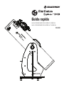
Quick Setup Guide
#22470 STARSENSE EXPLORER 8” DOBSONIAN
#22471 STARSENSE EXPLORER 10” DOBSONIAN
ENGLISH

2 I ENGLISH
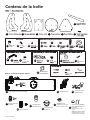
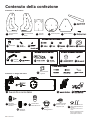
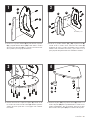
Bottom plateFront panel Top plateLeft side panel
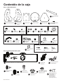
Box 1 – Dobsonian Base
Box 2 – Optical Tube Assembly
Side supports
(x2)
AZIMUTH PIVOT BOLT ASSEMBLY
FEET ASSEMBLY
Rubber bumper
Crescent
wrenches (x2)
Hex keys (x2)
Screwdriver
A1
StarSense dock
P
Optical tube assembly with dust cover
OStarPointer
red dot finderscope
Q
E
Base assembly
screws (x22)
F
Eyepiece rack Rack
screws (x2)
K1 K2 Altitude bearing
cylinders (x4)
L1 Bearing
screws (x4)
L2
M
Base
handle
J1 Handle
screws (x2)
J2
Feet (x3) Bolt Nut Steel
washers
(x2)
H1 H2 H3 Hollow
plastic
cylinder
H4 Teflon
washer
H5
G1 Feet
screws (x3)
G2 Feet screw
covers (x3)
G3
Right side panel
A2 B C D
HANDLE ASSEMBLY EYEPIECE RACK ASSEMBLY ALTITUDE BEARING ASSEMBLY
INCLUDED TOOLS
Altitude
tensioning knob
N1
Cosmetic knob
N2
25mm Omni
Plössl eyepiece
R1
2" focuser
extension tube
S
2"-to-1.25" eyepiece
adapter with 1.25"
cover cap
T
NOTE: For collimating your telescope’s
optics, refer to the full instruction
manual at celestron.com
Collimation cap with
2mm and 2.5mm hex keys*
U
*2.5mm hex key included with 8” Dob only
What’s in the Box

ENGLISH I3
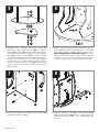
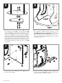
1. Connect the side supports (E) to the left side panel (A1) and
right side panel (A2) using 6 of the base assembly screws (F).
The supports go on the on the same side of the panels as the
Celestron logos.
2. Connect the side panels (A1 & A2) to the front panel (B) using
6 of the base assembly screws (F). Make sure the Celestron
logos on the side panels face outward and the small spot mark
on the face of the front panel faces inward.
A1
E
F
F
F
B
A1
3. Connect the assembly to the top plate (C) using 10 of the base
assembly screws (F). Orient the top plate so the side with the
logo faces upward.
4. Attach the 3 feet (G1) to the bottom plate (D) using the 3 feet
screws (G2). Thread the screws fi rmly into the predrilled pilot
holes. Once installed, press the feet screw covers (G3) onto the
ends of the feet.
F
C
D
G1
G2
G3
A2
A2
4
2
3
1
Spot Mark

4 I ENGLISH
5. Connect the assembly to the bottom plate (D). Place one of the
steel washers (H3) and the plastic cylinder (H4) onto the bolt
(H1). Then, insert the bolt through the central hole in the bottom
plate. Next, place the Tefl on washer (H5) over the plastic
cylinder (H4) now protruding from the bottom plate. Take the
assembled base and lower it onto the bottom plate so that the
plastic cylinder goes through the central hole in the top plate.
Now, place the remaining steel washer (H3) on the end of the
bolt protruding from the top plate. Thread the nut (H2) onto
the bolt.
7. Install the base handle (J1) onto the front panel (B) using the
2 handle screws (J2).
6. Use the two crescent wrenches to tighten the nut onto the bolt.
Hold the head of the bolt stationary with one crescent wrench
while using the other crescent wrench to tighten the nut.
DO NOT OVERTIGHTEN THE NUT! With some force, you
should still be able to move the steel washer underneath the
nut with your fi ngers. If the washer cannot be moved with your
fi ngers, slightly loosen the nut.
8. Install the eyepiece rack (K1) onto the front panel (B) using the
2 rack screws (K2). Note: If you want to remove the rack after it
has been installed, simply pull it upwards.
J1 K1
K21
B
J2
H2
H3
H4
D
H5
H3
H1
6
8
5
7

ENGLISH I5
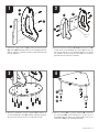
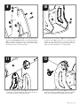
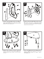
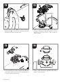
9. Install the altitude bearing cylinders (L1) onto the left and right
side panels (A1 & A2) with the altitude bearing screws (L2).
The bearings go on the interior surfaces of the side panels. The
end of the bearing with no bevel on it should be fl ush to the
surface of the panel.
11. Place the optical tube assembly (O) onto the assembled
Dobsonian base. The side hubs on the tube should sit on the
altitude bearing cylinders on the base.
10. Attach the rubber bumper (M) to the interior surface of the
front panel (B). There is a small spot on the front panel that
indicates where to place the rubber bumper. Remove the
adhesive backing from the bumper and press the bumper fi rmly
onto the spot.
12. Install the altitude tensioning knob (N1) through the slot in the
left side panel (A1) and into the threaded insert in the center of
the side hub on the optical tube assembly.
L1
O
N1 A1
MB
L2
A1
A2
10
12
9
11

6 I ENGLISH
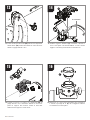
13. Install the cosmetic knob (N2) through the slot in the right side
panel (A2) and into the threaded insert in the center of the side
hub on the optical tube assembly.
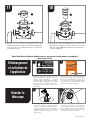
14. Install the StarSense dock (P). First, loosen the 2 thumbscrews
on the StarSense base on the tube. Insert the dock into the
base, and then retighten the thumbscrews.
N2
A2
P
1413
15. Install the StarPointer red dot fi nderscope (Q) onto the
optical tube assembly. First, loosen the thumbscrew on the
fi nderscope holder. Insert the base of the StarPointer into the
holder and tighten the thumbscrew.
16. Loosen the thumbscrews on the end of the focuser and
insert the 2” extension tube (S) into the focuser. Retighten
the thumbscrews.
Q
S
1615
THUMB SCREWS

ENGLISH I7
17. Loosen the thumbscrews on the 2” extension tube (S)
now installed in the focuser and insert the 2”-to-1.25”
eyepiece adapter (T). Retighten the thumbscrews on the
2” extension tube.
Your StarSense Explorer Dobsonian is now fully assembled and ready to be used.
18. Loosen the thumbscrews on the 2”-to-1.25” eyepiece
adapter (T) now installed in the focuser, place the 25mm
Omni Plössl eyepiece (R1) into the adapter, and retighten the
thumbscrews on the adapter.
S
T
T
R1
Downloading and
Activating the App
1. Before you take your telescope outside,
download the StarSense Explorer app to your
mobile device. Search for “Celestron StarSense
Explorer” in the Apple App Store or Google Play.
The app is large, so we recommend downloading
it while connected to Wi-Fi.
Download the app from the
before your first observing session
.
or
When prompted, enter the unique unlock code below to
enable telescope control on your device.
2. Once you have downloaded the app, locate the
orange postcard in your telescope box. Launch
the app. When prompted, enter the activation
code on the postcard to activate the app. Your
code will unlock up to 5 devices.
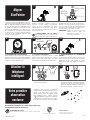
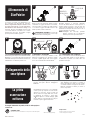
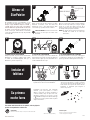
1. The StarSense Dobsonian telescope moves
freely in altitude (up-and-down) and azimuth
(left-to-right). Simply move the tube by
pushing it in the desired direction. You can use
the knob handle at the front of the telescope
for a hand grip.
2. If the altitude motion moves too freely, or the
telescope moves up or down with no force being
applied tighten the altitude tensioning knob.
Conversely, if it takes much force to move the
telescope upwards or downwards, then loosen
the knob.
Moving the
Telescope
22
1817
1
1 2
2

8 I ENGLISH
2. CENTER THE TARGET IN THE EYEPIECE
Look through the telescope using the 25mm
eyepiece. Move the telescope until the object you
chose lies in the center of the view. If the image is
blurry, gently turn the focus knobs until it comes
into sharp focus.
NOTE: The image in your telescope may appear
inverted. This is perfectly normal in an
astronomical telescope.
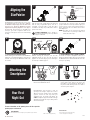
Aligning the
Finderscope
The StarPointer red dot finderscope is one of the
most important parts of your telescope. Although
the StarSense Explorer app will locate and center
objects for you, having the StarPointer properly
aligned will help during alignment of the app to
the telescope. The first time you assemble your
telescope, you need to align the finder to the
telescope’s main optics. It’s best to do this during
the day.*
1. CHOOSE A TARGET
Take the telescope outside during the day and
find an easily recognizable object, such as a
streetlight, car license plate or sign. The object
should be as far away as possible, but at least a
quarter mile away.
*SOLAR WARNING! Never attempt to
view the Sun through any telescope without
a proper solar filter!
4. ADJUST THE FINDERSCOPE
Without moving the telescope, use the two
adjustment knobs to move the red dot until it
appears over the same object you are observing in
the telescope’s 25mm eyepiece.
5. YOUR FINDERSCOPE IS NOW ALIGNED!
It should not require realignment unless it is
bumped or dropped. Now, when you look through
the StarPointer, the red dot will indicate where the
telescope is pointing.
3. LOOK THROUGH FINDERSCOPE
Pull the battery protection tab out of the StarPointer
and turn it on to maximum brightness using the on/
off knob. Look through the StarPointer and locate
the red dot.
Congratulations! Your telescope is now set
up and you are ready to explore the cosmos.
Take the telescope outside, insert your 25mm
eyepiece, remove the lens cap, insert your
smartphone into the holder, and launch the
StarSense Explorer app. The tutorial in the app
will walk you through the steps to find your first
astronomical target.
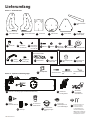
1. Remove the large cap covering the mirror on
the front of the StarSense dock.
2. Pull open the spring-loaded slider on the top
of the phone dock and set the phone into
the holder so it is flush with the bottom lip of
the phone holder. Slowly release the slider to
secure the phone in place.
25MM EYEPIECE
FOCUS KNOBS
ON/OFF KNOB
1
3 4
1
5
2
2
Aligning the
StarPointer
Attaching the
Smartphone
Your First
Night Out
For more information on this product, please visit the respective
product page on celestron.com
SOLAR WARNING:
Never attempt to view the Sun through any telescope without a proper solar filter. www.celestron.com/pages/warranty
Need assistance?
Contact Celestron Technical Support by visiting
celestron.com/pages/technical-support
04-22

Guide de confi guration rapide
#22470 STARSENSE EXPLORER 8” DOBSONIAN
#22471 STARSENSE EXPLORER 10” DOBSONIAN
FRANÇAIS

10 I FRANÇAIS
Boîte 2 – Composants du tube optique
COMPOSANTS
Amortisseurs
en caoutchouc
(x2)
(x2)
A1
P Dock StarSense
O Tube optique avec cache-poussière Q
E
F
(x2)
K1 K2
(x4)
L1 Vis
d'orientation
(x4)
L2
M
J1 Vis de
(x2)
J2
(x3)
(x2)
H1 H2 H3
H4
H5
G1 Vis des
(x3)
G2
(x3)
G3
A2 B C D
Bouton de tension
d'altitude
N1
N2 Cache décoratif
R1
S
Adaptateur pour
oculaire de 2" à 1,25"
avec cache de 1,25"
T
U
Chercheur à point
StarPointerred
Oculaire Omni
Plössl de 25 mm
Tube d'extension
de foyer 2"
Capuchon de collimation
avec clefs Allen de 2mm
et 2,5mm*
*Clef Allen de 2,5mm incluse avec Dob 8"
uniquement
REMARQUE: pour effectuer la collimation
des optiques de votre télescope, voyez le
mode d'emploi complet sur celestron.com
(x2)
Contenu de la boîte

FRANÇAIS I11
1. Attachez les supports latéraux (E) au panneaux latéraux gauche
(A1) et droit (A2) à l'aide des 6 des vis d’assemblage de la base
( F). Les supports s’installent du même côté des panneaux que
les logos Celestron.
2. Attachez les panneaux latéraux (A1 et A2) au panneau avant (B)
à l'aide des 6 vis d’assemblage de la base ( F). Assurez-vous
que les logos Celestron sur les panneaux latéraux sont orientés
vers l'extérieur et que le petit point de repère sur la face du
panneau avant est orienté vers l'intérieur.
A1
E
F
F
F
B
A1
3. Attachez l’assemblage à la plaque supérieure (C) à l'aide des 10
vis d’assemblage de la base (F). Orientez la plaque supérieure
de sorte que le côté avec le logo soit orienté vers le haut.
4. Fixez les 3 pieds (G1) à la plaque inférieure (D) à l'aide des
3vis des pieds (G2). Vissez fermement les vis dans les trous
de guidage prépercés. Une fois les pieds installés, enfoncez les
caches de vis (G3) sur les extrémités des pieds.
F
C
D
G1
G2
G3
A2
A2
4
2
3
1
Point de
repère

12 I FRANÇAIS
5. Attachez l’assemblage à la plaque inférieure (D). Placez une
des rondelles en acier (H3) et le cylindre en plastique (H4) sur
le boulon (H1). Insérez ensuite le boulon dans le trou central
de la plaque de inférieure. Ensuite, placez la rondelle en téfl on
(H5) sur le cylindre en plastique (H4) qui dépasse de la plaque
inférieure. Prenez la base assemblée et abaissez-la sur la plaque
inférieure de sorte que le cylindre en plastique passe par le trou
central de la plaque supérieure. Placez maintenant la rondelle
en acier restante (H3) sur l'extrémité du boulon dépassant de la
plaque supérieure. Vissez l'écrou (H2) sur le boulon.
7. Installez la poignée de base (J1) sur le panneau avant (B) à l'aide des
2 vis de poignée (J2).
6. Utilisez les deux clés anglaises pour serrer l'écrou sur
la vis. Maintenez la tête du boulon immobile avec une
clé anglaise tout en utilisant l'autre pour serrer l'écrou.
NE PAS SERRER EXCESSIVEMENT L'ÉCROU! La rondelle
en acier sous l'écrou doit pouvoir être poussée avec les doigts,
en appliquant un peu de force. Si la rondelle ne peut pas être
déplacée avec les doigts, desserrez légèrement l'écrou.
8. Installez le support pour oculaire (K1) sur le panneau avant (B) à
l'aide des 2 vis du rack (K2). Remarque: Si vous souhaitez retirer
le rack après l'avoir installé, il vous suffi t de tirer vers le haut.
J1 K1
K21
B
J2
H2
H3
H4
D
H5
H3
H1
6
8
5
7

FRANÇAIS I13
9. Installez les cylindres d'altitude (L1) sur les panneaux latéraux
gauche et droit (A1 et A2) à l'aide des vis d'orientation d'altitude
(L2). Les supports sont placés sur les surfaces intérieures des
panneaux latéraux. L'extrémité du support sans biseau doit être
au même niveau que la surface du panneau.
11. Placez l'assemblage du tube optique (O) sur la base Dobsonian
assemblée. Les moyeux latéraux du tube doivent reposer sur
les cylindres d'orientation d'altitude de la base.
10. Fixez l'amortisseur en caoutchouc (M) sur la surface intérieure
du panneau avant (B). Un petit point sur le panneau avant
indique où placer l'amortisseur en caoutchouc. Retirez le
support adhésif de l'amortisseur et appuyez fermement sur ce
dernier pour le fi xer fermement sur son emplacement.
12. Installez la molette de tension d'altitude (N1) dans le logement
du panneau latéral gauche (A1) et dans le pas de vis fi leté au
centre du moyeu latéral de l'assemblage du tube optique.
L1
O
N1 A1
MB
L2
A1
A2
10
12
9
11

14 I FRANÇAIS
13. Installez le cache décoratif (N2) par l'ouverture du panneau
latéral droit (A2) et dans le pas de vis fi leté au centre du moyeu
latéral de l'assemblage du tube optique.
14. Installez le dock StarSense (P). Tout d'abord, desserrez les 2
vis à main de la base StarSense sur le tube. Insérez le dock
dans la base, puis resserrez les vis à main.
N2
A2
P
1413
15. Installez le chercheur à point rouge StarPointer (Q) sur
l'assemblage du tube optique. Tout d'abord, desserrez la
vis à main sur le support du chercheur. Insérez la base du
StarPointer dans le support et serrez la vis à main.
16. Desserrez les vis à main sur l'extrémité du foyer et insérez le
tube d'extension de 2" (S) dans le foyer. Resserrez les vis à
main.
Q
S
1615
VIS MAIN

FRANÇAIS I15
17. Desserrez les vis à main du tube d'extension de 2” (S)
maintenant installé dans le porte-oculaire et insérez l'adaptateur
pour oculaire de 2” à 1,25” (T). Resserrez les vis à main sur le
tube d'extension de 2”.
Votre StarSense Explorer Dobsonian est maintenant entièrement assemblé et
prêt à être utilisé.
18. Desserrez les vis à main de l'adaptateur pour oculaire 2” à 1,25”
(T) maintenant installé dans le porte-oculaire, placez l'oculaire
Omni Plössl 25mm (R1) dans l'adaptateur et resserrez les vis
à main de l'adaptateur.
S
T
T
R1
Téléchargement
et activation de
l'application
1. Avant de sortir avec votre télescope, téléchargez
l'application StarSense Explorer sur votre
appareil mobile. Recherchez « Celestron
StarSense Explorer » dans l'App Store d'Apple
ou Google Play. L’application est de grande
taille. Nous vous recommandons donc de la
télécharger lorsque vous êtes connecté à un
réseau Wi-Fi.
Download the app from the
before your first observing session
.
or
When prompted, enter the unique unlock code below to
enable telescope control on your device.
2. Une fois que vous avez téléchargé l'application,
trouvez la carte orange dans la boîte de votre
télescope. Lancez l'application. Lorsque vous y
êtes invité, entrez le code d'activation indiqué
sur la carte pour activer l'application. Votre code
peut déverrouiller jusque 5 appareils.
1. Le télescope Dobsonian de StarSense peut
être orienté librement en altitude (de haut
en bas) et en azimut (de gauche à droite). Il
suffi t d'orienter le tube en le poussant dans
la direction souhaitée. Vous pouvez utiliser la
poignée à l'avant du télescope pour le tenir
mieux en main.
2. Si le mouvement en altitude est trop lâche ou
si le télescope se déplace vers le haut ou vers
le bas sans aucune force, serrez la molette de
tension d'altitude. À l'inverse, si l'orientation du
télescope vers le haut ou vers le bas nécessite
une grande foce, desserrez la molette.
Orienter le
télescope
22
1817
1
1 2
2

16 I FRANÇAIS
2. CENTRER LA CIBLE DANS L'OCULAIRE
Regardez dans l'oculaire de 25mm du télescope.
Orientez le télescope jusqu'à que l'objet choisi se
trouve au centre du champ de vision. Si l’image est
floue, faites doucement tourner la molette de mise
au point jusqu’à ce que l’image soit nette.
REMARQUE : l'image de votre télescope peut
sembler inversée. Cela est
parfaitement normal pour un
télescope astronomique.
Aligner le chercheur
Le chercheur à point rouge StarPointer est l'un des
composants les plus importants de votre télescope.
Bien que l'application StarSense Explorer localise
et centre les objets pour vous, l'alignement correct
de StarPointer aidera lors de l'alignement du
télescope par l'application. La première fois que
vous assemblez votre télescope, vous devez aligner
le chercheur avec le système optique principal du
télescope. Il est recommandé d'effectuer cette
opération pendant la journée*.
1. CHOISIR UNE CIBLE
Installez le télescope à l’extérieur en journée, et
choisissez un objet aisément reconnaissable,
comme un feu de signalisation, une plaque
d’immatriculation ou un panneau. L’objet doit se
situer aussi loin que possible, mais à au moins un
quart de mile de vous.
* AVERTISSEMENT SUR LE SOLEIL!
N’essayez jamais d’observer le soleil à l’aide d’un
télescope sans utiliser un filtre solaire adéquat.
4. AJUSTER LE CHERCHEUR
Sans déplacer le télescope, utilisez les deux
molettes d’ajustement pour déplacer le chercheur
jusqu’à que le point rouge s’aligne sur l’objet
observé dans l’oculaire de 25mm du télescope.
5. VOTRE CHERCHEUR EST MAINTENANT
ALIGNÉ !
Il n'aura pas besoin d'être aligné de nouveau tant
qu'il n'aura pas subi un choc ou qu'il sera tombé.
Maintenant, lorsque vous regardez à travers
StarPointer, le point rouge indique où le télescope
pointe.
3. REGARDER DANS LE CHERCHEUR
Retirez la languette de protection de la batterie du
StarPointer et allumez-le à la luminosité maximale à
l'aide de la molette marche/arrêt. Regardez dans le
chercheur et localisez le point rouge.
Félicitations! Votre télescope est maintenant
configuré et vous êtes prêt à explorer le cosmos.
Sortez le télescope, insérez votre oculaire
25mm, retirez le cache de l'objectif, insérez
votre smartphone dans le support et lancez
l'application StarSense Explorer. Le didacticiel
de l'application vous guide à travers les étapes
pour trouver votre première cible astronomique.
1. Retirez le grand capuchon recouvrant le miroir à
l'avant du dock StarSense.
2. Ouvrez la glissière à ressort située sur le dessus
du support de téléphone et installez le téléphone
pour qu’il soit à niveau sur le rebord du bas du
support de téléphone. Relâchez la glissière en
douceur pour maintenir le téléphone en place.
OCULAIRE DE 25MM:
MOLETTES DE
MISE AU POINT
MOLETTE
MARCHE/ARRÊT
1
3 4
1
5
2
2
Aligner
StarPointer
Attacher le
téléphone
intelligent
Votre première
observation
nocturne
Pour obtenir plus d'informations sur le produit, veuillez visiter la page
correspondante du produit sur celestron.com
AVERTISSEMENT SUR LE SOLEIL:
N’essayez jamais d’observer le soleil à l’aide d’un télescope sans utiliser un filtre solaire adéquat. Besoin d'assistance?
Contactez le support technique de Celestron
celestron.com/pages/technical-support
04-22
www.celestron.com/pages/warranty

Kurzanleitung zur Einrichtung
22470 STARSENSE EXPLORER 8” DOBSON
22471 STARSENSE EXPLORER 10” DOBSON
DEUTSCH

18 I DEUTSCH
Untere PlatteVorderseite Obere PlatteLinke Seitenwand
Karton 1 – Dobson-Sockel
Karton 2 – Optische Tubus-Baugruppe
Seitliche Stützen
(x2)
MONTAGEELEMENTE DES AZIMUT-SCHWENKBOLZENS
MONTAGEELEMENTE DER FÜßE
Gummipuffer
Rollgabelschlüssel
(x2)
Sechskantschlüssel
(x2)
Schraubendreher
A1
P StarSense-
Dockingstation
O Optische Tubus-Baugruppe mit Staubschutzabdeckung StarPointer-
Leuchtpunkt-
Sucherfernrohr
Q
E
Schrauben des
Sockels (x22)
F
Okularhalter Schrauben des
Halters (x2)
K1 K2 Höhenlagerzylinder
(x4)
L1 Schrauben des
Lagers (x4)
L2
M
Sockel-
Handgriff
J1 Handgriffsch-
rauben (x2)
J2
Füße (x3) Bolzen Mutter Stahl-Unte-
rlegscheiben
(x2)
H1 H2 H3 Kunststoff-
Hohlzylinder
H4 Teflon-
Unterlegscheibe
H5
G1 Schrauben
für Füße (x3)
G2 Schraubena-
bdeckungen
für Füße (x3)
G3
A2 Rechte Seitenwand B C D
MONTAGEELEMENTE DES HANDGRIFFS MONTAGEELEMENTE DES
OKULARHALTERS
MONTAGEELEMENTE DES HÖHENLAGERS
MITGELIEFERTE WERKZEUGE
Höhen-
Widerstandsknopf
N1
N2 Zierknopf
R1
S
2“-auf-1,25“-
Okularadapter mit
1,25“-Abdeckkappe
TU
25-mm-Omni-
Plössl-Okular
2“ Fokussierer-
Verlängerungstu
bus
Kollimationskappe mit
2-mm- und 2,5-mm
Sechskantschlüssel*
*2,5-mm-Sechskantschlüssel nur bei
20,3-cm-Dob im Lieferumfang enthalten
HINWEIS: Informationen zur Kollimation Ihrer
Teleskopoptik finden Sie in der vollständigen
Bedienungsanleitung unter celestron.com
Lieferumfang

DEUTSCH I19
1. Verbinden Sie die seitlichen Stützen (E) mit der linken (A1) und
rechten (A2) Seitenwand unter Verwendung von 6 Schrauben
des Sockels (F). Die Stützen werden auf der gleichen Seite
der Seitenwände angebracht, auf der sich auch die Celestron-
Logos befi nden.
2. Verbinden Sie die Seitenwände (A1 und A2) mit der Vorderseite
(B) unter Verwendung von 6 Schrauben des Sockels (F). Achten
Sie darauf, dass die Celestron-Logos auf den Seitenwänden
nach außen und die kleine Punktmarkierung auf der Vorderseite
nach innen zeigen.
A1
E
F
F
F
B
A1
3. Verbinden Sie die Baugruppe mit der oberen Platte (C) unter
Verwendung von 10 Schrauben des Sockels (F). Richten Sie die
obere Platte so aus, dass die Seite mit dem Logo nach oben zeigt.
4. Befestigen Sie die 3 Füße (G1) mit den 3 Schrauben für die Füße
(G2) an der unteren Platte (D). Ziehen Sie die Schrauben in den
vorgebohrten Löchern fest. Drücken Sie nach der Montage die
Schraubenabdeckungen der Füße (G3) auf die Fußenden.
F
C
D
G1
G2
G3
A2
A2
4
2
3
1
Punktmarkierung

20 I DEUTSCH
5. Verbinden Sie die Baugruppe mit der unteren Platte (D).
Stecken Sie eine der Stahl-Unterlegscheiben (H3) und den
Kunststoffzylinder (H4) auf den Bolzen (H1). Führen Sie dann
den Bolzen durch das mittlere Loch in der unteren Platte.
Platzieren Sie als nächstes die Tefl on-Unterlegscheibe (H5)
über dem Kunststoffzylinder (H4), der nun aus der unteren Platte
herausragt. Nehmen Sie den zusammengebauten Sockel und
setzen Sie ihn so auf die untere Platte, dass der Kunststoffzylinder
durch das mittlere Loch in der oberen Platte hindurchgeht.
Platzieren Sie nun die verbleibende Stahl-Unterlegscheibe (H3)
auf dem Ende des Bolzens, die aus der oberen Platte herausragt.
Ziehen Sie die Mutter (H2) auf dem Bolzen fest.
7. Montieren Sie den Sockel-Handgriff (J1) an der Vorderseite (B)
unter Verwendung der 2 Schrauben für den Handgriff (J2).
6. Ziehen Sie die Mutter mit beiden Schraubenschlüsseln
auf dem Bolzen fest. Halten Sie den Kopf des Bolzens
mit einem der Schraubenschlüssel fest, während Sie die
Mutter mit dem anderen Schraubenschlüssel anziehen.
ZIEHEN SIE DIE MUTTER NICHT ZU FEST AN! Sie sollten
die Stahl-Unterlegscheibe unterhalb der Mutter mit etwas
Kraftaufwand noch mit den Fingern bewegen können. Lässt sich
die Unterlegscheibe nicht mit den Fingern bewegen, lockern Sie
die Mutter etwas.
8. Montieren Sie den Okularhalter (K1) unter Verwendung der 2
Schrauben für den Halter (K2) auf der Vorderseite (B). Hinweis:
Wenn Sie den Halter nach der Montage entfernen möchten,
ziehen Sie ihn einfach nach oben.
J1 K1
K21
B
J2
H2
H3
H4
D
H5
H3
H1
6
8
5
7
Seite wird geladen ...
Seite wird geladen ...
Seite wird geladen ...
Seite wird geladen ...
Seite wird geladen ...
Seite wird geladen ...
Seite wird geladen ...
Seite wird geladen ...
Seite wird geladen ...
Seite wird geladen ...
Seite wird geladen ...
Seite wird geladen ...
Seite wird geladen ...
Seite wird geladen ...
Seite wird geladen ...
Seite wird geladen ...
Seite wird geladen ...
Seite wird geladen ...
Seite wird geladen ...
Seite wird geladen ...
-
 1
1
-
 2
2
-
 3
3
-
 4
4
-
 5
5
-
 6
6
-
 7
7
-
 8
8
-
 9
9
-
 10
10
-
 11
11
-
 12
12
-
 13
13
-
 14
14
-
 15
15
-
 16
16
-
 17
17
-
 18
18
-
 19
19
-
 20
20
-
 21
21
-
 22
22
-
 23
23
-
 24
24
-
 25
25
-
 26
26
-
 27
27
-
 28
28
-
 29
29
-
 30
30
-
 31
31
-
 32
32
-
 33
33
-
 34
34
-
 35
35
-
 36
36
-
 37
37
-
 38
38
-
 39
39
-
 40
40


Celestron 22470 Benutzerhandbuch
- Kategorie
- Teleskope
- Typ
- Benutzerhandbuch
in anderen Sprachen
- English: Celestron 22470 User guide
- français: Celestron 22470 Mode d'emploi
- español: Celestron 22470 Guía del usuario
- italiano: Celestron 22470 Guida utente
Verwandte Artikel
-
Celestron 22470 Benutzerhandbuch
-
Celestron 22462 Benutzerhandbuch
-
Celestron 22480 Benutzerhandbuch
-
Sharper Image Smart Tracking Telescope Bedienungsanleitung
-
Celestron NexStar Evolution 9.25 Edge HD Benutzerhandbuch
-
Celestron 22203 Benutzerhandbuch
-
Celestron Cosmos 90GT WiFi Telescope Benutzerhandbuch
-
-
Celestron 21063 Bedienungsanleitung
-
Celestron COSMOS FirstScope Benutzerhandbuch
