ON
OFF
Target/object
OFF
ON
Target
Object Object
ON
OFF
Target
Emitter
Emitter
Object
Object
Object
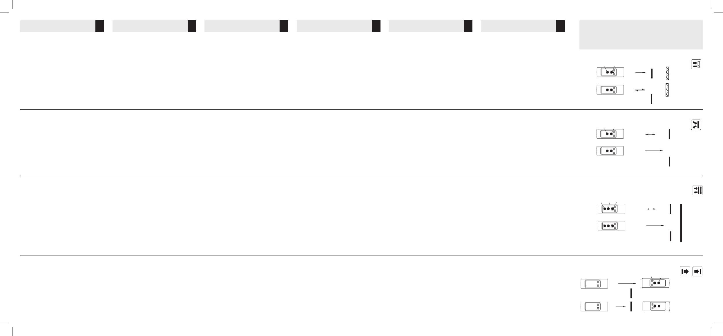
Retro-reflective and polarised Retro-reflective
sensor:
Mount the reflector and the sensor in the required
positions.
Turn the distance potentiometer clockwise to maxi-
mum. Adjust the sensor horizontally and vertically until
the yellow and the green LEDs go ON to ensure that
the beam hits the reflector.
Turn the distance potentiometer counter clockwise
until both LEDs go OFF.
For correct adjustment turn the distance potentiom-
eter clockwise until both LEDs are steadily ON again.
Diffuse-reflective:
Mount the sensor in the required position pointing
at the target.
Turn the distance potentiometer counter clockwise
to minimum.
Turn the distance potentiometer clockwise until the
yellow LED and green LEDs go ON.
Diffuse-reflective with background suppression:
Mount the sensor at the required distance from the
background.
Turn the “Tune” potmeter counter clockwise to mini-
mum. Turn the “Dist” potmeter clockwise from mini-
mum until the yellow LED goes on. Then turn counter
clockwise until the yellow LED turns off. Turn the
“Tune” potmeter clockwise until the yellow LED goes
on and then again counter clockwise until the yellow
LED turns off. The background is now suppressed.
The “Tune” adjustment potentiometer is facilitating
adjustment when target & background are close
together.
Through-beam sensor:
Mount the emitter and the receiver in the required
positions.
Turn the distance potentiometer on the receiver clock-
wise to maximum.
Move the receiver (and the emitter, if necessary) hor-
izontally and vertically until the yellow and the green
LEDs go ON and fix the sensors.
Turn the distance potentiometer counter-clockwise
until both LEDs go OFF.
For correct adjustment turn the distance potentiome-
ter clockwise until both LEDs are steadily ON.
Reflexions-Lichtschranke (mit Polarisationsfilter):
Den Reflektor und die Lichtschranke in der gewün-
schten Position montieren.
Das “Distance”-Potentio meter in die Maximalposition
drehen.
Die Lichtschranke vertikal und horizontal bewegen, bis
die gelbe und die grüne LED´s aufleuchten. Damit wird
sichergestellt, dass der Lichtstrahl den Reflektor trifft.
Das “Distance”-Potentiometer entge gen dem
Uhrzeigersinn drehen, bis beide LED´s erlöschen.
Zur korrekten Einstellung muss das “Distance”-
Potentiometer im Uhrzeigersinn gedreht werden, bis
beide LED´s konstant aufleuchten.
Reflexions-Lichttaster
Den Lichttaster in der gewünschten Position mon-
tieren.
Das “Distance”-Potentio meter in die Minimalposition
drehen.
Das “Distance”-Potentiometer im Uhrzeigersinn dre-
hen, bis die gelbe und die grüne LED´s aufleuchtet.
Reflexions-Lichtschalter mit
Hintergrundausblendung
Den Sensor in dem gewünschten Abstand von dem
Hintergrund montieren.
Das ”TUNE” Potentiometer entgegen dem
Uhrzeigersinn auf Minimum drehen. Das ”DIST”
Abstandspotentiometer im Uhrzeigersinn von
Minimum hinweg drehen, bis die gelbe LED leuchtet.
Dann entgegen dem Uhrzeigersinn drehen, bis die
gelbe LED erlischt. Das ”TUNE” Abstandspotentio-
meter im Uhrzeigersinn drehen, bis die gelbe
LED leuchtet, und dann wieder entgegen dem
Uhrzeigersinn drehen, bis die gelbe LED erlischt. Der
Hintergrund kann jetzt detektiert werden.
Das Tune Abstandspotentiometer erleichtert die
Einstellung, wenn der Hintergrund und das Objekt nah
beieinander sind.
Einweg-Lichtschranke:
Den Sender und den Empfänger in den gewünschten
Positionen montieren.
Das “Distance”-Potentio meter des Empfängers in die
Maxi malposition drehen.
Die Lichtschranken vertikal und horizontal bewegen,
bis die gelbe und die grüne LED´s aufleuchten. Damit
sind die Licht schranken korrekt installiert.
Das “Distance”-Potentiometer ge gen dem
Uhrzeigersinn drehen, bis beide LED´s erlöschen.
Zur korrekten Einstellung muss das “Distance”-
Potentiometer im Uhrzeigersinn gedreht werden, bis
beide LED´s kontinuierlich aufleuchtet.
Cellule réflexe et réflexe polarisée
Installer le réflecteur et le capteur aux positions
requises.
Régler le potentiomètre de distance au maximum en
le tournant dans le sens horaire. Ajuster le capteur
horizontalement et verticalement jusqu’à ce que les
LED jaune et verte s’allument afin de s’assurer que le
faisceau lumineux vienne frapper le réflecteur.
Régler le potentiomètre de distance au minimum en le
tournant dans le sens anti horaire jusqu’à ce que les
deux LED s’éteignent, puis pour obtenir un réglage
correct, tourner le potentiomètre de distance dans
le sens horaire jusqu’à ce que les deux LED restent
allumées en fixe.
Cellule à réflexion directe:
Installer le capteur dans la position en le faisant pointer
sur la cible.
Régler le potentiomètre de distance au minimum en le
tournant dans le sens horaire.
Tourner le potentiomètre de distance dans le sens
anti horaire jusqu’à ce que les LED jaune et verte
s’allument.
Réflexion directe avec suppression d’arrière plan
Installer le détecteur dans la position derrière par
rapport à l’arrière plan.
Tourner le potentiomètre « Tune » dans le sens des
aiguilles d’une montre jusqu’au minimum.
Tourner le potentiomètre « Dist » du minimum vers le
maximum jusqu’à l’allumage de la Led jaune.
Tourner le potentiomètre « Tune » jusqu’à l’allumage
de la Led jaune puis jusqu’à l’extinction.
L’arrière n’est désormais plus détecté.
Le potentiometre “Tune” permet un ajustement précis
quand l’objet à détecter est trés proche de l’arrière
plan.
Cellule barrage:
Installer l’émetteur et le récepteur aux positions
requises.
Sur le récepteur, amener le potentiomètre de distance
au maximum en le tournant dans le sens horaire.
Décaler le récepteur (et au besoin l’émetteur,) dans
les plans horizontaux et verticaux jusqu’à ce que les
LED jaune et verte s’allument, puis immobiliser les
capteurs.
Tourner le potentiomètre de distance dans le sens
anti horaire jusqu’à ce que les deux LED s’éteignent,
puis pour obtenir un réglage correct, tourner le
potentiomètre de distance dans le sens horaire
jusqu’à ce que les deux LED restent allumées en fixe.
Fotocélulas de reflexión sobre espejo y fotocélu-
las de reflexión sobre espejo polarizadas:
Monte el espejo y la fotocélula en las posiciones
requeridas.
Gire el potenciómetro de distancia en sentido horario
hasta llegar al máximo. Ajuste la fotocélula horizontal
y verticalmente hasta que se enciendan los LED
amarillo y verde para asegurar que el rayo apunte
hacia el espejo.
Gire el potenciómetro de distancia en sentido anti-
horario hasta que se apaguen los dos LED.
Para obtener el ajuste correcto, gire el potenciómetro
de distancia en sentido horario hasta que los dos LED
permanezcan constantemente encendidos.
Reflexión directa:
Monte la fotocélula en la posición requerida apuntan-
do hacia el objeto.
Gire el potenciómetro de distancia en sentido anti-
horario hasta llegar al mínimo.
Gire el potenciómetro de distancia en sentido horario
hasta que se enciendan el LED amarillo y los LED
verdes.
Reflexión directa con supresión de fondo:
Instale el sensor en la posición correcta de trabajo.
Gire el potenciómetro “Tune” en sentido antihorario
hasta el mínimo. Gire el potenciómetro “Dist” en sen-
tido horario desde el mínimo hasta que el LED amarillo
se ilumine. Después gire en sentido antihorario hasta
que el LED amarillo se apague. Gire el potenciómetro
“Tune” en sentido horario hasta que el LED amarillo
se ilumine y entonces gire en sentido antihorario
hasta que el LED amarillo se apague. El fondo está
ahora ignorado.
El potenciómetro de ajuste “Tune” facilita el ajuste
cuando el objeto y el fondo están próximos entre si.
Fotocélula de barrera:
Monte el emisor y el receptor en las posiciones
requeridas.
Gire el potenciómetro de distancia del receptor en
sentido horario hasta llegar al máximo.
Mueva el receptor (y, de ser necesario, el emisor) hor-
izontal y verticalmente hasta que se encienda el LED
amarillo y los dos LED verdes y luego fije las fotocélulas.
Gire el potenciómetro de distancia en sentido anti-
horario hasta que se apaguen los LED.
Para obtener el ajuste correcto, gire el potenciómetro
de distancia en sentido horario hasta que los LED
permanezcan constantemente encendidos.
Sensore a riflessione e sensore a riflessione
polarizzata:
Montare il catarifrangente ed il sensore nella posizione
desiderata.
Ruotare il potenziometro di regolazione della distanza
in senso orario sul massimo. Per assicurarsi che il
raggio luminoso raggiunga il catarifrangente, regolare
il sensore orizzontalmente e verticalmente finché i LED
giallo e verde non risultano entrambi accesi.
Ruotare il potenziometro di distanza in senso antio-
rario finché entrambi i LED non si spengono.
Per una regolazione corretta, girare il potenziometro
di distanza in senso orario finché entrambi i LED non
sono di nuovo costantemente accesi.
Sensori a riflessione diretta:
Montare il sensore nella posizione desiderata, puntato
verso l’oggetto di riferimento.
Ruotare il potenziometro di regolazione della distanza
in senso antiorario sul minimo.
Ruotare il potenziometro di distanza in senso orario
finché i LED giallo e verde non si accendono.
Riflessione diretta con soppressione di sfondo:
Montare il sensore nella posizione di lavoro. Girare
il potenziometro “tune” in senso antiorario al mini-
mo. Girare il potenziometro “Dist” in senso orario al
minimo finche il LED giallo non si accende. Girare in
senso antiorario fin che il LED giallo si spegne. Girare
il potenziometro “tune” in senso orario finche LED
giallo non si accende e subito dopo in senso antiorario
finche il LED giallo si spegne. Ora la regolazione della
soppressione è terminata.
Il potenziometro “tune” facilita’ la programmazione
nel caso in cui la distanza tra l’oggetto da rilevare e
lo sfondo e’ ridotta
Sensore a barriera:
Montare l’emettitore ed il ricevitore nella posizione
desiderata.
Ruotare il potenziometro di regolazione della distanza
del ricevitore in senso orario sul massimo.
Muovere orizzontalmente e verticalmente il ricevitore
(e l’emettitore, se necessario) finché i LED giallo e
verde non si accendono. Fissare i sensori.
Ruotare il potenziometro di distanza in senso antio-
rario finché entrambi i LED non si spengono.
Per una regolazione corretta, girare il potenziometro
di distanza in senso orario finché entrambi i LED non
rimangono costantemente accesi.
Retro-reflektiv og polariseret, retro-reflektiv
fotoaftaster:
Monter refleksbrikken og fotoaftasteren i de ønskede
positioner.
Drej afstandspotentiometeret med uret til maximum.
Juster aftasteren horisontalt og vertikalt indtil den
gule og den grønne lysdiode lyser; således sikres, at
lysstrålen rammer refleksbrikken.
Afstandspotentiometeret drejes mod minimum indtil
begge lysdioder slukker.
Derefter drejes mod maximum indtil begge lysdioder
lyser konstant.
Objektaftaster:
Placer aftasteren og objektet i de ønskede positioner.
Drej afstandspotentiometeret mod uret til minimum.
Drej afstandspotentiometeret med uret (mod maxi-
mum) indtil den gule og den grønne lysdiode lyser.
Objektaftaster med baggrundsudblænding:
Placer aftasteren i den ønskede afstand fra bag-
grunden.
Drej ”TUNE” afstandspotentiometeret mod uret til
minimum. Drej ”DIST” afstandspotentiometeret med
uret fra minimum indtil den gule lysdiode lyser.
Derefter drejes mod uret indtil den gule lysdiode
slukker. Drej ”TUNE” afstandspotentiometeret med
uret indtil den gule lysdiode lyser for derefter at dreje
mod uret indtil den gule lysdiode slukker. Baggrunden
er nu detekteret.
“Tune” justerings potentiometeret gør justeringen
lettere når emne og baggrund er tæt på hinanden.
Fotoaftaster med separat sender og modtager:
Monter senderen og modtageren i de ønskede posi-
tioner.
Drej afstandspotentiometeret på modtageren til max-
imum.
Bevæg modtageren (og evt. senderen) horisontalt og
vertikalt indtil den gule og den grønne lysdiode lyser.
Fastgør modtager og sender.
Afstandspotentiometeret drejes mod minimum (mod
uret) indtil begge lysdioder slukker.
Drej afstandspotentiometeret mod maximum indtil
begge lysdioder lyser konstant.
Optical alignment and
sensitivity adjustment
Einstellung der optischen
Achse und der Empfindlichkeit
Réglage de l’alignement
optique et de la sensibilité
Alineación óptica y ajuste
de sensibilidad
Allineamento ottico e
regolazione della sensibilità
Optisk indstilling og
følsomhedsjustering
Detection - Make switching (NO)
Erfassung – Schließkontakt (NO)
Détection – Commutation travail (NO)
Detección – Detección con luz (NA)
Rilevamento- Attivazione per impulso di luce (NA)
Aftastning – sluttefunktion (normalt åben – NO)
GB D F E I DK
DIST
NPN/PNP TUNE
ON
OFF
Target/object
Background

