SICK RT Photoelectric proximity sensor Bedienungsanleitung
- Typ
- Bedienungsanleitung

B4
B3
ENGLISH
Photoelectric proximity sensor
Operating instructions
Safety notes
> Not a safety component in accordance with EU Machinery Directive.
> Read the operating instructions before commissioning.
> Connection, mounting, and setting is only to be performed
by trained specialists.
> Whe
n commissioning, protect the device from moisture and
contamination.
Correct use
The R sensor is a photoelectric sensor that utilizes background suppres-
sion (BGS) technology and has a unique optical conguration that allows
product to be detected overhead when the sensor is mounted between
conveyor rollers.
Starting operation
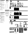
1 Mounting and electrical installation:
Mounting installation:
Mount the
R-Sensor
such that the top is positioned in the gap between
the rollers but below the conveying surface. Refer to drawing 1 and
make sure that the sensing distance, direction of product ow, and
the minimum distance to the sensor are within sensor specications.
Mounting brackets must be ordered separately (refer to www.sick.com).
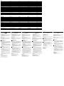
Electrical installation:
A Class 2 power source is required. Power may be supplied per pin
out shown in graphic B. Please refer to your sensors Part Code to
select the correct pin out diagram. The green indicating LED will
illuminate on the sensor when power is correctly applied.
2 Adjusting the sensor
The R-Sensor has an 9 turn potentiometer, please handle carefully
when reaching the end positions.
If the amber LED is illuminated, turn the potentiometer counterclock-
wise until it is o as shown in Figure 2.
Position the darkest expected target at the maximum distance away
from the sensor face.
Turn the potentiometer clockwise as shown in Figure 2 until the amber
LED illuminates. If it does not illuminate, check the application again
by referring to Figure 3.
Remove the target. The amber LED should turn o. If it does not, the
background is too close to the target. Check the application again by
referring to Figure 3
Visit “http://www.sick.com/zonecontrol” for more information on
ZoneControl products.
Maintenance
SICK light barriers are maintenance-free.
We recommend doing the following regularly:
- clean the external lens surfaces
- check the screw connections and plug-in connections.
No modications may be made to devices.
DEUTSCH
Reexions-Lichttaster
Betriebsanleitung
Sicherheitshinweise
> Kein Sicherheitsbauteil gemäß EU-Maschinenrichtlinie.
> Vor der Inbetriebnahme die Betriebsanleitung lesen.
> Anschluss, Montage und Einstellung nur durch Fachpersonal.
> Gerät bei Inbetriebnahme vor Feuchte und Verunreinigung schützen.
Bestimmungsgemäße Verwendung
Der R-Sensor ist eine Lichtschranke mit Hintergrundausblendung (HGA) und
einer speziellen optischen Parametrierung, welche die Overhead-Detektion
von Produkten ermöglicht, wenn der Sensor zwischen Rollenförderern
angebracht ist.
Inbetriebnahme
1 Montage und elektrische Installation:
Montage:
Montieren Sie den R-Sensor so, dass sich die Oberseite in dem
Zwischenraum zwischen den Rollen, jedoch unter der Förderäche
bendet. Beachten Sie dabei Zeichnung 1 und stellen Sie sicher,
dass die Sensorreichweite, die Richtung des Produktusses und der
Mindestabstand zum Sensor den Sensorspezikationen entsprechen.
Die Haltewinkel sind nicht im Lieferumfang enthalten und müssen
separat bestellt werden (siehe www.sick.com).
Elektrische Installation:
Es wird eine Stromquelle der Klasse 2 benötigt. Die Stromversorgung
kann, wie in Grak B dargestellt, per Pin erfolgen. Wählen Sie das
richtige Pin-Out-Diagramm anhand der Teilenummer des Sensors.
Die grüne LED an jedem Sensor leuchtet auf, wenn die Stromversor-
gung korrekt angeschlossen ist.
2 Einstellung des Sensors
Der IR-Sensor verfügt über ein Potentiometer mit 9 Umdrehungen.
Bitte gehen Sie beim Erreichen der Endpositionen vorsichtig damit um.
Wenn die gelbe LED leuchtet, drehen Sie das Potentiometer, wie in
Abbildung 2 dargestellt, im Uhrzeigersinn, bis diese aus ist.
Positionieren Sie das dunkelste Target im maximalen Abstand zur
Sensoräche.
Drehen Sie das Potentiometer, wie in Abbildung 2 dargestellt,
im Uhrzeigersinn, bis die gelbe LED aueuchtet. Wenn diese nicht
aueuchtet, überprüfen Sie die Applikation noch einmal anhand
von Abbildung 3.
Entfernen Sie das Target. Die gelbe LED sollte nun ausgehen.
Wenn dies nicht der Fall ist, dann wird die Applikation durch den Hin-
tergrund gestört. Überprüfen Sie die Applikation noch einmal anhand
von Abbildung 3.
Unter „http://www.sick.com/zonecontrol“ nden Sie eine Simulation
der Logik und weitere Informationen zu den ZoneControl-Produkten.
Wartung
SICK-Lichtschranken sind wartungsfrei.
Wir empfehlen, in regelmäßigen Abständen
– die optischen Grenzächen zu reinigen,
– Verschraubungen und Steckverbindungen zu überprüfen.
Veränderungen an Geräten dürfen nicht vorgenommen werden.
More representatives and agencies at www.sick.com ∙ Subject to change
without notice ∙ The specied product features and technical data do not
represent any guarantee.
Weitere Niederlassungen nden Sie unter www.sick.com ∙ Irrtümer
und Änderungen vorbehalten ∙ Angegebene Produkteigenschaften und
technische Daten stellen keine Garantieerklärung dar.
Plus de représentations et d’agences à l’adresse www.sick.com ∙ Sujet à
modication sans préavis ∙ Les caractéristiques de produit et techniques
indiquées ne constituent pas de déclaration de garantie.
Para mais representantes e agências, consulte www.sick.com ∙ Alterações
poderão ser feitas sem prévio aviso ∙ As características do produto e os
dados técnicos apresentados não constituem declaração de garantia.
Altri rappresentanti ed agenzie si trovano su www.sick.com ∙ Contenuti
soggetti a modiche senza preavviso ∙ Le caratteristiche del prodotto e i dati
tecnici non rappresentano una dichiarazione di garanzia.
Más representantes y agencias en www.sick.com ∙ Sujeto a cambio sin
previo aviso ∙ Las características y los datos técnicos especicados no
constituyen ninguna declaración de garantía.
欲了解更多代表机构和代理商信息,请登录 www.sick.com ∙
如有更改 , 不另行通知 ∙ 对所给出的产品特性和技术参数
的正确性不予保证。
その他の営業所は www.sick.com よりご覧ください ∙ 予告なし
に変更されることがあります ∙ 記載されている製品機能およ
び技術データは保証を明示するものではありません。
RT
Australia
Phone +61 3 9457 0600
Belgium/Luxembourg
Phone +32 (0)2 466 55 66
Brasil
Phone +55 11 3215-4900
Canada
Phone +1 905 771 14 44
Ceská Republika
Phone +420 2 57 91 18 50
China
Phone +86 4000 121 000
+852-2153 6300
Danmark
Phone +45 45 82 64 00
Deutschland
Phone +49 211 5301-301
España
Phone +34 93 480 31 00
France
Phone +33 1 64 62 35 00
Great Britain
Phone +44 (0)1727 831121
India
Phone +91–22–4033 8333
Israel
Phone +972-4-6801000
Italia
Phone +39 02 27 43 41
Japan
Phone +81 (0)3 3358 1341
Magyarország
Phone +36 1 371 2680
Nederlands
Phone +31 (0)30 229 25 44
Österreich
Phone +43 (0)22 36 62 28 8-0
Norge
Phone +47 67 81 50 00
Polska
Phone +48 22 837 40 50
România
Phone +40 356 171 120
Russia
Phone +7-495-775-05-30
Schweiz
Phone +41 41 619 29 39
Singapore
Phone +65 6744 3732
Slovenija
Phone +386 (0)1-47 69 990
South Africa
Phone +27 11 472 3733
South Korea
Phone +82 2 786 6321/4
Suomi
Phone +358-9-25 15 800
Sverige
Phone +46 10 110 10 00
Taiwan
Phone +886-2-2375-6288
Türkiye
Phone +90 (216) 528 50 00
United Arab Emirates
Phone +971 (0) 4 8865 878
USA/México
Phone +1(952) 941-6780
BZ int40
Please find detailed addresses and additional representatives and agencies in
all major industrial nations at www.sick.com
--------------------------------------------------------------------- 8016162 0713 CV -------------------------------------------------------------------
SICK AG, Erwin-Sick-Strasse 1, D-79183 Waldkirch
A RX-xxxx1 all others / alle anderen
B1
+ (L+)
See Y
See Y
brn
blk
wht
0 VDC
blu
B5 B6
B7
B8
1-L+ 2-Q1 3-0V
0 VDC Output
+VDC
PIN
6
= NC
PIN
5
= 0 VDC
PIN
4
= See Y
PIN
3
= See Y
PIN
2
= +24 VDC
PIN
1
= NC
Front of Connector
not connected
+ (L+)
See Y
1
2
3
See Y
4
0 VDC
5
not connected
6
PIN1 = + 24 VDCInsertion Side
PIN4 = Alarm
PIN3 = 0 VDC
PIN2 = QPNP
PIN1, brown, + 24 VDC
PIN2, white, QNPN
PIN3, blue, 0 VDC
QPNP
PIN1, + 24 VDC
PIN2, 0 VDC
PIN3, QNPN
+ 24 VD
C
Q
LO
0 VDC
Q
LO
1
2
4
3
+ (L+)
Q
LO
Q
LO
brn
blk
wht
1
4
2
0 VDC
blu
3
Flying leads Rx-xx1xx
M8
M8 / M12 Rx-xx2xx
Rx-xx3xx
Rx-xx4xx
RT-P4000S02
RT-B1624S04
RT-N1000S05, RT-N1000S06, RT-N1000S07
RT-P1221S10
1
A (max. 900 mm) (35.43 inch)
7°
B
A (max. 900 mm)
(35.43 inch)
B
2
1) 1)
1) Potentiometer will be turned either counterclockwise
or clockwise depending on the instructions
2) The amber LED illuminates when a target is detected
within the sensing range. When flashing a target is being
detected, but only with a marginal signal.
3) The green LED illuminates when power is on
4) For versions with options referenced in features 4,
the LED 2) has a built-in potentiometer to set them.
- Timer versions: Left stop (CCW) = min. delay
- LO / DO Switching versions: Left stop (CCW) = LO
3) 3)
2)
2)
3
1000
(39.37)
800
(31.5)
600
(23.62)
400
(15.75)
200
(7.87)
0
0
4
8
12
16
20
24
28
%
Distance in mm (inch)
5 % / 90 %
90 % / 90 %
7°
Sender
8.5 (0.33)
4°
4.0
(0.16)
40.0 (1.57)
48.0 (1.89)
52.0 (2.05) 43.2 (1.7)
4.0
(0.16)
Ø 4.5
(0.18)
48.9 (1.93)
40.9 (1.61)
20.6 (0.81)
18.0
(0.71)
99.2 (3.91)
88.3
(3.48)
42.0 (1.65)
23.0 (0.91)
7°
Sender
8.5 (0.33)
4°
4.0
(0.16)
40.0 (1.57)
48.0 (1.89)
52.0 (2.05) 43.2 (1.7)
4.0
(0.16)
Ø 4.5
(0.18)
48.9 (1.93)
40.9 (1.61)
20.6 (0.81)
18.0
(0.71)
99.2 (3.91)
88.3 (3.48)
42.0 (1.65)
Rx-PY11x
Rx-NY11x
Rx-MY11x
P = PNP
N = NPN
M = FET Output
Rx-BY11x B = PNP / NPN
Y blk wht blk wht
1 Q
LO
not connected QP
LO
QN
LO
2 Q
DO
not connected QP
DO
QN
DO
3 Q
LO
Q
DO
4 Q
LO
Alarm
5 Q
LO
Health
6 Q
DO
Alarm
7 Q
DO
Health
+ 24 VD
C
See Y
0 VDC
See Y
1
2
4
3
See Y
See Y
+ 24 VDC
0 VD
C
4
2
3
1
M12
Rx-(P / N)Y22x
Rx-(P / N)Y32x
Rx-(P / N)Y42x
P = PNP
N = NPN
Rx-(P / N)Y23x
Rx-(P / N)Y33x
Rx-(P / N)Y43x
P = PNP
N = NPN
Rx-BY22x
Rx-BY32x
Rx-BY42x
B = PNP / NPN
Y PIN4 PIN2 PIN4 PIN2 PIN4 PIN2
1 Q
LO
not connected not connected Q
LO
QP
LO
QN
LO
2 Q
DO
not connected not connected Q
DO
QP
DO
QN
DO
3 Q
LO
Q
DO
Q
DO
Q
LO
- -
4 Q
LO
Alarm Alarm Q
LO
- -
5 Q
LO
Health Health Q
LO
- -
6 Q
DO
Alarm Alarm Q
DO
- -
7 Q
DO
Health Health Q
DO
- -
Rx-xY52x Rx-xY53x
Y PIN3 PIN4 PIN3 PIN4
1 Q
LO
not connected not connected Q
LO
2 Q
DO
not connected not connected Q
DO
3 Q
LO
Q
DO
Q
DO
Q
LO
4 Q
LO
Alarm Alarm Q
LO
5 Q
LO
Health Health Q
LO
6 Q
DO
Alarm Alarm Q
DO
7 Q
DO
Health Health Q
DO
RJ11 Rx-xx5xx
Rx-xY62x
Y PIN2
1 Q
LO
2 Q
DO
WAGO Rx-xx6xx
4
Features
RT-xxxxxx - -
RTN-xxxxxx ON Delay -
Adjustable
0–5 seconds
RTF-xxxxxx OFF Delay -
Adjustable
0–5 seconds
RTT-xxxxxx Special Timing
RTQ-xxxxxx Switch Selectable
Light / Dark
Operate - LO / DO
(applies to all
relavent outputs)
Factory default;
Q
1
= LO
B2
Seite wird geladen ...
-
 1
1
-
 2
2


SICK RT Photoelectric proximity sensor Bedienungsanleitung
- Typ
- Bedienungsanleitung
in anderen Sprachen
- English: SICK RT Photoelectric proximity sensor Operating instructions
- français: SICK RT Photoelectric proximity sensor Mode d'emploi
- español: SICK RT Photoelectric proximity sensor Instrucciones de operación
- italiano: SICK RT Photoelectric proximity sensor Istruzioni per l'uso
- português: SICK RT Photoelectric proximity sensor Instruções de operação
- 日本語: SICK RT Photoelectric proximity sensor 取扱説明書
Verwandte Artikel
-
SICK WL(F)18-3 Compact photoelectric sensors Bedienungsanleitung
-
-
-
-
-
-
-
-
-