Pepperl+Fuchs UDC-18GM50-255S-3E0 Bedienungsanleitung
- Typ
- Bedienungsanleitung

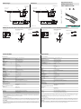
Abmessungen
Elektrischer Anschluss/Kurven/
Zusätzliche Informationen
Electrical Connection / Curves / Additional Information
Dimensions
Technische Daten
Technical data
UDC-18GM50-255S-3E0
Auswerteeinheit mit
Empfangseinheit
Sendeeinheit
Litzen 70 mm mit
Aderendhülsen
l = 0.5 m
50
30
53
M18 x 1
4
24
LEDs
ø 15
70
M18 x 1
40
24
500
l = 2 m
Evaluation unit with
receiver unit
Emitter unit
wires 70 mm with
wire end ferrules
l = 0.5 m
50
30
53
M18 x 1
4
24
LEDs
ø 15
70
M18 x 1
40
24
500
l = 2 m
(BN)
(PK)
(WH)
(BK)
(GY)
+UB
-UB
(BU)
U
Normsymbol/Anschluss:
Doppelbogen-Kontrolle
Ausgang Doppelbogen
Ausgang Luft
Funktionseingang
Ausgang Einzelbogen
Montage/Ausrichtung:
Empfohlende Abstände
a
d
b
a = 15 ... 25 mm
b ≥ 10 mm
d = 60 ... 80 mm
β = 20° ... 40°
β
α
s
α < +/- 1˚
s
< +/- 1 mm
Winkelversatz
Sensorversatz
a
s
a < +/- 1°
s < +/- 1 mm
Angular misalignment
Sensor offset
Mounting/Adjustment
Recommended distances
a
d
b
a = 15 ... 25 mm
b ≥ 10 mm
d = 60 ... 80 mm
β = 20° ... 40°
β
(BN)
(PK)
(WH)
(BK)
(GY)
+UB
-UB
(BU)
U
Standard symbol/Connection:
Double sheet control
Output double sheet
Output air
Output single sheet
Function input
Partnummer / Part. No.:
Datum / Date:
206053
07/02/2014 DIN A3 -> DIN
45-2788E
Doc. No.:
Beschreibung der Sensorfunktionen
Ultraschall Doppelmaterial-Sensoren werden überall dort eingesetzt, wo eine automatische Unterscheidung von doppelten und ein-
zelnen flächigen Materialien notwendig ist, um Maschinen zu schützen oder Ausschuss zu vermeiden. Der Doppelmaterial-Sensor
basiert auf dem Ultraschall-Einweg-Prinzip. Es lassen sich detektieren:
- kein Material, d.h. Luft,
-Einzel-Material
- Doppel- bzw. mehrlagiges Material
Die Auswertung der Signale erfolgt mit einem Mikroprozessorsystem. Als Folge derAuswertung werden die entsprechenden Schalt-
ausgänge gesetzt. Sich ändernde Umgebungsbedingungen wie Temperatur oder Feuchtigkeit werden automatisch kompensiert. Die
Auswerteelektronik ist in einer Auswerteeinheit zusammen mit einem Sensorkopf in einem kompakten M18 Metallgehäuse eingebaut.
Anschaltung
Der Sensor verfügt über 6 Anschlüsse. Die Funktion der Anschlüsse sind in der Nachfolgenden Tabelle aufgeführt. Der Funktionsein-
gang (PK) dient zur Parametrierung des Sensors. (siehe Ausgangsimpulsverlängerung, Ausrichthilfe und Programmauswahl). Im lau-
fenden Betrieb muss der Funktionseingang immer fest mit +UB oder -UB verbunden sein, um eventuelle Störungen oder
Fehlfunktionen zu vermeiden.
Allgemeine Daten
Erfassungsbereich 40 ... 100 mm , optimaler Abstand: 75 mm
Wandlerfrequenz 255 kHz
Anzeigen/Bedienelemente
LED grün Anzeige: Einzelmaterial detektiert
LED gelb Anzeige: kein Material detektiert (Luft)
LED rot Anzeige: Doppelmaterial detektiert
Elektrische Daten
Betriebsspannung UB18 ... 30 V DC , Welligkeit 10 %SS
Leerlaufstrom I0< 65 mA
Bereitschaftsverzug tv< 500 ms
Eingang
Eingangstyp Funktionseingang
0-Pegel: -UB ... -UB + 1V
1-Pegel: +UB - 1 V ... +UB
Impulsdauer 100 ms
Impedanz 4 k
Ausgang
Ausgangstyp 3 Schaltausgänge npn, Schließer
Bemessungsbetriebsstrom Ie3 x 100 mA , kurzschluss-/überlastfest
Spannungsfall Ud 3 V
Einschaltverzug ton ca. 35 ms
Ausschaltverzug toff ca. 35 ms
Impulsverlängerung min. 120 ms parametrierbar
Umgebungsbedingungen
Umgebungstemperatur 0 ... 60 °C (32 ... 140 °F)
Lagertemperatur -40 ... 85 °C (-40 ... 185 °F)
Mechanische Daten
Anschlussart Kabel PVC , 2 m
Aderquerschnitt 0,14 mm2
Schutzart IP67
Material
Gehäuse Messing, vernickelt, Kunststoffteile PBT
Wandler Epoxidharz/Glashohlkugelgemisch; Schaum Polyurethan
Masse 150 g
Werkseinstellungen
Programm 1
Allgemeine Informationen
Ergänzende Informationen Schalterstellung des externen Programmieradapters:
"output load": pull-up
"output logic": inv
Normen- und Richtlinienkonformität
Normenkonformität
Normen EN 60947-5-2:2007
IEC 60947-5-2:2007
Zulassungen und Zertifikate
UL-Zulassung cULus Listed, General Purpose, Class 2 Power Source
CSA-Zulassung cCSAus Listed, General Purpose, Class 2 Power Source
CCC-Zulassung Produkte, deren max. Betriebsspannung 36 V ist, sind nicht zulassungspflichtig und daher nicht mit einer CCC-
Kennzeichnung versehen.
Description of the sensor functions
Ultrasonic double material sensors are used in any situation where it is necessary to make an automatic distinction between a single
sheet of material and a double sheet of material in order to provide protection for a machine and/or to avoid wastage. The double
material sensor is based on the ultrasonic single-pass principle. The following situations can be detected:
- No material, i.e. air
- Single layer of material
- 2 or more layers of material
The evaluation of the signals is carried out with a microprocessor system. As a consequence of the evaluation the corresponding
switch outputs are set. Changing ambient conditions, such as temperature and humidity, are automatically compensated. The evalu-
ation electronics system is built into an evaluation unit, together with a sensor head, and contained in a compact M18 metal housing.
Interface
The sensor has 6 connections. The function of the connections is shown in the following table. The function input (PK) is used to con-
figure the sensor parameters. (see Output pulse expansion, alignment aids and program select). During operation, the function input
must always be permanently connected to +UB or -UB to prevent possible faults or malfunctions.
General specifications
Sensing range 40 ... 100 mm optimal distance 75 mm
Transducer frequency 255 kHz
Indicators/operating means
LED green Indicator: single material detected
LED yellow Indicator: no material detected (air)
LED red Indicator: double material detected
Electrical specifications
Operating voltage UB18 ... 30 V DC , ripple 10 %SS
No-load supply current I0< 65 mA
Time delay before availability tv< 500 ms
Input
Input type Function input
0-level: -UB ... -UB + 1V
1-level: +UB - 1 V ... +UB
Pulse length 100 ms
Impedance 4 k
Output
Output type 3 switch outputs NPN, NO
Rated operating current Ie3 x 100 mA , short-circuit/overload protected
Voltage drop Ud 3 V
Switch-on delay ton approx. 35 ms
Switch-off delay toff approx. 35 ms
Pulse extension min. 120 ms programmable
Ambient conditions
Ambient temperature 0 ... 60 °C (32 ... 140 °F)
Storage temperature -40 ... 85 °C (-40 ... 185 °F)
Mechanical specifications
Connection type cable PVC , 2 m
Core cross-section 0.14 mm2
Degree of protection IP67
Material
Housing nickel plated brass; plastic components: PBT
Trans ducer epoxy resin/hollow glass sphere mixture; polyurethane foam
Mass 150 g
Factory settings
Program 1
General information
Supplementary information Switch settings of the external programming adapter:
"output load": pull-up
"output logic": inv
Compliance with standards and directives
Standard conformity
Standards EN 60947-5-2:2007
IEC 60947-5-2:2007
Approvals and certificates
UL approval cULus Listed, General Purpose, Class 2 Power Source
CSA approval cCSAus Listed, General Purpose, Class 2 Power Source
CCC approval CCC approval / marking not required for products rated 36 V
Doppelmaterial-Sensor
Double material sensor
Alle Abmessungen in mm All dimensions im mm

Adressen / Addresses / Adresses / Direcciónes / Indirizzi
Contact Pepperl+Fuchs GmbH · 68301 Mannheim · Germany · Tel. +49 621 776-4411 · Fax +49 621 776-27-4411 · E-mail: fa-i[email protected]uchs.com
Worldwide Headquarters: Pepperl+Fuchs GmbH · Mannheim · Germany · E-mail: [email protected]fuchs.com
USA Headquarters: Pepperl+Fuchs Inc. · Twinsburg · USA · E-mail: fa-info@us.pepperl-fuchs.com
Asia Pacific Headquarters: Pepperl+Fuchs Pte Ltd · Singapore · E-mail: fa-info@sg.pepperl-fuchs.com · Company Registration No. 199003130E
For more contact-adresses refer to the catalogue or internet: http://www.pepperl-fuchs.com
Normalbetrieb
Der Sensor arbeitet im Normalbetrieb, wenn der Funktionseingang (PK) bei Anlegen der Versorgungsspannung (Power-On) auf -UB
oder +UB gelegt ist, entsprechend Tabelle Ausgangsimpulsverlängerung (siehe unten).
Anzeigen:
LED gelb: Erkennung Luft
LED grün: Erkennung Einzelmaterial
LED rot: Erkennung Doppelmaterial
Schaltausgänge:
Nur im Normalbetrieb sind die Schaltausgänge aktiv!
Weiß: WH Ausgang Einzelmaterial
Schwarz: BK Ausgang Doppelmaterial
Grau:GYAusgang Luft
Ausgangsimpulsverlängerung
Durch Anschalten des Funktionseingangs (PK) an +UB kann eine Mindestimpulsbreite von 120 ms für alle Ausgangsimpulse der drei
Schaltausgänge gewählt werden.
Achtung:
Es kann dadurch zu einem Zustand kommen, bei dem mehr als nur ein Schaltausgang durchgeschaltet ist!
Programme
Der Sensor verfügt über 4 Programme für verschiedene Einsatzbereiche. Dies ermöglicht die Erfassung eines breiten Materialspek-
trums. Der Anwender kann das für seine Applikation geeignete Programm auswählen.
Die Standardeinstellung Programm 1 ist so gewählt, dass für die Mehrheit der Applikationen keine Änderung der Einstellung notwen-
dig ist.
Die angegebenen Verwendungszwecke der Programme 1 ... 4 stellen Orientierungswerte für den Anwender dar. Im konkreten Ein-
zelfall ist die Auswahl des geeigneten Programms für das jeweils verwendete Material empirisch zu ermitteln. Ausgangspunkt sollte
dabei das Standardprogramm 1 sein.
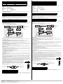
Einstellmöglichkeiten mit dem Funktionseingang
Im folgenden sind die Einstellmöglichkeiten mit dem Funktionseingang dargestellt.
Programmanzeige
Das voreingestellte Programm des Sensors kann angezeigt werden, indem man während des Normalbetriebs den Funktionseingang
(PK) spannungsfrei schaltet.
Die grüne LED zeigt die Programmnummer an (Anzahl der Blinkimpulse (1...4) = Programmnummer).
Die Ausgänge sind in dieser Zeit inaktiv.
Falls während des Betriebs der Funktionseingang (PK) durch einen Fehler (Kabelbruch, Lösen durch Vibrationen) spannungsfrei ge-
schaltet ist, so dient die Programmanzeige als Störmeldung. Ein Wechsel in den Programmiermodus ist nicht möglich.
Programmiermodus
Um in den Programmiermodus zu gelangen, muss beim Anlegen der Versorgungsspannung (Power-On) der
Funktionseingang (PK) spannungsfrei geschaltet sein. Der Sensor zeigt zunächst das eingestellte Programm durch Blinken der grü-
nen LED an (Anzahl der Blinkimpulse (1...4) = Programmnummer).
Durch kurzes Tasten des Funktionseingangs (PK) auf -Ub (>500ms) kann nun zyklisch zwischen der Amplitudenkontrolle und der
Programmwahl gewechselt werden.
Durch Abtrennen der Versorgungsspannung verlassen Sie den Programmiermodus mit der gewählten Programmeinstellung.
Die Schaltausgänge sind während der Parametrierung des Sensors nicht aktiv!
Amplitudenkontrolle
Bei der Montage kann die Amplitudenkontrolle zur Überprüfung auf ausreichende Ultraschallamplitude am Empfänger verwendet
werden.
Ist der Sender zum Empfänger nicht optimal ausgerichtet, so kommt nicht die volle Schallenergie am Empfänger an. Dies kann dazu
führen, dass Materialien nicht korrekt detektiert werden können.
Wenn der Sensor den Luftbereich erkennt (gelbe LED leuchtet), dann beginnt die UDC die Stärke des gemessenen Amplitudensig-
nals anzuzeigen:
- bei einem schwachen Signal blinkt die gelbe LED mit niedriger Frequenz
- mit steigender Signalstärke steigt die Blinkfrequenz
- bei ausreichender Signalstärke leuchtet die gelbe LED permanent.
Die Funktion Einzelbogen (grüne LED) und Doppelbogen (rote LED) ist hierbei weiterhin aktiv. Es kann somit die korrekte Funktion
des Doppelmaterial-Sensors überprüft werden.
Programmwahl
Im Modus Programmwahl wird durch kurzes Tasten des Funktionseingangs (PK) auf +Ub (>500ms) zyklisch das jeweils nächste Pro-
gramm gewählt (Anzahl Blinkimpulse der grünen LED = Programmnummer). Eine begonnene Blinksequenz wird nicht durch einen
Programmwechsel unterbrochen.
Hinweise:
Ein komplettes Gerät besteht aus einem Ultraschall-Sender und einem Auswertegerät mit Ultraschall-Empfänger. Die Sensorköpfe sind ab Werk
optimal aufeinander abgestimmt und dürfen daher nicht getrennt verwendet werden. Die Stecker-Trennstelle am Verbindungskabel Sender-
Empfänger dient lediglich der leichteren Montage.
Perforierte oder mit Löchern versehene Materialien sind aus physikalischen Gründen nicht immer zur Doppelmaterialerkennung geeignet.
Werden mehrere Doppelmaterial-Sensoren UDC in unmittelbarer Nähe zueinander eingesetzt, kann es zur gegenseitigen Beeinflussung und
damit zur Fehlfunktion der Geräte kommen. Gegenseitige Beeinflussung ist durch geeignete Gegenmaßnahmen bereits bei der Planung der An-
lagen zu vermeiden.
Es ist bei der Installation darauf zu achten, dass das Ultraschallsignal das zu erfassende Material nicht durch Mehrfachreflexionen umgehen kann.
Dies kann geschehen, wenn z. B. größere Flächen zur Schallreflexion quer zur Ausbreitungsrichtung des Schalls zur Verfügung stehen. Dies kann
durch ungeeignete Haltevorrichtungen oder durch großflächige Anlagenteile der Fall sein. Im Falle reflektierender Anlagenteile, müssen diese
entweder mit Schall absorbierendem Material beklebt werden oder ein anderer Montageort gewählt werden.
Eine einwandfreie Funktion des Sensors ist nur dann gewährleistet, wenn Sender und Empfänger ex-
akt zentrisch zueinander ausgerichtet sind.
Die Sensorköpfe und die Auswerteeinheit müssen ungeerdet eingebaut werden. Hierzu eignet sich
die Befestigung mit den mitgelieferten Kunststoff-Muttern. Diese sind einseitig mit einem Zentrierring
ausgestattet, der die Kontaktgabe zum Trägermaterial sicher verhindert. Die nebenstehende Skizze
zeigt die möglichen Orientierungen. Der Bohrungsdurchmesser im Trägermaterial muss 20 mm be-
tragen.
Parametrierung mit PACTware DTM
Der Anschluss des Doppelbogensensors erfolgt z.B. über den Klemmenadapter V15S-G-0,3M-PUR-WAGO.
Verbinden Sie den Sensor mit dem Klemmenadapter gemäß nachfolgender Tabelle.
Der Sensor ist mit einem Zeitschloss versehen. Falls kein Kommunikationsaufruf erfolgt, sperrt dies den Sensor 30 Sekunden nach dem Zuschalt-
en der Versorgungsspannung gegen Parametrieren. Starten Sie PACTware schon bevor Sie den Sensor einschalten damit der Kommunikation-
saufruf rechtzeitig erfolgen kann.
Farbe Anschaltung Bemerkung
BN +UB
WH Schaltausgang Einzelmaterial Impulsbreite entsprechend dem Ereignis
BK Schaltausgang Doppelmaterial Impulsbreite entsprechend dem Ereignis
GY Schaltausgang Luft Impulsbreite entsprechend dem Ereignis
PK -UB/+UBFunktionseingang zur Parametrierung/Impulsverlänge-
rung
BU -UB
Anschaltung (PK) Schaltverhalten (nach Power-On)
-UBKeine Ausgangsimpulsverlängerung der Schaltausgänge
+UBAusgangsimpulsverlängerung aller Schaltausgänge auf mindestens 120 ms
Programmnummer Anmerkungen*
1 Standardeinstellung. Deckt ein weites Materalspektrum ab
2 Dicke, schwere Materialien
3Dünne Materialien
4 Feinstmaterialien, Folien
Aderfarbe Klemmenadapter Aderfarbe Sensorkabel
braunbraun
blaublau
schwarz schwarz
graupink
+UB
-UB
-UB
-UB
+UB+UB
Power ONNormalbetriebUmschaltung
Impulsverlängerung
... und Funktionseingang
(PK) spannungsfrei
Funktionseingang
(PK) spannungsfrei
... und Funktionseingang (PK)
auf +UB oder -UB legen
keine Funktion wähle zyklisch
nächstes Programm
Programmier-
anzeige
Programmiermodus
Programmier-
anzeige
Amplitudenkontrolle
(gelbe LED)
Programmwahl
(grüne LED)
M12 Buchse
des UC-PROG1
Anschlusskabel des
Doppelbogensensors
V15S-G-0,3M-PUR-WAGO
Normal operation
The sensor operates in normal mode if the function input (PK) is set to -UB or +UB when the supply voltage is applied (power on) as spe-
cified in the output pulse expansion table (see below).
Display:
Yellow LED: Air detection
Green LED: Detection of single material
Red LED: Detection of double material
Switching outputs:
The switching outputs are only active in normal mode!
White: WH Single material output
Black: BK Double material output
Gray: GY Air output
Output pulse expansion
A minimum pulse width of 120 ms can be selected for all the output pulses of the three switching outputs by connecting the function input
(PK) to +UB.
Caution!
This can lead to a situation where more than one switch output is switched through!
Programs
The sensor has 4 programs for different application areas. This enables a wide range of materials to be detected. The user can select
the program most suited to the relevant application.
The default setting program 1 is selected so that the settings of the majority of applications do not need modifying.
The applications specified in Programs 1 ... 4 provide orientation values for the user. In a specific individual case the selection of the sui-
table program for the respective material in use has to be obtained empirically. In this procedure the starting point should be the standard
Program 1.
Adjustment options using the function input
The adjustment options are indicated in the following, together with the function input.
Program display
The preset sensor program can be displayed by disconnecting the function input (PK) from the power supply during normal operation.
The green LED indicates the program number (number of flashing pulses (1...4) = program number).
The outputs are inactive during this time.
If the function input (PK) is disconnected from the power during operation due to a fault (cable break, loosening due to vibration), the pro-
gram display also serves as a fault display. Changing to programming mode is not possible.
Programming mode
To activate the programming mode,
the function input (PK) must be disconnected from the power when the supply voltage is applied (power on). The flashing green LED linked
to the sensor indicates the preset program first (number of flashing pulses (1...4) = program number).
By briefly setting the function input (PK) to -Ub (>500ms), it is now possible to switch cyclically between the amplitude control and the
program selection.
By disconnecting the supply voltage, you exit the programming mode and the current selected program setting is applied.
The switching outputs are deactivated while the sensor is parameterized!
Amplitude control
During installation, the amplitude control can be used to check whether the ultrasonic amplitude at the receiver is sufficient.
If the transmitter is not aligned properly in relation to the receiver, maximum sound energy is not transmitted to the receiver, which may
result in the incorrect detection of materials.
When the sensor detects an area of air (yellow LED lights up), the UDC begins to display the strength of the measured amplitude signal:
- if the signal is weak, the yellow LED flashes at low frequency
- the flashing frequency increases in line with the signal strength
- the yellow LED lights up continuously when the signal strength is sufficient.
The single sheet function (green LED) and double sheet function (red LED) are now active. This can be used to check the correct function
of the double material sensor.
Program select
In program select mode, briefly setting the (PK) to +Ub (>500ms) selects the next program cyclically (number of flashing pulses from the
green LED = program number). A flashing sequence that has already started is not interrupted by a program change.
Note:
A complete device consists of one ultrasonic sensor and one evaluation unit with the ultrasonic receiver. The sensor heads are optimally matched to
each other in the ex-works condition and should therefore not be used separately. The connector disconnection point on the transmitter/receiver con-
nection cable is merely provided to simplify assembly.
Because of their physical condition, materials that are perforated or otherwise contain holes are not always suitable for double sheet material detection.
If a number of UDC double material sensors are installed close together there is the possibility of mutual interference, leading to the occurrence of faults.
Mutual interference can be avoided by suitable countermeasures implemented when planning the system.
On installation, care should be taken, that the ultrasonic signal cannot pass around the material to be detected due to multiple reflections. This can
happen if, for example, there are large surfaces capable of reflecting the sound at right angles to the direction of propagation of the sound. This can be
the case when unsuitable clamping devices are used, or may be due to plant components with large surfaces. In the case of reflecting plant compo-
nents, these must either be clad with sound-absorbing material, or an alternative mounting location found for the sensor.
Correct functionality of the sensor can only be ensured if the emitter and receiver are adjusted so they are
exactly centred on each other.
The sensor heads and the evaluation unit must not be grounded.
To avoid an unintended grounding, please use the plastic nuts for fixation, which are in scope of delivery.
These nuts are equipped with a centering ring at one side, which ensures, that there is no electrical contact
to the environmental material. The drawing beside shows the 2 possible nut orientations. The drilling hole
diameter in the carrier has to be 20 mm.
Parameterization using PACTware DTM
The double sheet sensor can be connected using a V15S-G-0.3M-PUR-WAGO terminal adapter.
Connect the sensor to the terminal adapter according to the table below.
The sensor features a time lock. If no communication request occurs, the time lock blocks parameterization of the sensor 30 seconds after the supply
voltage is connected. Start PACTware before switching on the sensor so that the communication request can be made in time.
Color Interface Note
BN +UB
WH Switch output, single material Pulse width corresponding to the event
BK Switch output, double material Pulse width corresponding to the event
GY Switching output air Pulse width that corresponds to the event
PK -UB/+UBFunction input for parameterization/pulse extension.
BU -UB
Interface (PK) Switching behavior (after power on)
-UBNo output pulse expansion of switching outputs
+UBOutput pulse expansion of all switching outputs to a minimum of 120 ms
Program numbers Notes*
1 Standard setting. Covers a wide range of materials
2 Thick, heavy materials
3 Thin materials
4 The thinnest of materials, films
Terminal adapter wire color Sensor cable wire color
BrownBrown
BlueBlue
Black Black
Gray Pink
+UB
-UB
-UB
-UB
+UB+UB
Power ON
Normal operation
Activate/Deactivate
output pulse
expansion
... and function input
(PK) unconnected
Function input
(PK) unconnected
... and set function input (PK)
to +UB or -UB
No function Toggle cyclically
next program
Programming
display
Programming mode
Programming
display
Amplitude control
(yellow LED)
Program select
(green LED)
M12 socket for
the UC-PROG1
Connection cable for
the double sheet sensor
V15S-G-0.3M-PUR-WAGO
-
 1
1
-
 2
2


Pepperl+Fuchs UDC-18GM50-255S-3E0 Bedienungsanleitung
- Typ
- Bedienungsanleitung
in anderen Sprachen
Verwandte Artikel
-
Pepperl+Fuchs UDC-30GM-085-3E3 Bedienungsanleitung
-
-
-
-
-
-
-
-
-