
Teile-Nr./ Part-No.:
0791 888702
Printed in Czech Republic
Ausgabe/Edition:
11. 2019
1 Allgemeine Daten
Benutzung bei Nähmaschinen 888 und 887 der Reihe M-Type
als Wahlnäheinrichtung.
1.1 Montagesatz
Der Komplettsatz der Nadeltransportblockierung hat die
Bestellungsnummer 0888 310134 und besteht aus den folgenden
Komponenten:
0888 310024 (15) Halter
0888 310030 (14) Bolzen
0888 120050 (6) Halter
9205 101898 (5) Gewindestift (M4x12)
9231 000367 4, 8) Mutter
9840 120025 (7) Schelle
9301 102451 (3) Zylinderstift (6M6x8)
9205 102497 (10) Gewindestift (M6x12)
9303 602880 (22) Rillenstift (6x50) - für Maschinen mit
Minimotor
9303 502990 (23) Rillenstift (6x30) - für Maschinen mit
Direktantrieb
2 Beschreibung und Funktion der Einrichtung
Der Teilesatz 0888 310134 dient zur Blockierung des
Nadeltransports bei Schuhnähmaschinen der Reihe M-Type.
Die Änderung von Zweischritt- auf Einschritttransport wird durch
die Fixation des Nadestangenhalters gegen den Maschinenarm
erreicht, sowie durch Lösung des Klemmbolzens vom oberen
Aluminiumhebel und durch Fixation der rechten
Transportskupplung-Zugstange (und dadurch auch Außenkörper
dieser Kupplung) gegenüber der Grundplatte.
Der Stichplatteneinsatz 0888 200950 (Nähkategorie 100),
0888 200960 (200) und 0888 200970 (300).
Anbauanleitung blokiert Nadeltransport
Teilesatz 0888 310134
Fitting Instructions for Needle Feed Locking
Kit 0888 310134
Blatt: von
Sheet: 1 from 8
Änderungsindex
Rev. index: 01.0

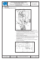
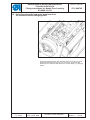
3 Montage
3.1 Nadelstangenhalter fixieren
– Seitendeckel aus Nähmaschinenoberteil demontieren und
sechstantige Schraube ausschrauben, die den Schmierdocht
an der Seite des Nadelstangenhalters (1) anhält.
– Zylinderstift (3) in den Maschinenarm (2) so einklopfen, dass
er etwa 3 mm hervortritt. Achtung auf die Buchse der
Fußstangenführung!
–
Mutter (4) an der Druckschraube (5) mit dem Kleber Loctite
638 nach Abbildung verkleben.
–
Halter (6) an den Stift im Nähmaschinenarm ansetzen und mit
der Druckschraube zum Nadelstangenhalter festziehen, der
am Nadellochmittelpunkt des Stichplatteneinsatzes
aufgestellt wird.
–
Danach die Schelle mit Docht (7) aufsetzen und die andere
Mutter (8) nachziehen.
Teile-Nr./ Part-No.:
0791 888702
Printed in Czech Republic
Ausgabe/Edition:
11. 2019
Anbauanleitung blokiert Nadeltransport
Teilesatz 0888 310134
Fitting Instructions for Needle Feed Locking
Kit 0888 310134
Blatt: von
Sheet: 2 from 8
Änderungsindex
Rev. index: 01.0
3-5

Teile-Nr./ Part-No.:
0791 888702
Printed in Czech Republic
Ausgabe/Edition:
11. 2019
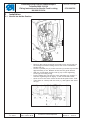
3.2 Aluminium-Oberhebel des Nadeltransports
an der Schwingungswelle des Nadelstangenhalters lockern
– Schraube M4 mit Unterlage aus dem Hebel (9) ausschrauben
und statt dieser die Druckschraube (10) anschrauben, damit
der Klemmnabe so ausspreizen, dass der Hebel and der
Welle (11) locker schwingt.
Anbauanleitung blokiert Nadeltransport
Teilesatz 0888 310134
Fitting Instructions for Needle Feed Locking
Kit 0888 310134
Blatt: von
Sheet: 3 from 8
Änderungsindex
Rev. index: 01.0

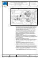
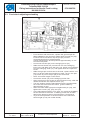
3.3 Transportkupplung anpassen und einstellen
– Bei Maschinen mit Minimotor den Rillenstift 9303 502990 für
den Minimotorhalter mit dem längeren Stift (22) so ersetzen.
Bei Maschinen mit Direktantrieb den Rillenstift (23) in die
entsprechende Bohrung in der Grundplatte einschlagen.
In beiden Fällen sollte der Stift etwa 17 mm von der linken
Seite der Grundplatte mm vorstehen.
– Die beiden Schrauben (20) an der Schwinghebel lockern.
– Bolzen der linken Transportkupplung-Zugstange aus der
Öffnung im Schwinghebel ausschieben und ihn in die
Öffnung (12) einsetzen, die sich am längsten von der
Schwingwelle (13) befindet, und mit der entsprechenden
Schraube nachziehen.
–
Bolzen der rechten Zugstange aus der Öffnung ausziehen,
bei Handradstellung 300° gegen einen neuen Bolzen (14)
austauschen, ins Teil (15) einsetzen, das gleichzeitig am Stift
(22) eingesetzt ist.
–
Nullstichlange am Stellrad einstellen.
–
Schraube (16) an der Schwingungsbewegungkulisse lockern.
–
Nach Ausschrauben der Schraube am Transportkuplungs-
körper den Nadelkolben in entsprechende Öffnung (17)
einschieben.
–
Nähmaschinen-Handrad so lange drehen, bis der
Nadelkolben in die Öffnung des Halters innerhalb der
Kupplung einfällt (schieben nach innen um etwa 5 mm).
–
Rechte Zugstange der Transportkupplung an Stift (22)
anlehnen und mit Schrauben (19), (20) und (16) nachziehen.
–
Bei Handradstellung 312° (332° für die Maschinen GLOBAL)
die Stellung von Transportkupplung-Umschaltungsexzenter
einstellen mit ihrem Strich gegenüber dem unteren Strich am
Umschaltungskeilstecker und befestigen.
–
Bei maximaler Stichlänge einwandfreie Funktion der
Transportkupplung prüfen (sie darf nicht drinnen anstoßen).
Teile-Nr./ Part-No.:
0791 888702
Printed in Czech Republic
Ausgabe/Edition:
11. 2019
Anbauanleitung blokiert Nadeltransport
Teilesatz 0888 310134
Fitting Instructions for Needle Feed Locking
Kit 0888 310134
Blatt: von
Sheet: 4 from 8
Änderungsindex
Rev. index: 01.0

Teile-Nr./ Part-No.:
0791 888702
Printed in Czech Republic
Ausgabe/Edition:
11. 2019
1 General information
Application for sewing machines 888 and 887 of M-Type series as
a optional equipment.
1.1 Add-on Kit
The complete kit needed for the needle feed lockinkg has
the order number 0888 310134 and is made of the following
components:
0888 310024 (15) Holder
0888 310030 (14) Pin
0888 120050 (6) Holder
9205 101898 (5) Threaded Pin (M4x12)
9231 000367 (4, 8) Nut
9840 120025 (7) Clip
9301 102451 (3) Cylinder Pin (6M6x8)
9205 102497 (10) Threaded Pin (M6x12)
9303 602880 (22) Grooved Pin (6x50) - for machines with
minimotor
9303 502990 (23) Grooved Pin (6x30) - for machines with
direct drive
2 Description and operation of equipment
Part set No. 0888 310134 is used to lock the needle feed in
shoe-making machines of M-Type series.
The change of a two-step feed for a one-step feed is achieved
through fixation of the needle bar holder against the machine
arm, by loosening of the bolted joint of the upper aluminum lever,
and fixation of the feeding clutch right pull rod (and thus also the
outer body of the clutch) with regard to the base plate.
The throat plate insert has No. 0888 200950 (category 100),
0888 200960 (200) or 0888 200970 (300).
Anbauanleitung blokiert Nadeltransport
Teilesatz 0888 310134
Fitting Instructions for Needle Feed Locking
Kit 0888 310134
Blatt: von
Sheet: 5 from 8
Änderungsindex
Rev. index: 01.0

Teile-Nr./ Part-No.:
0791 888702
Printed in Czech Republic
Ausgabe/Edition:
11. 2019
Anbauanleitung blokiert Nadeltransport
Teilesatz 0888 310134
Fitting Instructions for Needle Feed Locking
Kit 0888 310134
Blatt: von
Sheet: 6 from 8
Änderungsindex
Rev. index: 01.0
3 Installation
3.1 Needle bar holder fixation
3-5
– Remove the sewing machine head side cover and screw out
the hexagonal screw holding the oil wick on the needle bar
holder side (1).
–
Knock a cylinder pin (3) in the arm hole (2) so that it protrudes
approximately 3 mm. Beware of the foot bar guide sleeve!
–
With the Loctite 638, glue the nut (4) up on the regulating
screw (5) according to Fig.
–
Put the holder (6) onto the pin in the machine arm, and fix it
with the regulating screw tightly to the needle bar holder,
–
which is to be set at the center of the throat plate insert hole.
–
Then slide on a clamp with the wick (7), and tighten the other
nut (8).

Teile-Nr./ Part-No.:
0791 888702
Printed in Czech Republic
Ausgabe/Edition:
11. 2019
3.2 Unlocking of needle feed upper aluminum lever
on needle bar holder swinging shaft
– Unscrew the M4 screw with washer from the lever (9), and
screw the adjusting screw (10) in its place, by which the
bolted joint is split so that the lever on the s haft (11) swings
freely.
Anbauanleitung blokiert Nadeltransport
Teilesatz 0888 310134
Fitting Instructions for Needle Feed Locking
Kit 0888 310134
Blatt: von
Sheet: 7 from 8
Änderungsindex
Rev. index: 01.0

3.3 Feed clutch adjusting and setting
– For machines with minimotor, replace the grooved pin No.
9303 502990 for the minimotor holder with a longer pin (22).
For direct drive machines, tap the pin (23) into the
corresponding hole in the base plate.
In both cases the pin should protrude approximately 17 mm
from the base plate.
– Loosen two screws (20) on the swinging lever (21).
– Slide the feed clutch left pull rod bolt out of the swinging
lever hole, and slide it into the hole (12), which is most distant
from the swinging shaft (13), and tighten with the r espective
screw.
–
Slide the right pull rod bolt out of the hole; replace with a new
bolt (14) at the hand wheel position of 300°, put it in the part
(15), which is put on the pin (22) at the s ame time.
–
Set a zero stitch length on the wheel.
–
Loosen the screw (16) on the swinging motion link.
–
After screwing out the screw on the feed clutch body, slide the
needle shank into the respective hole (17).
–
Turn the s ewing machine hand wheel until the needle s hank
fits in the star hole inside the clutch (push inwards by
approximately 5 mm).
–
Lean the clutch feed right pull rod against the pin (22), and
tighten the screws (19), (20), and (16).
–
In the hand wheel position 312° (332° for machines GLOBAL),
set the switchover excenter of feeding clutch with its mark
against the bottom mark on the switchover V- fork and fix.
–
Try a smooth operation of the feed clutch at the maximum
stitch length (it may not collide inside).
Teile-Nr./ Part-No.:
0791 888702
Printed in Czech Republic
Ausgabe/Edition:
11. 2019
Anbauanleitung blokiert Nadeltransport
Teilesatz 0888 310134
Fitting Instructions for Needle Feed Locking
Kit 0888 310134
Blatt: von
Sheet: 8 from 8
Änderungsindex
Rev. index: 01.0
-
 1
1
-
 2
2
-
 3
3
-
 4
4
-
 5
5
-
 6
6
-
 7
7
-
 8
8


DURKOPP ADLER 888 Benutzerhandbuch
- Typ
- Benutzerhandbuch
in anderen Sprachen
- English: DURKOPP ADLER 888 User manual
Verwandte Artikel
-
DURKOPP ADLER 888 Benutzerhandbuch
-
-
-
-
Duerkopp Adler 867-M Benutzerhandbuch
-
-
-
-
DURKOPP ADLER 281 Benutzerhandbuch


