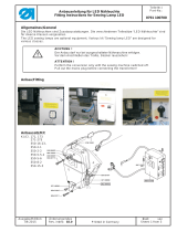
– Fl
uchtdorn 19 in die untere Buchse 18 einsetzen und
überprüfen, dass die obere Buchse 20 sich auf dem
Fluchtdorn geführt ohne jeden Kontakt zur Gehäusebohrung
einführen lässt.
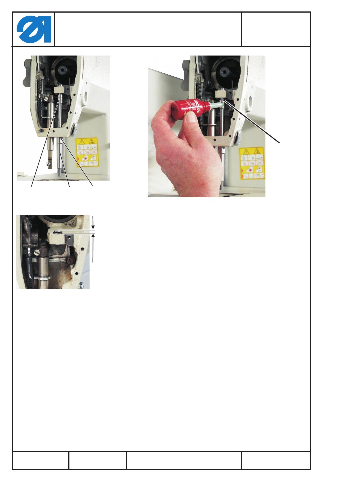
– Oberteil nach hinten klappen.
– Obere Nadelstangenbuchse 20 entfetten.
– Obere Nadelstangenbuchse 20 mit Loctite 603 gleichmäßig
benetzt unter Drehen in die Gehäusebohrung einschieben und
10 min aushärten lassen (Maß 0,8mm)
– Klebeergebnis / Flucht mit Fluchtdorn nach dem Aushärten
überprüfen.
Dorn muss ohne jeden Widerstand und ohne Anstoßen sehr
leicht bewegbar sein!
4 Demontierte Teile wieder einbauen.
– Kurbel auf Armwelle montieren, dabei Fadenhebel auf Mitte
Schlitz stellen und die Befestigungsschrauben sehr sauber auf
den Flächen der Armwelle zentrieren.
– Nadelstange (Kap 5. der Serviceanleitung beachten) einbauen
und mit etwas Fett an den Buchsen versorgen.
– Fadenhebellenkerbolzen s o wieder einsetzen, dass er ca.
0,5 mm hinter der Armfläche positioniert ist.
– Schleifenhubstellung des Greifers und Zeitpunkt der FA-Kurve
überprüfen und ggfs. korrigieren.
–
Kopfdeckel und Fadenhebelabdeckung montieren.
Reparaturanleitung Nadelstange
Bausatz (0281 801293)
Repairing Instructions Needle Bar
Kit (0281 801293)
Teile-Nr./ Part-No.:
0791 281771
Blatt: von
Sheet: 4 from 8
A
usgabe/Edition:
07.2017
Änderungsindex
Rev. i
ndex: 01.0
Printed in Germany
20 19 18
20
0
,
8
m
m