
Faktor Bildformat Bildformat Bildformat Bildformat
TV-Adapter
1″
2
/
3
″
1
/
2
″
1
/
3
″
0.35x 45,7 31,4 22,9 17,1
0.4 x 40 27,5 20 15
0.5 x 32 22 16 12
0.55x 29,1 20 14,5 10,9
0.63x 25,4 17,5 12,7 9,5
0.8 x 20 13,75 10 7,5
1 x 16 11 8 6
1.1 x 14,5 10 7,3
5,5
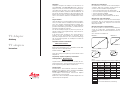
Abb. 2:
Monitor-Sehfeldgröße in Abhängigkeit von TV-Adapter und Bildformat
TV-Adapter
Anleitung
TV adapters
Instructions
Allgemeines
TV-Adapter ermöglichen die Adaption von Videokameras an
Leica DM R/DML- und DMIR/DM IL-Mikroskope. Zweck des
Adapters ist neben der soliden mechanischen Verbindung zwi-
schen Mikroskop und Kamera eine angepaßte Abbildung des
mikroskopischen Bildes (Sehfeld der Zwischenbildebene) auf
den Chip der benutzten CCD-Kamera. Die gebräuchlichen CCD-
Kameras weisen jedoch sehr unterschiedliche Chipgrößen auf,
woraus unterschiedliche Aufnahme- bzw. Bildformate resultie-
ren:
Adapter-Sortiment
Um in allen Fällen eine sinnvolle TV-Mikroprojektion zu gewähr-
leisten, sind daher mehrere TV-Adapter mit unterschiedlichen
festen oder variablen Vergrößerungsfaktoren verfügbar. Spe-
ziell für 3-Chip-Kameras sind Adapter mit 2stufiger Abbildung
(parallele Strahlenführung) anzuwenden, um Farbinhomogeni-
täten bzw. Geisterbilder zu vermeiden.
Aus diesem TV-Adapter-Angebot ist jeweils der passende, der
aktuellen Situation und Aufgabenstellung entsprechende TV-
Adapter zu selektieren.
In der Regel besteht der Wunsch, einen großen Anteil des
Sehfeldes auf den Fernseh-Monitor zu übertragen. Dieser
Anteil wird hauptsächlich durch den verwendeten Kameratyp
und den Vergrößerungsfaktor des TV-Adapters bestimmt. Es
gilt (siehe Abb. 2):
Abgebildetes Sehfeld auf dem Monitor =
Bilddiagonale der Kamera
Vergrößerungsfaktor des TV-Adapters
Beispiel für die Kombination einer
2
/
3
-Zoll-Kamera mit der Bild-
diagonale 11 mm und TV-Adapter 0.63x
Sehfeld auf Monitor =
11
= 17,5 mm
0,63
Für die Berechnung der Vergrößerung auf dem Monitor sind zu
multiplizieren:
Vergrößerung = Objektivvergrößerung x Tubusfaktor x
TV-Adapterfaktor x
Monitordiagonale
Bilddiagonale Kamera
Gegebenenfalls ist in diese Formel noch ein Faktor des Ver-
größerungswechslers- oder des Zoomsystems in die Rechnung
für die Vergrößerung auf dem Monitor einzubeziehen.
Adaptionsformen
Da Videokameras unterschiedliche mechanische Adaptions-
voraussetzungen aufweisen, werden TV-Adapter für C-mount-,
B-mount- oder F-mount-Adaption unterschieden.
C-mount-Adapter sind am meisten verbreitet. Die Adaption
erfolgt über das C-mount-Gewinde.
Bei B-mount- und F-mount-Adapter wird die Adaption über ein
spezielles Bajonett durchgeführt.
Montage der C-mount-Adapter
Die Videokamera ist zunächst auf den C-mount-Adapter aufzu-
schrauben. Beide Teile zusammen werden danach entspre-
chend der existierenden Mikroskopkonfiguration
• an den vertikalen Photostutzen des HC FSA Tubus
• an einen der beiden Ausgänge des Photostutzens HC 100/100
• an den TV-Ausgang des DMRD
• an den seitlichen TV-Ausgang des DMIR
aufgesetzt und mit der seitlichen Klemmschraube fixiert.
Montage der B- und F-mount-Adapter
Zunächst ist die Kamera auf den B- bzw. F-mount-Adapter auf-
zuschrauben, dann
auf den Bajonettstutzen aufzuriegeln. Die
Befestigung am Mikro
skop erfolgt wie vorher beim C-mount-
Adapter beschrieben.
Montage der Adapter für 2stufige Abbildung
Bei diesen Systemen ist zunächst der Basis-Adapter 0.5x mit
einem der gewünschten Sekundär-Adapter zusammenzu-
schrauben. Die weitere Prozedur verläuft wie bei den 1stufigen
Adaptern.
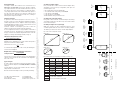
Abb. 1: Videokameras und Bildformate
Bildformat 1″
Bildformat
2
/
3
″
Bildformat
1
/
2
″
Bildformat
1
/
3
″
12,8 mm
6,4 mm
8,8 mm
4,8 mm
4,8 mm
6,6 mm
9,6 mm
3,6 mm
16 mm
8 mm
11 mm
5,5 mm
empfohlene Kombinationen
theoretische Kombinationen (nicht zulässig)

General information
TV adapters enable video cameras to be connected to Leica
DM R/DML and DMIR/DM IL microscopes. Besides establish-
ing a rigid mechanical connection between the microscope and
the camera, the purpose of the adapter is to adapt the micro-
scope image (field of view of the intermediate image plane) to
the chip of the CCD camera in use. However, commonly used
CCD cameras have extremely different chip sizes, resulting in
different photo and picture formats:
Selection of adapters
To guarantee useful TV microprojection in all cases, there is
therefore a choice of several TV adapters with different fixed or
variable magnification factors. Adapters with 2-stage imaging
(parallel light paths) should be used for 3 chip cameras to avoid
colour inhomogeneities or ghost images.
From this selection of TV adapters you need to select the
adapter according to the situation and your application.
Users usually want to transfer a large proportion of the field of
view to the TV screen. This proportion is usually determined by
the type of camera used and the magnification factor of the TV
adapter, according to the following formula (see Fig. 2):
Field of view imaged on the screen =
picture diagonal of camera
magnification factor of TV adapter
Example for the combination of a
2
/
3
inch camera with a picture
diagonal of 11 mm and TV adapter 0.63x
Field of view on screen =
11
= 17.5 mm
0.63
To calculate the magnification on the screen, the following fac-
tors have to be multiplied:
Magnification = objective magnification x tube factor x
TV adapter factor x
screen diagonal
camera picture diagonal
You may also need to incorporate a factor of the magnification
changer or zoom system into the calculation for the magnifica-
tion on the screen.
Types of adapter
As video cameras have different mechanical adapter mounts,
there are different adapters for C-mount, B-mount or F-mount
adaption.
C-mount adapters are the most common. Here the camera is
adapted via the C-mount thread.
B-mount and F-mount adapters need a special bayonet fitting.
Assembly of C-mount adapters
First, screw the video camera onto the C-mount adapter. Then,
depending on the microscope configuration, both parts are
mounted together onto
• the vertical photo port of the HC FSA tube
• one of the two exits of the photo port HC 100/100
• to the TV port of the DM RD
• to the side TV port of the DM IR
and fixed with the clamp screw at the side.
Assembly of B- and F-mount adapters
First, put the camera on the B- or F-mount adapter onto the bay-
onet fitting and then fix to the microscope as described above
for the C-mount adapter.
Assembly of adapters for 2-stage imaging
With these systems, the basic adapter 0.5x first has to be
screwed together with one of the chosen secondary adapters.
The further procedure is the same as for the simple adapters.
Fig. 1: Video cameras and picture formats
Leica Microsystems Wetzlar GmbH
Ernst-Leitz-Straße
D-35578 Wetzlar (Germany)
Tel. +49 (0) 6441-29 0
Fax +49 (0) 64 41-29 25 99
www.leica-microsystems.com
Copyright © Leica Microsystems Wetzlar GmbH Ernst-Leitz-Straße 35578 Wetzlar Germany 2001 Tel. (064 41) 29-0 Fax (0 6441) 29-25 99 LEICA and the Leica Logo are registered trademarks of Leica Technology BV.
Bestell-Nummern der Ausgaben in: Deutsch/Englisch 933 811 Sach-Nr. 540-065 Gedruckt auf chlorfrei gebleichtem Papier. I/01/FX/FD.H.
Image size 1″
Image size
2
/
3
″
Image size
1
/
2
″
Image size
1
/
3
″
12.8 mm
6.4 mm
8.8 mm
4.8 mm
4.8 mm
6.6 mm
9.6 mm
3.6 mm
16 mm
8 mm
11 mm
5.5 mm
Fig. 2: Monitor field of view depending on TV adapter and image size
0.35x 0.5x 0.63x 1x
C-mount
1″
C-mount
1
/
3
″
C-mount
1
/
2
″
C-mount
2
/
3
″
541 540
F-mount
1
/
2
″
541 541
F-mount
2
/
3
″
543 706
C-mount
1
/
2
″
543 702
B-mount
1
/
2
″
Sony
541 539
B-mount
2
/
3
″
Sony
541 512 541 511 541 537
Best.-Nr.
Order no.
541 510
Vario
0.33…1.6x
541 517
Vario
0.5…2.4x
541 518541 538
0.5x
1x
1x1x
C-mount
1
/
3
″;
1
/
2
″
B-mount
Sony
1
/
2
″
1.25x 1.25x
for single Chip Cameras
for 3 Chip Cameras
recommended combination
theoretical combination (not allowed)
Factor Image size Image size Image size Image size
TV adapter
1″
2
/
3
″
1
/
2
″
1
/
3
″
0.35x 45.7 31.4 22.9 17.1
0.4 x 40 27.5 20 15
0.5 x 32 22 16 12
0.55x 29.1 20 14.5 10.9
0.63x 25.4 17.5 12.7 9.5
0.8 x 20 13.75 10 7.5
1 x 16 11 8 6
1.1 x 14.5 10 7.3 5.5
-
 1
1
-
 2
2


Leica Microsystems DM IL LED Benutzerhandbuch
- Kategorie
- Mikroskope
- Typ
- Benutzerhandbuch
in anderen Sprachen
Verwandte Artikel
Andere Dokumente
-
Leica DMI3000B Benutzerhandbuch
-
-
Sharp DM4500P Benutzerhandbuch
-
-
Leica M-P (Typ 240) Bedienungsanleitung
-
Leica M10 Bedienungsanleitung
-
-
Motic SMZ161 Series Benutzerhandbuch
-
-
Leica TL2 Bedienungsanleitung