Pepperl+Fuchs UB800-18GM40A-I-V1 Bedienungsanleitung
- Typ
- Bedienungsanleitung

Ultraschall-Sensor
Ultrasonic Sensor
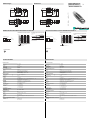
Abmessungen
Elektrischer Anschluss/Kurven/
Zusätzliche Informationen
Electrical Connection / Curves / Additional Information
Dimensions
Technische Daten
Technical data
UB800-18GM40A-I-V1
67,7
39,2
24,5
10
M12 x 1
M18 x 1
4
24
LED
-
67.7
39.2
24.5
10
M12 x 1
M18 x 1
4
24
LED
3 (BU)
1 (BN)
2 (WH)
4 (BK)
U
+ UB
Lerneingang
Analogausgang
- UB
Adernfarben gemäß EN 60947-5-2.
Normsymbol/Anschluss:
(Version I)
Steckverbinder V1
2
31
4
Abstand X [mm]
Charakteristische Ansprechkurve
Abstand Y [mm]
Kurve 1: ebene Platte 100 mm x 100 mm
Kurve 2: Rundstab, Ø 25 mm
0 200 400 600 800 1000 1200 1400
200
150
100
50
0
-50
-100
-150
-200
1
2
X
Y
Programmierung der Auswertegrenzen
Steigende Rampe
A1 < A2:
Fallende Rampe
A2 < A1:
Objektabstand
A1 -> ∞, A2 -> ∞: Detektion auf Objektanwesenheit
Objekt erkannt: 20 mA
kein Objekt erkannt: 4 mA
A1 A2
A2 A1
Programmed analogue output function
Rising ramp
A1 < A2:
Falling ramp
A2 < A1:
object range
A1 -> ∞, A2 -> ∞: Detection of object presence
Object detected: 20 mA
No object detected: 4 mA
A1 A2
A2 A1
Characteristic response curve
Distance X [mm]
Distance Y [mm]
Curve 1: flat surface 100 mm x 100 mm
Curve 2: round bar, Ø 25 mm
0 200 400 600 800 1000 1200 1400
200
150
100
50
0
-50
-100
-150
-200
1
2
X
Y
3 (BU)
1 (BN)
2 (WH)
4 (BK)
U
+ UB
Teach input
Analogue output
- UB
Core colours in accordance with EN 60947-5-2.
Standard symbol/Connections:
(version I)
Connector V1
2
31
4
Part. No.:
Date:
205341
12/09/2009 DIN A3 -> DIN
45-2510A
Doc. No.:
Allgemeine Daten
Erfassungsbereich 50 ... 800 mm
Einstellbereich 70 ... 800 mm
Blindzone 0 ... 50 mm
Normmessplatte 100 mm x 100 mm
Wandlerfrequenz ca. 255 kHz
Ansprechverzug ca. 100 ms
Anzeigen/Bedienelemente
LED grün Power on
LED gelb permanent gelb: Objekt im Auswertebereich
gelb blinkend: Lernfunktion, Objekt erkannt
LED rot permanent rot: Störung
rot blinkend: Lernfunktion, Objekt nicht erkannt
Elektrische Daten
Betriebsspannung UB10 ... 30 V DC , Welligkeit 10 %SS
Leerlaufstrom I0 20 mA
Eingang
Eingangstyp 1 Lerneingang
untere Auswertegrenze A1: -UB ... +1 V, obere Auswertegrenze A2: +4 V ... +UB
Eingangsimpedanz: > 4,7 k, Lernimpuls: 1 s
Ausgang
Ausgangstyp 1 Analogausgang 4 ... 20 mA, kurzschluss-/überlastfest
Voreinstellung Auswertegrenze A1: 70 mm Auswertegrenze A2: 800 mm
Auflösung 0,4 mm bei max. Erfassungsbeich
Kennlinienabweichung ± 1 % des Endwertes
Reproduzierbarkeit ± 0,5 % des Endwertes
Lastimpedanz 0 ... 300 bei UB > 10 V;
0 ... 500 bei UB > 15 V
Temperatureinfluss ± 1,5 % des Endwertes
Umgebungsbedingungen
Umgebungstemperatur -25 ... 70 °C (248 ... 343 K)
Lagertemperatur -40 ... 85 °C (233 ... 358 K)
Mechanische Daten
Schutzart IP67
Anschluss Gerätestecker V1 (M12 x 1), 4-polig
Material
Gehäuse Messing, vernickelt
Wandler Epoxidharz/Glashohlkugelgemisch; Schaum Polyurethan, Deckel PBT
Masse 25 g
Normen- und Richtlinienkonformität
Normenkonformität
Normen EN 60947-5-2:2007
IEC 60947-5-2:2007
General specifications
Sensing range 50 ... 800 mm
Adjustment range 70 ... 800 mm
Unusable area 0 ... 50 mm
Standard target plate 100 mm x 100 mm
Transducer frequency approx. 255 kHz
Response delay approx. 100 ms
Indicators/operating means
LED green Power on
LED yellow permanently yellow: object in the evaluation range
yellow, flashing: program function, object detected
LED red permanently red: Error
red, flashing: program function, object not detected
Electrical specifications
Operating voltage UB10 ... 30 V DC , ripple 10 %SS
No-load supply current I0 20 mA
Input
Input type 1 program input
lower evaluation limit A1: -UB ... +1 V, upper evaluation limit A2: +4 V ... +UB
input impedance: > 4.7 k, pulse duration: 1 s
Output
Output type 1 analogue output 4 ... 20 mA, short-circuit/overload protected
Default setting evaluation limit A1: 70 mm evaluation limit A2: 800 mm
Resolution 0.4 mm at max. sensing range
Deviation of the characteristic curve ± 1 % of full-scale value
Repeat accuracy ± 0.5 % of full-scale value
Load impedance 0 ... 300 at UB > 10 V;
0 ... 500 &Omega at UB > 15 V
Temperature influence ± 1.5 % of full-scale value
Ambient conditions
Ambient temperature -25 ... 70 °C (248 ... 343 K)
Storage temperature -40 ... 85 °C (233 ... 358 K)
Mechanical specifications
Protection degree IP67
Connection V1 connector (M12 x 1), 4-pin
Material
Housing brass, nickel-plated
Transducer epoxy resin/hollow glass sphere mixture; foam polyurethane, cover PBT
Mass 25 g
Compliance with standards and directives
Standard conformity
Standards EN 60947-5-2:2007
IEC 60947-5-2:2007

Adressen / Addresses / Adresses / Direcciónes / Indirizzi
Contact Pepperl+Fuchs GmbH · 68301 Mannheim · Germany · Tel. +49 621 776-4411 · Fax +49 621 776-27-4411 · E-mail: [email protected]l-fuchs.com
Worldwide Headquarters: Pepperl+Fuchs GmbH · Mannheim · Germany · E-mail: info@de.pepperl-fuchs.com
USA Headquarters: Pepperl+Fuchs Inc. · Twinsburg · USA · E-mail: fa-in[email protected]om
Asia Pacific Headquarters: Pepperl+Fuchs Pte Ltd · Singapore · E-mail: [email protected]perl-fuchs.com · Company Registration No. 199003130E
For more contact-adresses refer to the catalogue or internet: http://www.pepperl-fuchs.com
Adjusting the evaluation limits
The ultrasonic sensor features an analogue output with two teachable evaluation limits. These are set by applying the supply voltage -UB or
+UB to the TEACH-IN input. The supply voltage must be applied to the TEACH-IN input for at least 1 s. LEDs indicate whether the sensor has
recognised the target during the TEACH-IN procedure. The lower evaluation limit A1 is taught with -UB, A2 with +UB.
Two different output functions can be set:
1. Analogue value increases with rising distance to object (rising ramp)
2. Analogue value falls with rising distance to object (falling ramp)
TEACH-IN rising ramp (A2 > A1)
- Position object at lower evaluation limit
- TEACH-IN lower limit A1 with - UB
- Position object at upper evaluation limit
- TEACH-IN upper limit A2 with + UB
TEACH-IN falling ramp (A1 > A2):
- Position object at lower evaluation limit
- TEACH-IN lower limit A2 with + UB
- Position object at upper evaluation limit
- TEACH-IN upper limit A1 with - UB
Default setting
A1: unusable area
A2: nominal sensing range
Mode of operation: rising ramp
LED Displays
Displays in dependence on operating mode Red LED Yellow LED
TEACH-IN evaluation limit
Object detected
No object detected
Object uncertain (TEACH-IN invalid)
off
flashes
on
flashes
off
off
Normal mode (evaluation range) off on
Fault on previous state
Einstellen der Auswertegrenzen
Der Ultraschallsensor verfügt über einen Analogausgang mit zwei einlernbaren Auswertegrenzen. Diese werden durch Anlegen der
Versorgungsspannung -UB bzw. +UB an den Lerneingang eingestellt. Die Versorgungsspannung muss mindestens 1 s am Lerneingang
anliegen. Während des Einlernvorgangs wird mit den LEDs angezeigt, ob der Sensor das Target erkannt hat. Mit -UB wird die untere
Auswertegrenze A1 und mit +UB die obere Auswertegrenze A2 eingelernt.
Es sind zwei verschiedene Ausgangsfunktionen einstellbar:
1. Analogwert steigt mit zunehmendem Objektabstand (steigende Rampe)
2. Analogwert sinkt mit zunehmendem Objektabstand (fallende Rampe)
Einlernen der steigenden Rampe (A2 > A1)
- Objekt an unterer Auswertegrenze positionieren
- Untere Grenze A1 mit -UB einlernen
- Objekt an oberer Auswertegrenze positionieren
- Obere Grenze A2 mit +UB einlernen
Einlernen der fallenden Rampe (A1 > A2)
- Objekt an unterer Auswertegrenze positionieren
- Untere Grenze A2 mit +UB einlernen
- Objekt an oberer Auswertegrenze positionieren
- Obere Grenze A1 mit -UB einlernen
Voreinstellung
A1: Nahbereich
A2: Nennabstand
Wirkungsrichtung: steigende Rampe
LED-Anzeige
Anzeigen in Abhängigkeit des Betriebszustandes LED rot LED gelb
Auswertegrenze einlernen:
Objekt erkannt
kein Objekt erkannt
Objekt unsicher (Einlernen ungültig)
aus
blinkt
ein
blinkt
aus
aus
Normalbetrieb (Auswertebereich) aus ein
Störung ein letzter Zustand
-
 1
1
-
 2
2


Pepperl+Fuchs UB800-18GM40A-I-V1 Bedienungsanleitung
- Typ
- Bedienungsanleitung
in anderen Sprachen
Verwandte Artikel
-
Pepperl+Fuchs UB120-12GM-I-V1 Bedienungsanleitung
-
-
-
-
-
-
-
-
-