Pepperl+Fuchs UB500-F42-I-V15 Bedienungsanleitung
- Typ
- Bedienungsanleitung

Ultraschall-Sensor
Ultrasonic sensor
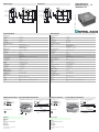
Abmessungen
Technische Daten Technical data
Elektrischer Anschluss Kurven/
Zusätzliche Informationen
Electrical connection Curves/additional information
Dimensions
UB500-F42-I-V15
Folientastatur
LED-Fenster
7,5
52,5
15,5
5,2
10
10
5
34
15
M12x1
80
65
80
65
16
34
A1A2
TEACH IN
MODE SET
-
Membrane keys
LED window
7.5
52.5
15.5
5.2
10
10
5
34
15
M12x1
80
65
80
65
16
34
A1A2
TEACH IN
MODE SET
Allgemeine Daten
Erfassungsbereich 30 ... 500 mm
Einstellbereich 50 ... 500 mm
Blindzone 0 ... 30 mm
Normmessplatte 100 mm x 100 mm
Wandlerfrequenz ca. 390 kHz
Ansprechverzug ca. 50 ms
Anzeigen/Bedienelemente
LED grün permanent grün: Power on
LED gelb permanent: Objekt im Auswertebereich
blinkend: Lernfunktion
LED rot Normalbetrieb: "Störung"
Lernfunktion: kein Objekt erkannt
Elektrische Daten
Betriebsspannung 10 ... 30 V DC , Welligkeit 10 %SS
Leerlaufstrom I0≤ 50 mA
Ein-/Ausgang
Synchronisation bidirektional
0-Pegel: -UB...+1 V
1-Pegel: +4 V...+UB
Eingangsimpedanz: > 12 KΩ
Synchronisationsimpuls: ≥ 100 µs, Synchronisationsimpulspause: ≥ 2 ms
Synchronisationsfrequenz
Gleichtaktbetrieb ≤ 95 Hz
Multiplexbetrieb ≤ 95/n Hz, n = Anzahl der Sensoren
Ausgang
Ausgangstyp 1 Analogausgang 4 ... 20 mA
Auflösung 0,2 mm bei max. Erfassungsbereich
Kennlinienabweichung ± 1 % des Endwertes
Reproduzierbarkeit ± 0,1 % des Endwertes
Lastimpedanz 0 ... 300 Ω
Temperatureinfluss ± 1 % des Endwertes
Normenkonformität
Normen EN 60947-5-2
Umgebungsbedingungen
Umgebungstemperatur -25 ... 70 °C (248 ... 343 K)
Lagertemperatur -40 ... 85 °C (233 ... 358 K)
Mechanische Daten
Schutzart IP54
Anschluss Gerätestecker V15 (M12 x 1), 5-polig
Material
Gehäuse PBT
Wandler Epoxidharz/Glashohlkugelgemisch; Schaum Polyurethan, Deckel PBT
Masse 140 g
General specifications
Sensing range 30 ... 500 mm
Adjustment range 50 ... 500 mm
Unusable area 0 ... 30 mm
Standard target plate 100 mm x 100 mm
Transducer frequency approx. 390 kHz
Response delay approx. 50 ms
Indicators/operating means
LED green permanently green: Power on
LED yellow permanent: object in evaluation range
flashing: TEACH-IN function
LED red normal operation: "fault"
TEACH-IN function: no object detected
Electrical specifications
Operating voltage 10 ... 30 V DC , ripple 10 %SS
No-load supply current I0≤ 50 mA
Input/Output
Synchronisation bi-directional
0 level -UB...+1 V
1 level: +4 V...+UB
input impedance: > 12 KOhm
synchronisation pulse: ≥ 100 µs, synchronisation interpulse period: ≥ 2 ms
Synchronisation frequency
Common mode operation ≤ 95 Hz
Multiplex operation ≤ 95/n Hz, n = number of sensors
Output
Output type 1 analogue output 4 ... 20 mA
Resolution 0,2 mm for max. detection range
Deviation of the characteristic curve ± 1 % of full-scale value
Repeat accuracy ± 0,1 % of full-scale value
Load impedance 0 ... 300 Ohm
Temperature influence ± 1 % of full-scale value
Standard conformity
Standards EN 60947-5-2
Ambient conditions
Ambient temperature -25 ... 70 °C (248 ... 343 K)
Storage temperature -40 ... 85 °C (233 ... 358 K)
Mechanical specifications
Protection degree IP54
Connection connector V15 (M12 x 1), 5 pin
Material
Housing PBT
Transducer epoxy resin/hollow glass sphere mixture; foam polyurethane, cover PBT
Mass 140 g
Normsymbol/Anschluss:
(Version I)
Lerneingang
Sync.
Analogausgang
Adernfarben gemäß EN 60947-5-2.
1
2
4
3
5
+ UB
- UB
(BN)
(WH)
(GY)
(BK)
(BU)
U
Steckverbinder V15
2
31
45
Abstand X [m]
Charakteristische Ansprechkurve
Abstand Y [m]
breite Schallkeule
schmale Schallkeule
ebene Platte 100 mm x 100 mm
X
Y
Rundstab, Ø 25 mm
0,2
0,1
0,0
-0,1
-0,2
0,0 0,2 0,4 0,6 0,8 1,0
A1A1
A1 = 0
A2
A2
A1 A2
Programmierung der Auswertegrenzen
Objektabstand
Steigende Rampe
Fallende Rampe
Blindzone
Nullpunktsgerade
Montagehilfen
MH 04-3505
MHW 11
Prozessanzeige- und Steuergerät
DA5-IU-2K-V
Kabeldosen *)
V15-G-2M-PVC
V15-W-2M-PUR
*) Weitere Kabeldosen finden Sie im
Abschnitt „Zubehör“.
Zubehör
A1A1
A1 = 0
A2
A2
A1 A2
Analogue output programmation
Object distance
Rising ramp
Falling ramp
Unusable area
Zero line
Characteristic response curve
Distance X [m]
Distance Y [m]
wide sonic beam
narrow sonic beam
Flat surface 100 mm x 100 mm
Round bar, Ø 25 mm
0.2
0.1
0.0
-0.1
-0.2
0.0 0.2 0.4 0.6 0.8 1.0
Mounting aids
MH 04-3505
MHW 11
Process indication and control unit
DA5-IU-2K-V
Cable sockets *)
V15-G-2M-PVC
V15-W-2M-PUR
*) For additional cable sockets see section
„Accessories“.
Accessories
Standard symbol/Connections:
(version I)
Teaching input
Sync.
Analog output
Core colours in accordance with EN 60947-5-2.
1
2
4
3
5
+ UB
- UB
(BN)
(WH)
(GY)
(BK)
(BU)
U
Connector V15
2
31
45
Part. No.:
Date:
133978
06/21/2005 DIN A3 -> DIN
45-1482
Doc. No.:

Hinweise Notes
Adressen / Addresses / Adresses / Direcciónes / Indirizzi
Deutschland: Pepperl+Fuchs GmbH, Königsberger Allee 87, 68307 Mannheim, Tel. +49 (0) 621 776-1111, Fax +49 (0) 621 776-1000, fa-[email protected]rl-fuchs.com
Great Britain: Pepperl+Fuchs (GB) Ltd., 77 Riponden Road, OLDHAM OL1 4EL, Lancashire, Tel. (161) 6 33 64 31, Telefax (161) 6 28 31 14, [email protected]fuchs.com
USA: Pepperl+Fuchs Inc., 1600 Enterprise Parkway, Twinsburg, Ohio 44087, Cleveland-USA, Tel. (330) 4 25 35 55, Telefax (330) 4 25 93 85, [email protected]
France: Pepperl+Fuchs SARL, 12 Avenue des Tropiques - Les Ulis, 91955 COURTABOEUF CEDEX, Tel. (1) 60 92 13 13, Telefax (1) 60 92 13 25, commer[email protected]uchs.com
España Pepperl+Fuchs S.A., Txori-Erri Etorbidea 46, Pol. Izarza, 48150 SONDIKA (Vizcaya), Tel. (4) 4 53 50 20, Telefax (4) 4 53 51 80, [email protected]-fuchs.com
Italia Pepperl+Fuchs ELCON S.r.l., Via delle Industrie, 4, 20050 MEZZAGO (Milano), Tel. (039) 6 29 21, Telefax (039) 6 29 22 40, [email protected]pperl-fuchs.com
Singapore Pepperl+Fuchs Pte Ltd., P+F Building, 18 Ayer Rajah Crescent, Singapore 139942, Tel. (65) 67 79 90 91, Telefax (65) 68 73 16 37, [email protected]-fuchs.com
For more contact-adresses refer to the catalogue or internet: http://www.pepperl-fuchs.com
Funktionsbeschreibung
Der Sensor kann über 2 Tasten an der Gehäuseseite vollständig parametriert werden. Ein besonderes Merkmal dieses Sensors ist die
Möglichkeit die Ultraschall-Keulenbreite an die Umgebungsbedingungen am Einsatzort des Sensors anzupassen.
Voreinstellungen
A1: Nahbereich
A2: Nennabstand
steigende Rampe
breite Ultraschall-Keule
Einlernen der Auswertegrenzen:
Mit den Auswertegrenzen wird die Kennlinie und damit der Arbeitsbereich des Analogausgangs festgelegt.
Das Einlernen der Auswertegrenze A2 erfolgt analog zu obiger Beschreibung mittels Taste A2.
Alternativ können die Auswertegrenzen auch elektrisch, mittels des Lerneingangs eingestellt werden. Für das Einlernen der Auswertegrenze
A1 ist der Lerneingang mit -UB zu verbinden, für die Auswertegrenze A2 mit +UB. Das Speichern der gelernten Werte erfolgt beim Abtrennen
des Lerneingangs.
Ein Einlernen der Auswertegrenzen ist nur innerhalb der ersten 5 Minuten nach Zuschalten der Spannungsversorgung möglich. Sollen die
Auswertegrenzen zu einem späteren Zeitpunkt verändert werden, so ist dies erst nach einem erneuten Power On möglich.
Parametrierung der Ausgangsfunktion und der Ultraschall-Keulenbreite
Wenn die Taste A1 während des Zuschaltens der Spannungsversorgung gedrückt und danach noch für 1 s gehalten wird, so geht der Sensor in die zweistufige Parame-
trierung der Betriebsmodi.
Stufe 1, Parametrierung der Ausgangsfunktion
Ausgehend von der zuletzt parametrieten Ausgangsfunktion, können durch kurzes Betätigen der Taste A2 nacheinander die möglichen
Ausgangsfunktionen angewählt werden. Diese werden durch die Blinkfolge der grünen LED angezeigt.
In der Einstellung „Nullpunktsgerade“ wird die Auswertegrenze A1 (siehe Einlernen der Auswertegrenzen) fest auf 0 gelegt. Die Auswertegrenze A2 bestimmt die Steilheit
der Ausgangskennlinie.
Mit dem Drücken der Taste A1 für 2 Sekunden wird die gewählte Ausgangsbetriebsart gespeichert, der Parametriervorgang abgeschlossen und der Sensor kehrt in den
Normalmodus zurück. Drücken Sie die Taste A1 statt dessen nur kurz, so gelangen Sie in Stufe 2 (Parametrierung der Ultraschall-Keulenbreite).
Stufe 2, Parametrierung der Ultraschall-Keulenbreite
In Stufe 2 kann die Breite der Ultraschall-Keule an die Erfordernisse der jeweiligen Applikation angepasst werden.
Ausgehend von der zuletzt parametrieten Keulenbreite, können durch kurzes Betätigen der Taste A2 nacheinander die möglichen
Keulenbreiten angewählt werden. Diese werden durch die Blinkfolge der roten LED angezeigt.
Mit dem Drücken der Taste A1 für 2 Sekunden wird die gewählte Keulenform gespeichert, der Parametriervorgang abgeschlossen und der Sensor kehrt in den Normal-
modus zurück. Drücken Sie die Taste A1 statt dessen nur kurz, so gelangen Sie zurück in Stufe 1 (Parametrierung der Ausgangsfunktion).
Wird die Parametrierung nicht binnen 5 Minuten abgeschlossen (Drücken der Taste A1 für 2 Sekunden), so bricht der Sensor den Parametriermodus mit unveränderten
Einstellungen ab.
Synchronisation
Zur Unterdrückung gegenseitiger Beeinflussung verfügt der Sensor über einen Synchronisationsanschluss. Ist dieser unbeschaltet, arbeitet
der Sensor mit einer intern erzeugten Taktrate. Eine Synchronisation mehrerer Sensoren kann auf folgende Arten erreicht werden.
Fremdsynchronisation:
Der Sensor kann durch äußeres Anlegen einer Rechteckspannung synchronisiert werden. Ein Synchronisationsimpuls am
Synchronisationseingang führt zur Durchführung eines Messzyklus. Die Impulsbreite muss größer 100 µs sein. Der Messzyklus wird mit der
fallenden Flanke gestartet. Ein Low Pegel > 1 s oder ein offener Synchronisationseingang führt zum Normalbetrieb des Sensors. Ein High
Pegel am Synchronisationseingang deaktiviert den Sensor.
Zwei Betriebsarten sind möglich
- Mehrere Sensoren werden mit dem selben Synchronisationssignal angesteuert. Die Sensoren arbeiten im Gleichtakt.
- Die Synchronisationsimpulse werden zyklisch nur jeweils einem Sensor zugeführt. Die Sensoren arbeiten im Multiplexbetrieb.
Selbstsynchronisation:
Die Synchronisationsanschlüsse von bis zu 5 Sensoren mit der Möglichkeit der Selbstsynchronisation werden miteinander verbunden. Diese
Sensoren arbeiten nach dem Einschalten der Betriebsspannung im Multiplexbetrieb. Der Ansprechverzug erhöht sich entsprechend der
Anzahl der zu synchronisierenden Sensoren. Während des Einlernens kann nicht synchronisiert werden und umgekehrt. Zum Einlernen der
Schaltpunkte müssen die Sensoren unsynchronisiert betrieben werden.
Hinweis:
Wird die Möglichkeit zur Synchronisation nicht genutzt, so ist der Synchronisationseingang mit Masse (0V) zu verbinden oder der Sensor mit
einem V1-Anschlusskabel (4-polig) zu betreiben.
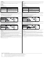
Einlernen der Auswertegrenze A1 mit der Taste A1
Taste A1 > 2 s drücken Der Sensor geht in den Lernmodus für Auswertegrenze A1
Zielobjekt in gewünschtem Ab-
stand positionieren
Der Sensor zeigt durch schnelles Blinken der gelben LED
an, dass das Zielobjekt erkannt wird. Bei nicht erkanntem
Objekt blinkt die rote LED.
Taste A1 kurz drücken Der Sensor beendet den Einlernvorgang der Auswerte-
grenze A1 und speichert diesen Wert nichtflüchtig ab. Bei
unsicherem Objekt (rote LED leuchtet unregelmäßig) ist
der eingelernt Wert ungültig. Der Einlernmodus wird ver-
lassen.
Betriebsart Blinkfolge der grünen LED Taste A 2
steigende Rampe
fallende Rampe
Nullpunktsgerade
Keulenbreite Blinkfolge der roten LED Taste A 2
schmale Keule
mittlere Keule
breite Keule
Pause
Pause
Pause
Pause
Pause
Pause
Functional Description
The sensor may be completely parameterised via two keys on the side panel of the housing. As a special feature provided by this sensor, the
ultrasound beam width may be adapted to the environmental conditions at the place of operation of the sensor.
Default settings
A1: Local range
A2: Nominal distance
rising edge
wide ultrasound beam
Specifying the evaluation limits:
The evaluation limits determine the characteristic line and the working range of the analog output.
The A2 evaluation limit is specified via the A2 key, analogous to the description above.
Alternatively, the evaluation limits may also be specified electrically via the learn input. To specify the A1 evaluation limit, the learn input must
be connected to
-UB; to specify the A2 evaluation limit, it must be connected to +UB. Specified values are saved upon the disconnection from the learn input.
Evaluation limits may only be specified within the first 5 minutes after Power on. To modify the evaluation limits later, the user may specify the
desired values only after a new Power On.
Proceed as follows to parameterise the output function and the ultrasound beam width:
Press the A1 key during Power on and hold down the key for another second to ensure that the sensor starts the two-step parameterisation of the operating modes.
Step 1, parameterisation of the output function
The output function parameterised last is displayed. All output functions available may be selected via consecutive, brief strokes of the A2 key.
These strokes are visualised via short flashes of the green LED.
The "Zero point straight line“ setting fixedly specifies the A1 evaluation limit to 0 (see specification of the evaluation limits). The A2 evaluation limit determines the steepness
of the output characteristic line.
Hold down the A1 key for 2 seconds to save the selected output mode, complete the parameterisation and ensure that the sensor returns to normal mode. If you briefly
press the A1 key, Step 2 is entered (parameterisation of the ultrasound beam width).
Step 2, parameterisation of the ultrasound beam width
Via Step 2, the ultrasound beam width may be adapted to the requirements of the corresponding application.
The beam width parameterised last is displayed first. Available beam width settings may be selected via consecutive, brief strokes of the A2
key. These strokes are visualised via the flash sequence of the red LED.
Hold down the A1 key for 2 seconds to save the selected beam shape, terminate the parameterisation and ensure that the sensor returns to normal mode. Briefly press
the A1 key to return to Step 1 (parameterisation of the output function).
If the parameterisation mode is not terminated within 5 minutes (hold down the A1 key for 2 seconds), the sensor aborts this mode without modifying the settings.
Synchronisation
The sensor provides a synchronisation port to suppress mutual influencing. If this port has not been connected, the sensor works at an
internally generated cycle rate. Several sensors may be synchronised via the following options.
External synchronisation:
The sensor may be synchronised via the external application of a square wave voltage. A synchronisation pulse on the synchronisation input
initiates a measuring cycle. The pulse width must be greater than 100 µs. The measuring cycle is started with the falling edge. A low level > 1
s or an open synchronisation input initiate the transition to normal sensor mode. A high level on the synchronisation input deactivates the
sensor.
Two modes are possible:
- Several sensors are controlled via the same synchronisation signal. The sensors work in common mode.
- The synchronisation pulses are forwarded at cyclic intervals to respectively one single sensor. The sensors work in multiplex mode.
Self-synchronisation:
The synchronisation ports of up to 5 sensors suitable for self-synchronisation are connected to each other. These sensors work in multiplex
mode after Power on. The On delay increases depending on the number of sensors to be synchronised. While the learn mode is active, no
synchronisation is possible (and vice-versa). To specify the switching points, the sensors must be operated in non-synchronised mode.
Note:
If the synchronisation option is not used, the synchronisation input must be connected to ground (0V) or the sensor must be operated with a
(4-pole) V1 connecting cable.
Specifying the A1 evaluation limit by pressing the A1 key
Holding down the A1key > 2 sec-
onds
The sensor switches to learn mode and the user may spec-
ify the A1 evaluation limit
Position the target object at the
desired distance
The yellow LED of the sensor flashes fast to indicate that
the target object is recognised. The red LED flashes if the
object is not recognised.
Briefly pressing the A1 key The sensor terminates the specification of the A1 evalua-
tion limit and saves it as a non-volatile value. The specified
value is invalid if the object is uncertain (i.e. the red LED
lights up at irregular intervals). The learn mode is exited.
Operating mode Flash sequence of the green LED A2 key
Rising edge
Falling edge
Zero point straight line
Beam width Flash sequence of the red LED A2 key
Small beam
Medium beam
Large beam
pause
pause
pause
pause
pause
pause
-
 1
1
-
 2
2


Pepperl+Fuchs UB500-F42-I-V15 Bedienungsanleitung
- Typ
- Bedienungsanleitung
in anderen Sprachen
Verwandte Papiere
-
Pepperl+Fuchs UB2000-F42S-U-V15 Bedienungsanleitung
-
-
-
-
-
-
-
-
-