CARLO GAVAZZI WM4096 Benutzerhandbuch
- Kategorie
- Komfortbeleuchtung
- Typ
- Benutzerhandbuch

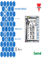
Instruction Manual
Display, Programming
Modular system
Class 0.2 A/V

CARLO GAVAZZI
Automation Components
1
Thank you for choosing our products
WM40 96:
• High accuracy (class 0.2 A/V);
• High calculation performances for a fast analysis of
the signal (FFT up to the 32nd harmonics);
• high connection capabilities.
WM40-96 is the state-of-the-art tecnological answer to
your needs of power quality analysis.
Moreover, you can count on a ISO9001/VISION
2000 certified company structure, an experience
of many years and a wide-spread presence both
in Europe and all over the world. All this in order
to guarantee the customer with a top-quality service
and the best products.
Welcome in Carlo Gavazzi and our compliments
for your choice. You can evaluate the complete
range of our products on the CARLO GAVAZZI
web-site:
www.gavazzi-automation.com

I
I
N
N
T
T
R
R
O
O
D
D
U
U
C
C
T
T
I
I
O
O
N
N
T
T
O
O
W
W
M
M
4
4
0
0
CARLO GAVAZZI
Automation Components
2
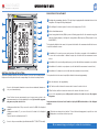
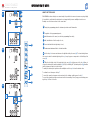
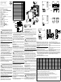
DESCRIPTION OF THE INSTRUMENT
Reading and programming optical port. The optical port is equipped with a detachable device for the
integration of the magnetic fixing reading head.
Colour Bar-graf to show at a glance the status of the single phases L1-L2-L3.
Active virtual alarms warners.
Current energy drain indicator (kWh) by means of flashing, proportional to the measured energy (the
higher the flashing frequency, the higher the energy drained. Max. frequency 16Hz pursuant to stan-
dard EN5047-1).
The keyboard is divided into two areas, the top area is dedicated to the measurements with direct access
to specific visualization screens.
Visualization of the counters screens: each pressure of the button corresponds to the visualization of
a screen with counters related to different energies (see the table with the measurement screens
below).
Visualization of the current voltage and frequency (see the table with the measurement screens below).
Visualization of the instant cos
ϕ and powers (see the table with the measurement screens below).
Visualization of the harmonics (see the table with the measurement screens below).
The keyboard in the bottom area is especially dedicated to instrument programming.
Exits the submenus, exits programming.
“Up” button, enables to browse the menus and to increase the values to be set.
“Down” button, enables to browse the menus and to decrease the values to be set.
Access to the programming menu:
hold pressed for at least 2 seconds to access the program-
ming menu.
In measurement mode, buttons 8 and 9 enable to display the MAX and dmd values of the displayed
variables.
The buttons are enhanced touch buttons. To check their actual engagement, a specific icon on the
display turns on each time a button is pressed.
12
11
10
9
8
7
6
5
4
3
2
1
ADDITIONAL FUNCTIONS OF THE BUTTONS
The buttons featuring a double icon have two functions, to access the secondary function,
hold pressed for a long time the button corresponding to the desired secondary function.
Access to the instrument information screens: reference standards, firmware ver-
sion, year of manufacturing.
“Home” button: from any measurement screen, from any menu, returns to the
main measurement screen (customizable by the user).
If you are in the program-
ming menu, any data entered is lost.
Holding pressed the button 10, you access the reset of the MAX of the displayed
variables.
Holding pressed button 11, you access the reset of the dmd's of the displayed
variables.
The reset must be confirmed by button 12.
Access to the pr
ocess variables (only with dedicated: M A T P, M A T P N module).
W
e r
ecommend using your for
efinger to activate the touch buttons.
3
4
5
6
7
8
9
10
11
12
1
2

CARLO GAVAZZI
Automation Components
3
I
I
N
N
T
T
R
R
O
O
D
D
U
U
C
C
T
T
I
I
O
O
N
N
T
T
O
O
W
W
M
M
4
4
0
0
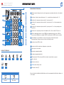
DESCRIPTION OF THE DISPLAY
Graphic bar which displays the active and the apparent power drained with relation to the installed
power.
Indications of inductive phase displacement L, -L, or capacitive phase displacement C, -C.
Indication of the measurement phase-neutral L1 or phase-phase L12.
Indication of the measurement phase-neutral L2 or phase-phase L23 or of the asymmetry phase-
phase VLL.
Indication of the measurement phase-neutral L3 or phase-phase L31 or of the asymmetry phase-
neutral VLn.
Indication of the engineering unit and of the multiplier: k, M, V, W, A, var (VAr), PF (Pf), Hz, An.
ALR: the alarm display function is active. PROG: the programming function is active. LOG: it is
active when the LOG function is enabled. EVENT: it is active when the EVENT function is enabled.
Area dedicated to the visualization of counters, text messages, date and time (format:
dd.mm.yy/hh:mm). Energy counters (see table on the following screen).
Indication of: dmd, THD% or Max.
Indicates that all the instant values displayed are system values.
Phase sequence error alarm.
Instrument programming enabled.
Instrument programming disabled.
Data transmission (TX) and reception (RX), via network communication, in progress.
Gas counter (m
3
).
Hot water counter (m
3
).
+ kWh, remote heating counter.
Cold water counter (m
3
).
Notes: the display is backlighted with lighting time and colour programmable from 0 minutes (always on)
to 255 minutes.
17
16
16
15
14
13
12
11
10
9
8
7
6
5
4
3
2
1
ICONS OF THE DISPLAY
1
3
4
5
6
10 11 12 13 14
ALARM SETPOINT
Up alarm. Down alarm.
7
8
9
2
LINE 1LINE 2LINE 3LINE 4LINE 5
15
16 17

I
I
N
N
T
T
R
R
O
O
D
D
U
U
C
C
T
T
I
I
O
O
N
N
T
T
O
O
W
W
M
M
4
4
0
0
CARLO GAVAZZI
Automation Components
4
01
02
03
c
d
e
HOW TO SET THE VALUES
With WM40 the values setting is even more simple, it is possible to increase or decrease every single digit,
it is possible to easily obtain the wished value or change directly from one multiplier to another one.
Example: use of the menu relevant to the current ratio.
During the programming phase the instrument provides useful information:
recognition of the programming mode;
identifier number of the menu (see also the programming flow chart);
edit, identification of the line subject to set;
cursor that identifies the digit subject to set;
maximum and minimum limit of selectable variable.
Use the keys
6 to increase and decrease the digit detected by the cursor (d). To set another digit move
the cursor to match the wished digit using the key 4, every key press corresponds to a left shifting of the
cursor
(d).
When the last digit on the left is matched by the cursor
(d), a further press of the key 4 allows to
change the decimal point and the multiplier
(f) (k o M), the blinking “dP” (decimal point) text (g) identifies
that the instrument is able to do this function.
To modify the decimal point position and the multiplier use the keys 6 to have the wished value.
To confirm the set value press the key
7.
To cancel the operation in progress and come back to the starting condition press the key 5.
To cancel the operation in progress and come back to the measuring “Home” page, press and keep press-
ing the key
5 at least 2 seconds.
03
02
e
d
c
b
a
01
g
4
5
6
7
b
f
a

“
“
E
E
A
A
S
S
Y
Y
P
P
R
R
O
O
G
G
”
”
F
F
U
U
N
N
C
C
T
T
I
I
O
O
N
N
,
,
c
c
h
h
o
o
o
o
s
s
i
i
n
n
g
g
t
t
h
h
e
e
a
a
p
p
p
p
l
l
i
i
c
c
a
a
t
t
i
i
o
o
n
n
NOTE
CARLO GAVAZZI
A
utomation Components
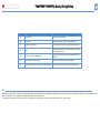
WM40-96 is provided with the “Easy-prog” function which enables a simple, quick, clear and immediate visualization of the instrument measurements, making available only specific variables depend-
ing on the application of the instrument. The available applications are described above.
To leverage all the capacities of the instrument, select the application G which enables a complete and detailed analysis of the electric energy.
5
Selection Application Note
A Cost allocation Imported energy metering
B Cost control Imported and partial energy metering and utilities
C Complex cost allocation Imported/exported energy (total and partial) and utilities
D Solar
Imported and exported energy metering with some basic
power analyzer function
E Complex cost and power analysis
Imported/exported energy (total and partial) and power
analysis
F Cost and power quality analysis Imported energy and power quality analysis
G Advanced energy and power analysis for power generation Complete energy metering and power quality analysis

D
D
I
I
S
S
P
P
L
L
A
A
Y
Y
P
P
A
A
G
G
E
E
S
S
CARLO GAVAZZI
A
utomation Components
6
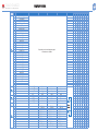
N° Line 1 Line 2 Line 3 Line 4 Line 5 Note
Application
A B C D E F G
0
Total kWh (+)
Depending on the last displayed page of
instantaneous variables.
x x x x x x x
1
Total kvarh (+) x x x x x x
2
Total kWh (-) x x x x
3
Total kvarh (-) x x x
4
kWh (+) partial
x
x x
x
x
5
kvarh (+) part. x x x x x
6
kWh (-) partial x x x
7
kvarh (-) part. x x x
8
Run Hours (99999999.99)
x x x x x
9
kWh (+) t1 x x x
10
kvarh (+) t1 x x x
11
kWh (-) t1 x x x
12
kvarh (-) t1 x x x
13
kWh (+) t2 x x x
14
kvarh (+) t2 x x x
15
kWh (-) t2 x x x
16
kvarh (-) t2 x x x
17
kWh (+) t3 x x x
18
kvarh (+) t3 x x x
19
kWh (-) t3 x x x
20
kvarh (-) t3 x x x
21
kWh (+) t4 x x x
22
kvarh (+) t4 x x x
23
kWh (-) t4 x x x
24
kvarh (-) t4 x x x
25
kWh (+) t5 x x x
26
kvarh (+) t5 x x x
27
kWh (-) t5 x x x
28
kvarh (-) t5 x x x
29
kWh (+) t6 x x x
30
kvarh (+) t6 x x x
31
kWh (-) t6 x x x
32
kvarh (-) t6 x x x
33
C1 x x x x
34
C2 x x x x
35
C3 x x x x
36
Phase seq.
VLN ∑
VL1 VL2 VL3 x x x x
37
Phase seq.
VLL ∑
VL1-2 VL2-3 VL3-1 x x x x
38
Phase seq. An AL1 AL2 AL3 x x x x
39
Phase seq. Hz “ASY” VLL sys (% asy) VLN sys (% asy) x x x x
40
Phase seq.
W ∑
WL1 WL2 WL3 x x x x
41
Phase seq.
var ∑
var L1 var L2 var L3 x x x
42
Phase seq.
PF ∑
PF L1 PF L2 PF L3 x x x
43
Phase seq.
VA ∑
VA L1 VA L2 VA L3 x x x
44
Phase seq. Process sig. Temperature x x
45
Phase seq. THD V1 THD V2 THD V3 x x
46
Phase seq. THD V12 THD V23 THD V31 x x
47
Phase seq. THD A1 THD A2 THD A3 x x
48
Phase seq. THD V1 odd THD V2 odd THD V3 odd x x
49
Phase seq. THD V12 odd THD V23 odd THD V31 odd x x
50
Phase seq. THD A1 odd THD A2 odd THD A3 odd x x
51
Phase seq. THD V1 even THD V2 even THD V3 even x x
52
Phase seq. THD V12 even THD V23 even THD V31 even x x
53
Phase seq. THD A1 even THD A2 even THD A3 even x x
54
Phase seq. TDD A1 TDD A2 TDD A3 x x
55
Phase seq. K-FACT L1 K-FACT L2 K-FACT L3 x x x x

I
I
N
N
F
F
O
O
R
R
M
M
A
A
T
T
I
I
O
O
N
N
P
P
A
A
G
G
E
E
S
S
CARLO GAVAZZI
A
utomation Components
7
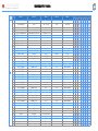
N° Line 1 Line 2 Line 3 Line 4 Line 5
Applications
A B C D E F G
1
Lot n. xxxx Yr. xx rEL X.xx 1...60 (min) “dmd” x x x x x x x
2
Conn. xxx.x (3ph.n/3ph/3ph.1/
3ph.2/1ph/2ph)
CT.rA 1.0 … 99.99k PT.rA 1.0...9999 x x x x x x x
3
LED PULSE kWh xxxx kWh per pulse x x x x x x x
4
PULSE out1 kWh/kvarh xxxx kWh/kvarh per pulse +/- tot/PAr/tAr 1-2-3-4 x x x x x x x
5
PULSE out2 kWh/kvarh xxxx kWh/kvarh per pulse +/- tot/PAr/tAr 1-2-3-4 x x x x x x x
6
PULSE out3 kWh/kvarh xxxx kWh/kvarh per pulse +/- tot/PAr/tAr 1-2-3-4 x x x x x x x
7
PULSE out4 kWh/kvarh xxxx kWh/kvarh per pulse +/- tot/PAr/tAr 1-2-3-4 x x x x x x x
8
PULSE out5 kWh/kvarh xxxx kWh/kvarh per pulse +/- tot/PAr/tAr 1-2-3-4 x x x x x x x
9
PULSE out6 kWh/kvarh xxxx kWh/kvarh per pulse +/- tot/PAr/tAr 1-2-3-4 x x x x x x x
10
PULSE out7 kWh/kvarh xxxx kWh/kvarh per pulse +/- tot/PAr/tAr 1-2-3-4 x x x x x x x
11
PULSE out8 kWh/kvarh xxxx kWh/kvarh per pulse +/- tot/PAr/tAr 1-2-3-4 x x x x x x x
12
Remote output Output 1 on/oFF Output 2 on/oFF x x x x x x x
13
Remote output Output 3 on/oFF Output 4 on/oFF x x x x x x x
14
Remote output Output 5 on/oFF Output 6 on/oFF x x x x x x x
15
Remote output Output 7 on/oFF Output 8 on/oFF x x x x x x x
16
AL1 OUTx NE/ND Variable L 1/2/3 Set 1 Set 2 (Measurement) x x x x
17
AL2 OUTx NE/ND Variable L 1/2/3 Set 1 Set 2 (Measurement) x x x x
18
AL3 OUTx NE/ND Variable L 1/2/3 Set 1 Set 2 (Measurement) x x x x
19
AL4 OUTx NE/ND Variable L 1/2/3 Set 1 Set 2 (Measurement) x x x x
20
AL5 OUTx NE/ND Variable L 1/2/3 Set 1 Set 2 (Measurement) x x x x
21
AL6 OUTx NE/ND Variable L 1/2/3 Set 1 Set 2 (Measurement) x x x x
22
AL7 OUTx NE/ND Variable L 1/2/3 Set 1 Set 2 (Measurement) x x x x
23
AL8 OUTx NE/ND Variable L 1/2/3 Set 1 Set 2 (Measurement) x x x x
24
AL9 OUTx NE/ND Variable L 1/2/3 Set 1 Set 2 (Measurement) x x x x
25
AL10 OUTx NE/ND Variable L 1/2/3 Set 1 Set 2 (Measurement) x x x x
26
AL11 OUTx NE/ND Variable L 1/2/3 Set 1 Set 2 (Measurement) x x x x
27
AL12 OUTx NE/ND Variable L 1/2/3 Set 1 Set 2 (Measurement) x x x x
28
AL13 OUTx NE/ND Variable L 1/2/3 Set 1 Set 2 (Measurement) x x x x
29
AL14 OUTx NE/ND Variable L 1/2/3 Set 1 Set 2 (Measurement) x x x x
30
AL15 OUTx NE/ND Variable L 1/2/3 Set 1 Set 2 (Measurement) x x x x
31
AL16 OUTx NE/ND Variable L 1/2/3 Set 1 Set 2 (Measurement) x x x x
32
Analogue 1 Hi:E 0.0 ... 9999 Hi.A 0.0 ... 100.0% x x x x
33
Analogue 2 Hi:E 0.0 ... 9999 Hi.A 0.0 ... 100.0% x x x x
34
Analogue 3 Hi:E 0.0 ... 9999 Hi.A 0.0 ... 100.0% x x x x
35
Analogue 4 Hi:E 0.0 ... 9999 Hi.A 0.0 ... 100.0% x x x x
36
Optical bdr (text) 9.6/19.2/38.4/115.2 x x x x x x x
37
COM port Add xxx (address) bdr 9.6/19.2/38.4/115.2 x x x x x x x
38
Indirizzo IP XXX XXX XXX XXX x x x x x x x
39
xx.xx.xx xx:xx Date Time x x x x x x x
40
Event, Data, Ora x x x x

P
P
R
R
O
O
G
G
R
R
A
A
M
M
M
M
I
I
N
N
G
G
W
W
M
M
4
4
0
0
-
-
9
9
6
6
Key-pad
NOTE
CARLO GAVAZZI
A
utomation Components
8
P
ush for at
least 2 s
10 CHANGE PAS: this function allows the user to modify the PASS value
with a new value (from 0 to 9999).
20 BACKLIGHT: backlight time from 0 (always on) to 255 minutes.
30 COLOUR: this function allows the user to select the backlight colour
and the working logic. 0: no timer and backlight off. 1: timer and white back-
light. 2: timer and blue backlight. 3: no timer and backlight off, when an alarm
occurs it flashes from white to blue. 4: timer, white backlight, when an alarm
occurs it flashes from white to blue. 5: timer, white backlight, when an alarm
occurs it flashes from blue to white.
40 MODULES: the WM40 96 supports either automatic (A) or manual (M)
acknowledgment of the installed modules depending on the kind of
module.
60 APPLICAT.: this function which enables a simple, quick, clear and
immediate visualization of the instrument measur
ements, making available
only specific variables (page 4/5) depending on the application of the
instrument.
70 SYSTEM: this function allows the user to select the type of
electrical system (see relevant chapter to next page).
80 CT RATIO: this
function allows the user to select the value of the CT ratio (primary/sec-
ondary ratio of the current transformer being used). Example: if the CT pri-
mary (current transformer) has a current of 300A and the secondary a cur-
rent of 5A, the CT ratio corresponds to 60 (obtained using the following
calculation: 300/5.
90 PT RATIO: this function allows to select the value of the VT-PT ratio
(primary/secondary ratio of the voltage transformer being used). Example:
if the primary of the connected VT (voltage transformer/potential trans
-
former) is 20kV and the secondary is 100V, then the VT-PT ratio corre-
sponds to 200 (obtained carrying out the following calculation:
20000/100).
100 CTN RATIO: this function allows to select the value of neutral current AT
ratio (primary/secondary ratio of the used current transformer).
110 DMD: This function allows the user to select the calculation method
of the DMD/AVG value of the selected variable (see the box on page 10).
120 SET POWER: This menu allows you to set a power value (installed power)
that, in the measuring phase, will represent 100% of the graph indicator.
130 HOME PAGE: This function allows the user to select the variables to
be displayed on first page (home page). 131 TYPE: A, you can select the
variable for each row. B, you can select a preset combination of variables
(see relevant chapter to next page). 136 PAGE: select a preset series of
variables (see relevant chapter to next page).
140 FILTER: with the digital filter it’s possible to stabilize the measure-
ments which are too instable when displaying the relevant values. 141 FIL-
TER S: set the operating range (span) of the digital filter
. The value is
expressed as a % (filter to 0.0 means filter excluded). 142 FILTER CO: set
the filtering coefficient of the instantaneous measures. By increasing the
value, also the stability and the settling time of the measur
es ar
e
increased.
Some specific menus display only if the relevant modules are installed.
Measuring
mode
Page 9
See details on
the next page.
PAY ATTENTION
Join or divide the
modules ONLY
when the WM40
is NOT power
supplied.
!

P
P
R
R
O
O
G
G
R
R
A
A
M
M
M
M
I
I
N
N
G
G
W
W
M
M
4
4
0
0
-
-
9
9
6
6
CARLO GAVAZZI
A
utomation Components
9
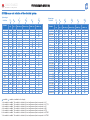
Variable
1-ph.
sys
2-ph.
sys
3-ph. 3/4-wire
balanced sys
3-ph. 2-wire
balanced sys
3-ph. 3-wire
unbal. sys
3-ph. 4-wire
unbal. sys
VL-N sys
VL1
VL2 1 1
VL3 1 1
VL-L sys
VL1-2 2
VL2-3 2
VL3-1 2
AL1
AL2 3 3
AL3 3 3
VA sys
VA L1
VA L2
VA L3
var sys
var L1
var L2
var L3
W sys
WL1
WL2 4 4
WL3 4 4
PF sys
PF L1
PF L2 5 5
PF L3 5 5
Hz
Phase seq.
Variable
1-ph.
sys
2-ph.
sys
3-ph. 3/4-wire
balanced sys
3-ph. 2-wire
balanced sys
3-ph. 3-wire
unbal. sys
3-ph. 4-wire
unbal. sys
Asy VLL
Asy VLN
Run Hours
kWh (+)
kvarh (+)
kWh (+)
kvarh (+)
kWh (-)
kvarh (-)
kWh (-)
kvarh (-)
C1
C2
C3
A L1 THD
A L2 THD 6 6
A L3 THD 6 6
V L1 THD
V L2 THD 7
V L3 THD 7
V L1-2 THD
V L2-3 THD
V L3-1 THD
A L1 TDD
A L2 TDD
A L3 TDD
K-Factor L1
K-Factor L2
K-Factor L3
System type
Selection
1P
2P
3P.1
3P.2
3P
3P.n
System type
Selection
1P
2P
3P.1
3P.2
3P
3P.n
= available; = variable not available on the display
1= the variable is available. The variable is calculated (it is not really measured) and corresponds to VL1
2= the variable is available. The variable is calculated (it is not really measured) and corresponds to VL1*1.73
3= the variable is available. The variable is calculated (it is not really measured) and corresponds to AL1
4= the variable is available. The variable is calculated (it is not really measured) and corresponds to WL1
5= the variable is available. The variable is calculated (it is not really measured) and corresponds to PFL1
6= the variable is available. The variable is calculated (it is not really measured) and corresponds to AL1THD
7= the variable is available. The variable is calculated (it is not really measured) and corresponds to VL1THD
S
S
Y
Y
S
S
T
T
E
E
M
M
m
m
e
e
n
n
u
u
a
a
n
n
d
d
s
s
e
e
l
l
e
e
c
c
t
t
i
i
o
o
n
n
o
o
f
f
t
t
h
h
e
e
e
e
l
l
e
e
c
c
t
t
r
r
i
i
c
c
a
a
l
l
s
s
y
y
s
s
t
t
e
e
m
m

P
P
R
R
O
O
G
G
R
R
A
A
M
M
M
M
I
I
N
N
G
G
W
W
M
M
4
4
0
0
-
-
9
9
6
6
CARLO GAVAZZI
A
utomation Components
10
E
C D
Type Selection 0 1 2 3 4 5 6 7 8 9 10 11
Line
2
Type “a” An
W∑ var∑ VA∑ PF∑
Hz An An An An An An
Type “a” with
System 1P
V A W var VA PF Hz V V V V V
Type “b” Select one of the preset combination of variables
Type “b” with
System
1P
Select one of the preset combination of variables
Line
3
Type “a” An
W∑ var∑ VA∑ PF∑
Hz An An An An An An
Type “a” with
System 1P
V A W var VA PF - - - - - -
Line
4
Type “a”
VL-
L∑
An
W∑ var∑ VA∑ PF∑
Hz - - - - -
Type “a” with
System 1P
V A W var VA PF Hz - - - - -
Line
5
Type “a”
VL-
L
∑
An
W∑ var∑ VA∑ PF∑
Hz - - - - -
Type a with
System 1P
V A W var VA PF Hz - - - - -
E
D
0 1 2 3 4 5 6 7 8 9 10 11 12 13 14 15 16 17 18 19 20
Line
2
-
V
LN ∑
V
LN ∑
An Hz
VA ∑ var ∑ W ∑ PF ∑
- - -
- - - - - - - - -
Line
3
-
V
L1
V
L1-2
A
L1
“ASY”
VA
L1
var
L1
W
L1
PF
L1
THD
V1
THD
V12
THD
A1
THD
V1
even
THD
V12
even
THD
A1
even
THD
V1
odd
THD
V12
odd
THD
A1
odd
k
factor
TDD
A1
Tempe
rature
Line
4
-
V
L2
V
L2-3
A
L2
VLL
sys
(
% asy)
VA
L2
var
L2
W
L2
PF
L2
THD
V2
THD
V23
THD
A2
THD
V2
even
THD
V23
even
THD
A2
even
THD
V2
odd
THD
V23
odd
THD
A2
odd
k
factor
TDD
A2
Proc
Segn
Line
5
-
V
L3
V
L3-1
A
L3
VLL
sys
(
% asy)
VA
L3
var
L3
W
L3
PF
L3
THD
V3
THD
V31
THD
A3
THD
V3
even
THD
V31
even
THD
A3
even
THD
V3
odd
THD
V31
odd
THD
A3
odd
k
factor
TDD
A3
-
E
D
0 1 2 3 4 5 6 7 8 9 10 11 12 13 14 15 16 17 18 19 20
Line
2
Hz W - - -
-
-
-
Line
3
V VAR THD_V
THD_V
even
THD_V
odd
k-Factor TDD A Temperature
Line
4
A VA THD_A
THD_A
even
THD_A
odd
- -
Analogue
signal input
Line
5
- PF - - - - - -
C
D
D
D
D
Line 1
H
H
o
o
w
w
t
t
o
o
c
c
u
u
s
s
t
t
o
o
m
m
i
i
z
z
e
e
t
t
h
h
e
e
h
h
o
o
m
m
e
e
p
p
a
a
g
g
e
e
o
o
f
f
W
W
M
M
4
4
0
0
-
-
9
9
6
6
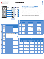
Menu “131 TYPE”:
“a”, you can select a “system” variable for each line.
“b”, you can select a preset combination of variables which is split in line 2 (a system variable) and line 3 to 5
(single phase variables) .
Moreover, the selectable variables depend on the selected electric system, if 1P (one phase) system is select-
ed, the available variables are different.
Note: when the B type is selected all the A selections on line 3, 4 and 5 are irrilevant.
E

P
P
R
R
O
O
G
G
R
R
A
A
M
M
M
M
I
I
N
N
G
G
W
W
M
M
4
4
0
0
-
-
9
9
6
6
CARLO GAVAZZI
A
utomation Components
11
Where:
Pmax is the maximum power,
Pc is the contractual power,
t1 is the selected time period for the calculation of the AVG/DMD value.
FIXED SELECTION: if, for example, a time interval of 15 minutes has been selected, the instrument will cal-
culate the AVG/DMD value of the measured variable and updates its value every 15 minutes.
SLIDING SELECTION: if for example a time interval of 15 minutes has been selected, the instrument calcu-
lates the AVG/DMD value and updates its value at the beginning after the first 15 values and then after every
minute, thus generating a window whose width is of 15 minutes and that moves forward every minute.
SELECTION OF DMD CALCULATION: 111 TYPE: 81 TYPE: select the type of calculation mode to be used for the DMD/AVG calculation FIXED: if, for example, a time interval of 15 minutes has been selected, the instru-
ment will calculate the AVG/DMD value of the measured variable and updates its value every 15 minutes, after that resets and starts a new calculation. SLIDE: if for example a time interval of 15 minutes has been selected, the
instrument calculates the AVG/DMD value and updates its value at the beginning after the first 15 values and then after every minute, thus generating a window whose width is of 15 minutes and that moves forward every minute.
112 TIME: select the time interval for the DMD/AVG calculation 113 SYNC: select the synchronization mode, that is the method that controls the calculation method of the average/demand according to the selected time.

P
P
R
R
O
O
G
G
R
R
A
A
M
M
M
M
I
I
N
N
G
G
W
W
M
M
4
4
0
0
-
-
9
9
6
6
Key-pad
NOTE
CARLO GAVAZZI
A
utomation Components
140 OPTICAL: this function allows the user to set the communication
mode of the front optical port.
150 RS232-485: This function allows the user to set the RS232 and RS485
serial communication ports (MC232485 module).
160 ETHERNET: This function allows the user to set the Ethernet commu-
nication port. In case of BACnet IP port, the BACnet instance number can
only be programmed by WM3040Soft programming software.
170 BACNET 485: This function allows the user to set the BACnet MS/TP
parameters. The BACnet instance number can only be programmed by
WM3040Soft programming software.
180 VIRT AL 1: This function allows you to set the alarm parameters. 181
ENABLE: enable (YES) or disable (NO) the alarm. 182 VARIABLES: set the
variable to be linked to the alarm. 183 SET 1:set the on alarm set point of
the variable. 184 SET 2: set the off alarm set point of the variable. 185 ON
DELAY: set a delay on activation of the alarm.
Some specific menus display only if the relevant modules are
installed.
12
P
ush for at
least 2 s
P
age 7 (110)
Page 12 (350)
L
ist of available
variables
As VIRT AL1
As VIRT
AL1
A
s VIRT
AL1

P
P
R
R
O
O
G
G
R
R
A
A
M
M
M
M
I
I
N
N
G
G
W
W
M
M
4
4
0
0
-
-
9
9
6
6
Key-pad
NOTE
CARLO GAVAZZI
A
utomation Components
350 DIG OUT 1: This function allows to link a virtual alarm to the digital
output and to its working parameters. 351 FUNCTION: Alarm, the digital
output is enabled only if the expected alarm status occurs. Pulse, the
measured energy is retransmitted by the digital output by means of puls-
es.
Remote, the digital output can be enabled through a command sent by
means of serial communication port. 352 AL LINK: select the virtual alarm
to which it has to be linked. 353 AL STATUS: “ND” (normally de-energized
relay) or “NE” (normally energized relay) 355 PULSE WEIG: selects the
pulse weight (kWh per pulse). 356 OUT TEST: enables the TEST (YES), dis-
ables the TEST (NO). 357 POWER TEST: sets the simulated power value
(kW) to which a proportional pulse sequence accor
ding to “PULSE WEIG”
corresponds. The function is active until you remain within the menu and
it is used when the output is connected to a PLC.
440 TARIFF: it allows to select the tarif
fs mode.
450 DIG IN 1: it allows to set the digital inputs parametres. 451 FUNCTION:
function type selection. 452 PULSE TYPE: it allows to set the pulse type.
453 PULSE WEIG: it allows to set the pulse weight.
470 AN OUT 1: this submenu allows the programming of the analogue
outputs (0-20mA, 0-10V). 471 VARIABLES: select the variable to be
retransmitted by means of the analog output. 472 MIN INPUT: minimum
value of the variable input range to which the “MIN OUTPUT” value,
retransmitted by the analogue output, will be linked. 473 MAX INPUT:
maximum value of the variable input range to which the “MAX OUTPUT”
value, retransmitted by the analogue output, will be linked. 474 MIN OUT-
PUT: set the value expressed as % of the output range (0-20mA, 0-10V) to
be linked to the minimum measur
ed value. 475 MAX OUTPUT
: select the
value expressed as % of the output range (0-20mA, 0-10V) to be linked to
the maximum measured value.
520 PROCESS: it allows to set the pr
ocess signal parameters
. 521 UNIT
:
engineering unit selection (°C or °F). 522 PROBE: probe selection. 523
MIN ELECT: selection of electrical scale minimum value. 524 MAX ELECT:
selection of electrical scale maximum value
525 MIN DISPLAY: selection of the displayed minimum value. 526 MAX
DISPLAY: selection of the displayed maximum value.
Some specific menus display only if the relevant modules are
installed.
13
P
ush for at
least 2 s
Page 11 (340)
Page13 (530)
L
ist of available
variables
As AN OUT 4
As DIG OUT 1
As DIG IN 6
List of available variables

Key-pad
NOTE
CARLO GAVAZZI
A
utomation Components
14
P
ush for at
least 2 s
530 METERS: reset the ENERGY METERS choosing among: TOTAL,
PARTIAL: resets all energy meters, both total and partial. TOTAL +: resets
the total meters of imported energy. TOTAL -: resets the total meters of
exported energy. PARTIAL +: resets the partial meters of imported energy.
PARTIAL -: resets the partial meters of exported energy.
TARIFF: tariffs counter reset. HEATING: remote heating counter reset.
TRIP: errors counter reset.
540 RESET: carry out the reset of the MAX or dmd stored values.
550 CLOCK, 551 FORMAT: UE, set the European time format as 24h
(00:00) or the USA set the American time format as 12h (12:00 AM/PM).
P
age 12 (520)
Page 8 (10)
Save the set
parameters and come
back to the measuring
mode.

DIGITAL FILTER PROGRAMMING EXAMPLES
Example 1
How to stabilize the value of the VL-N variable displayed on the dis-
play, fluctuating from 222V and 228V.
The parameters of the digital filter have to be programmed as follows:
FILTER S: the variable has fluctuations within the mean value whose
amplitude is equal to ±0,75% of the full scale rated value of the variable
itself (obtained by the following calculation: (228-222)/ 2= ±3V, then
±3*100/400V= ±0,75% where 400V is the phase-neutral rated value of an
AV5 input). The “range” parameter, representing the action range of the
digital filter, is to be programmed to a value which must be slightly high-
er than the percentage amplitude of the fluctuation: ex. 1.0%.
FILTER CO: if the new value measured by the instrument is within the
action range of the filter, the new displayed value is obtained by adding
algebrically the previous value to the variation divided by the filtering
coefficient. As a consequence, a value higher than this coefficient implies
a longer settling time and therefore a better stability. You generally obtain
the best result by setting the filtering coefficient to a value equal to at
least 10 times the range parameter value.
In the following example: 1,0*10=10, the stability of the filtering coeffi-
cient can be improved by increasing the filtering coefficient, the allowed
values are included within 1 and 255.
Example 2
How to stabilize the value of the displayed System Active Power
(W∑), fluctuating between 300kW and 320kW (the load is connected
to the instrument by means of a 300/5A CT and a direct measure of
the voltage).
The parameters of the digital filter must be programmed as follows:
FILTER S: the variable has fluctuations within the mean value whose
amplitude is equal to ±2,78% of the full scale rated value of this variable.
This value is obtained by the following calculation: (320-300)/ 2= ±10kW,
then ±10*100/360kW= ±2,78%, where 360kW is the rated value of the
System Active Power of an AV5 input, at the above mentioned CT and VT
ratios and obtained by means of the following formula: “VLN * VT * IN *
CT * 3” where VLN = rated input voltage (400V for the AV5 input), VT= pri-
mary/secondary ratio of the voltage transformer being used, IN = rated
current (5A for the AV5 type input), CT = primary/secondary ratio of the
voltage transformer being used (in this example “400*1*5*60*3=360kW).
The RANGE parameter, representing the digital filtering coefficient action
range, is to be programmed to a value which must be slightly higher than
the percentage of the fluctuation: eg. 3.0%.
FILTER CO: if the new value acquired by the instrument is within the fil-
tering action range, the new displayed value is obtained by adding alge-
brically the previous value to the variation divided by the filtering coeffi-
cient. As a consequence, a value higher than this coefficient implies an
higher settling time and therefore a better stability. Generally speaking the
best result is obtained setting the filtering coefficient to a value equal to
at least 10 times the value of the range parameters. In the example:
3.0*10=30. In or
der to impr
ove the stability you can incr
ease the filtering
coefficient, the admitted values are included within 1 and 255.
Example 3.
It’s necessary to stabilize the value of the displayed variable AL 1
(phase current 1), fluctuating within 470V and 486V.
To be able to manage the alarm function and activation and deactivation
of the relay, this value is not to be subject to continuous fluctuations. In
this example we have considered using a 500/5A CT. The parameters of
the digital filter is to be programmed as follows:
FILTER S: the variable has fluctuations within the mean value whose
amplitude is equal to ±1,60% of the full scale rated value of this variable
(obtained by means of the calculation: (486-470)/ 2= ±8A, then
±8*100/500A= ±1,60% where 500A is the value referred to the primary of
the transformer being used). The “range” parameter, which represents the
action range of the digital filter, is to be programmed to a value slightly
higher than the pourcentage amplitude of the fluctuation: for example
2.0%.
FILTER CO: if the new value acquired by the instrument is within the fil-
tering action range, the new displayed value is calculated algebrically
adding to the previous value the variation divided by the filtering coeffi-
cient. As a consequence, a higher value of this coefficient implies a high-
er settling time and therefore a better stability. Generally speaking, the
best result is obtained setting the filtering coefficient at a value equal to
at least 10 times the value of the range parameter. In the example:
2.0*10=20. To improve the stability you can increase the filtering coeffi-
cient, the admitted values are within 1 and 255.
P
P
R
R
O
O
G
G
R
R
A
A
M
M
M
M
I
I
N
N
G
G
W
W
M
M
4
4
0
0
-
-
9
9
6
6
CARLO GAVAZZI
Automation Components
15
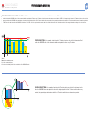
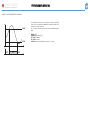
WHAT IS THE ACTION OF THE DIGITAL FILTER PARAMETERS ON THE MEASURE?
The first filter parameter is FILTER S and defines the operating range of the filter. This operating range is represented as a yellow band
in figure on left side (each small square is one digit). Until the measured value (red curve in figure) is within this band, the filter is active;
as soon as the value is external, the filter is deactivated and a new band will be active around the new value.
The range of the fluctuation (in digit) is a good starting value for such parameters.
The suggestion to set this parameter is to look at the size of the fluctuation (in digit) and use this value.
The second parameter is
FILTER CO and represents the filtering coefficient. The higher is FILTER CO, the smoother is the curve of the
displayed values (black in figure). There is not a theoretical rule to define this parameter, it is to be set on the field: however a rough
suggestion is to start with the same value of the
FILTER S coefficient and then increase it until the desired stability is reached.
The digital filter affects the values retransmitted both via serial communication and analogue output.
No filter action
Digital fluctuation

PROGRAMMING EXAMPLES OF THE ANALOGUE OUTPUTS
Power retransmission by means of a 0-20mA analogue output.
It’s necessary to measure a consumed power up to 100kW and retrans-
mit this value by means of a signal from 4 to 20 mA: the module to be
used is MOV2 (2x from 0 to 20mA), the instrument is to be programmed
as follows:
VARIABLE: W∑ (system active power).
MIN OUT: 20.0% means 4 mA. The calculation to be carried out is the fol-
lowing: (100*minimum output) / fullscale output =100*4mA/ 20mA=20%.
MAX OUT: 100.0% means 20mA. The calculation to be carried out is:
(100*maximum output) / fullscale output = 100*20mA/20mA= 100.
MIN INPUT: 0,0k; the multiple k,M,G can be selected on the instrument
according to the chosen VT and CT values.
MAX INPUT: 100.0k; the k, M, G multiples can be selected on the instru-
ment according to the selected VT and CT values.
Retransmission of the POWER FACTOR (PF) by means of the
0-20mA analog output.
It’s necessary to retransmit the whole range of the allowed values for the
PF with a signal from 0 to 20mA. Particular attention must be paid to the
value of the PF variable which may vary from C0,001 and L0,000 (for each
phase): these values will be retransmitted and will then correspond to 0
and 20 mA. When the PF will have a value equal to 1, being in the mid-
dle between C0,001 and L0,000, the value of the output will correspond
to the middle of the scale, that is 10mA. As a consequence, the instru-
ment will have to be programmed as follows:
VARIABLE: PF L1 (or L2 or L3 or PF∑).
MIN OUT: 0,0%.
MAX OUT: 100,0%.
MIN INPUT: C0,001 (the C symbol shows a CAPACITIVE value).
MAX INPUT: L0,001 (the L symbol shows an INDUCTIVE value). L0,001
has been chosen as minimum value to be set in order to avoid any unde-
sirable swifting of the repeated outputs.
P
P
R
R
O
O
G
G
R
R
A
A
M
M
M
M
I
I
N
N
G
G
W
W
M
M
4
4
0
0
-
-
9
9
6
6
CARLO GAVAZZI
Automation Components
16

P
P
R
R
O
O
G
G
R
R
A
A
M
M
M
M
I
I
N
N
G
G
W
W
M
M
4
4
0
0
-
-
9
9
6
6
CARLO GAVAZZI
A
utomation Components
17
EXAMPLE OF ALARM PARAMETERS PROGRAMMING
It is required the disconnection of a load when a set value of absorbed
power occurs. For example when 300kW are exceeded, the alarm occurs
and the set load is disconnected.
An “UP” alarm is selected, below you’ll find the recommended program-
ming:
ENABLE: YES
VARIABLES: W system (W∑)
SET POINT 1: 300kW
SET POINT 2: 295kW
ON DELAY: set the desired number of seconds: “5 seconds”.
300kW
295kW

www.gavazzi-automation.com

W
M
4
0
9
6
CARLO GAVAZZI
A
u t o m a t i o n C o m p o n e n t s
Carlo Gavazzi Controls SpA,
V
ia Safforze, 8 - 32100
B
elluno (Italy)
Tel. +39 0437 355811,
F
ax +39 0437 355880
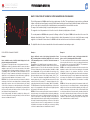
Read carefully the instruction manual. If the instrument is used in a
manner not specified by the producer, the protection provided by the
instrument may be impaired. Maintenance: make sure that the con-
nections are correctly carried out in order to avoid any malfunctioning
or damage to the instrument. To keep the instrument clean, use a slightly damp
cloth; do not use any abrasives or solvents. We recommend to disconnect the
instrument before cleaning it.
WARNING: to make sure that the screw tightening torque is 0.5Nm. ALL THE
MOUNTING AND DISASSEMBLY OPERATIONS OF THE INSTRUMENT AND
MODULES HAVE TO OCCUR WHEN POWER SUPPLY AND THE LOADS ARE
NOT CONNECTED.
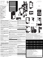
Preliminary operations: if necessary remove the protection cover of the contacts
[A], using a properly screwdriver.
Lock the programming and LED of power supply on: to lock the acces to the
programming of the instrument turning (clockwise) the rotary switch [B] to position
7. To unlock the programming come-back the rotary switch to the position 1. The
green LED [C] on warns that the instrument is power supplayed.
The instrument and modules sealing: to lock the modules turning (clockwise) the
properly fixing elements on the corners [E], using a properly screwdriver [F]. To seal
the instrument use the dedicated covers and holes [D]. Bracket tightening torque:
0,4 Nm max [G].
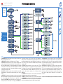
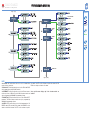
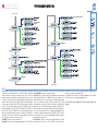
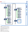
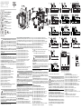
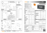
n WIRING DIAGRAMS
[1] 3-ph, 2-wire, balanced load, 1-CT connection.
[2] 3-ph, 2-wire, balanced load, 1-CT and 1-VT/PT connections
[3] 3-ph, 4-wire, unbalanced load, 3-CT connection
[4] 3-ph, 4-wire, unbalanced load, 3-CT and 3-VT/PT connections
[5] 3-ph, 3-wire, unbalanced load, 3-CT connection
[6] 3-ph, 3-wire unbalanced load, 3-CT and 2-VT/PT connections
[7] 3-ph, 3-wire, balanced load, 1-CT connections
[8] 3-ph, 3-wire, unbalanced load, 2-CT connections (ARON)
[9] 3-ph, 3-wire, balanced load, 1-CT and 2-VT/PT connections
[10] 2-ph, 3-wire, 2-CT connection
[11] 2-ph, 3-wire, 2-CT and 2-VT/PT connections
[12] 1-ph, 2-wire, 1-CT connection
[13] 1-ph, 2-wire, 1-CT and 1-VT connections
[14] 3-ph, 3-wire, unbalanced load, 2-CT and 2-VT/PT connections ARON
[15] Power supply 90 to 260VAC/DC. F=250V [T] 630mA.
Power supply 18 to 60VAC/DC. F=250V [T] 3.15A.
Leggere attentamente il manuale di istruzioni. Qualora l’apparec-
chio venisse adoperato in un modo non specificato dal costruttore, la
protezione prevista dall’apparecchio potrebbe essere compromessa.
Manutenzione: Per mantenere pulito lo strumento usare un panno
inumidito; non usare abrasivi o solventi. Si consiglia di scollegare lo strumento
prima di eseguire la pulizia.
ATTENZIONE: assicurarsi che la coppia di serragio applicata alle viti dei morsetti
sia di: 0,5Nm. TUTTE LE OPERAZIONI DI MONTAGGIO E SMONTAGGIO
DELLO STRUMENTO E DEI MODULI VANNO ESEGUITE CON ALIMENTAZIO-
NE E CARICO SCOLLEGATI.
Operazione preliminare: smontare, se necessario, la finestra di protezione dei
contatti [A], utilizzando un apposito cacciavite a taglio.
ITALIANO
ENGLISH
Alimentation de 18 à 60VCA/CC. F=250V [T] 3.15A.
Lea atentamente el manual de instrucciones. Si el instrumento se
usa de modo distinto al indicado por el fabricante, la protección de
seguridad ofrecida por el instrumento podrá resultar dañada.
Mantenimiento: para limpiar el equipo utilizar siempre un trapo lige-
ramente humedecido, nunca productos abrasivos o disolventes. Se recomienda
desconectar siempre el instrumento antes de limpiarlo.
ATENCIÓN: asegúrese de que el par de apriete aplicado a los tornillos sea de:
0,5Nm. TODAS LAS OPERACIONES DE MONTAJE Y DESMONTAJE DEL
INSTRUMENTO Y DE LOS MÓDULOS DEBE REALIZARSE CON LA
ALIMENTACIÓN Y LA CARGA DESCONECTADAS.
Operación preliminar: desmonte, si lo necesita, la ventana de protección de los
contactos [A], utilizando su propio destornillador de punta plana.
Bloqueo de la programación y LED de alimentación ON: para bloquear la pro-
gramación del instrumento gire en el sentido de las agujas del reloj el conmutador
giratorio [B] llevándolo a la posición 7, para desbloquear la programación llévelo a
la posición 1. El LED verde encendido [C] indica que el instrumento está alimenta-
do.
Sellado de los módulos y del instrumento: para bloquear los módulos gire en el
sentido de las agujas del reloj los específicos elementos de fijación de los extremos
de los módulos [E], utilizando un adecuado destornillador de punta plana [F]. Para
sellar el equipo use las cubiertas y orificios específicos [D]. Par de apriete del sopor-
te: 0,4 Nm máx [G].
ESPAÑOL
n CONEXIONES ELÉCTRICAS
[1] Trifásico, 2 hilos, carga equilibrada, conexión mediante 1 CT
[2] Trifásico, 2 hilos, carga equilibrada, conexión mediante 1 CT y 1 VT/PT
[3] Trifásico, 4 hilos, carga desequilibrada, conexión mediante 3 CT
[4] Trifásico, 4 hilos, carga desequilibrada, conexión mediante 3 CT y 3 VT/PT
[5] Trifásico, 3 hilos, carga desequilibrada, conexión mediante 3 CT
[6] Trifásico, 3 hilos, carga desequilibrada, conexión mediante 3 CT y 2 VT/PT
[7] Trifásico, 3 hilos, carga equilibrada, conexión mediante 1 CT
[8] Trifásico, 3 hilos, carga desequilibrada, conexión mediante 2 CT (ARON)
[9] Trifásico, 3 hilos, carga equilibrada, conexión mediante 1 CT y 2 VT/PT
[10] Bifásico, 3 hilos, conexiones mediante 2 CT
[11] Bifásico, 3 hilos, conexiones mediante 2 CT y 2 VT/PT
[12] Monofásico, 2 hilos, conexión mediante 1 CT
[13] Monofásico, 2 hilos, conexión mediante 1 CT y 1 VT/PT
[14] Trifásico, 3 hilos, carga desequilibrada, conexión mediante 2 CT y 2 VT/PT
(ARON)
[15] Alimentación de 90 a 260VCA/CC. F=250V [T] 630mA.
Alimentación de 18 a 60VCA/CC. F=250V [T] 3.15A.
CT = Trafo de intensidad, VT = Trafo de tensión, PT = Trafo de potencia
[5] 3 Phasen, 3 Adern, unsymmetrische Last, Anschluss mit 3 TA
[6] 3 Phasen, 3 Adern, unsymmetrische Last, Anschluss mit 3 TA und 2 TV
[7] 3 Phasen, 3 Adern, symmetrische Last, Anschluss mit 1 TA
[8] 3 Phasen, 3 Adern, unsymmetrische Last, Anschluss mit 2 TV (ARON)
[9] 3 Phasen, 3 Adern, symmetrische Last, Anschluss mit 1 TA und 2 TV
[10] 2 Phasen, 3 Adern, Anschlüsse mit 2 TA
[11] 2 Phasen, 3 Adern, Anschlüsse mit 2 TA und 2 VT
[12] 1 Phase, 2 Adern, Anschluss mit 1 TA
[13] 1 Phase, 2 Adern, Anschluss mit 1 TA und 1 TV
[14] 3 Phasen, 3 Adern, unsymmetrische Last, Anschluss mit 2 TA und 2 TV
(ARON)
[15] Stromversorgung von 90 bis 260 VAC/DC. F=250V [T] 630mA.
Stromversorgung von 18 bis 60 VAC/DC. F=250V [T] 3.15A.
Lire attentivement le manuel de l’utilisateur. Si l’appareil est utilisé
dans des conditions différentes de celles spécifiées par le fabricant, le
niveau de protection prévu par l’instrument peut être compromis.
Entretien: Pour nettoyer l’instrument, utiliser un chiffon humide; ne
pas utiliser d’abrasifs ou de solvants. Il faut déconnecter le dispositif avant de pro-
céder au nettoyage.
ATTENTION: s’assurer que le couple de serrage appliqué aux vis des bornes soit
de: 0,5Nm. POUR TOUTES LES OPÉRATIONS DE MONTAGE ET DÉMONTAGE
DE L’INSTRUMENT ET DES MODULES IL FAUT QUE L’ALIMENTATION ET LA
CHARGE SOIENT DÉBRANCHÉES.
Opération préliminaire: démonter, si nécessaire, la fenêtre de protection des con-
tacts [A], en utilisant un tournevis plat approprié.
Blocage de la programmation et LED pour la présence d’alimentation: pour
bloquer la programmation de l’instrument, agir (en le tournant dans le sens des
aiguilles d’une montre) sur le commutateur rotatif [B] en le mettant sur la position
7, pour débloquer la programmation, le mettre sur la position 1. Le LED vert allumé
[C] signale que l’instrument est alimenté.
Sceller les modules et l’instrument: pour bloquer les modules, agir (en les tour-
nant dans le sens des aiguilles d’une montre) sur les éléments de fixation prévus à
cet effet, situés aux angles des modules mêmes [E], en utilisant un tournevis plat
adéquat [F]. Le sceau doit être posé en utilisant les trous et les couvre-bornes pré-
vus pour à cet effet [D]. Couple de serrage des vis de l'étrier de maintien: 0,4 Nm
max [G].
n BRANCHEMENTS ÉLECTRIQUES
[1] 3 phases, 2 fils, charge équilibrée, connexion avec 1 TA
[2] 3 phases, 2 fils, charge équilibrée, connexion avec 1TA et 1 TV
[3] 3 phases, 4 fils, charge déséquilibrée, connexion avec 3 TA
[4] 3 phases, 4 fils, charge déséquilibrée, connexion avec 3 TA et 3 TV
[5] 3 phases, 3 fils, charge déséquilibrée, connexion avec 3 TA
[6] 3 phases, 3 fils, charge déséquilibrée, connexion avec 3 TA et 2 TV
[7] 3 phases, 3 fils, charge équilibrée, connexion avec 1 TA
[8] 3 phases, 3 fils, charge déséquilibrée, connexion avec 2 TV (ARON)
[9] 3 phases, 3 fils, charge équilibrée, connexion avec 1 TA et 2 TV
[10] 2 phases, 3 fils, connexions avec 2 TA
[11] 2 phases, 3 fils, connexions avec 2 TA et 2 VT
[12] 1 phase, 2 fils, connexion avec 1TA
[13] 1 phase, 2 fils, connexion avec 1 TA et 1 TV
[14] 3 phases, 3 fils, charge déséquilibrée, connexion avec 2 TA et 2 TV (ARON)
[15] Alimentation de 90 à 260VCA/CC. F=250V [T] 630mA.
FRANÇAIS
Blocco della programmazione e LED di presenza alimentazione: per bloccare
la programmazione dello strumento agire (ruotandolo in senso orario) sul commu-
tatore rotante [B] portandolo nella posizione 7, per sbloccare la programmazione
portarlo nella posizione 1. Il LED verde acceso [C] avvisa che lo strumento è ali-
mentato.
Sigillatura dei moduli e dello strumento: per bloccare i moduli agire (ruotandoli
in senso orario) sugli appositi elementi di fissagio posti agli angoli dei moduli stessi
[E], utilizzando un adeguato cacciavite a taglio [F]. Il sigillo va apposto utilizzando i
fori e i copri morsetti dedicati [D]. Coppia di serraggio delle staffe: 0,4 Nm max [G].
n COLLEGAMENTI ELETTRICI
[1] 3 fasi, 2 fili, carico equilibrato, connessione con 1 TA
[2] 3 fasi, 2 fili, carico equilibrato, connessione con 1TA e 1 TV
[3] 3 fasi, 4 fili, carico squilibrato, connessione con 3 TA
[4] 3 fasi, 4 fili, carico squilibrato, connessione con 3 TA e 3 TV
[5] 3 fasi, 3 fili, carico squilibrato, connessione con 3 TA
[6] 3 fasi, 3 fili, carico squilibrato, connessione con 3 TA e 2 TV
[7] 3 fasi, 3 fili, carico equilibrato, connessione con 1 TA
[8] 3 fasi, 3 fili, carico squilibrato, connessione con 2 TV (ARON)
[9] 3 fasi, 3 fili, carico equilibrato, connessione con 1 TA e 2 TV
[10] 2 fasi, 3 fili, connessioni con 2 TA
[11] 2 fasi, 3 fili, connessioni con 2 TA e 2 VT
[12] 1 fase, 2 fili, connessione con 1TA
[13] 1 fase, 2 fili, connessione con 1 TA e 1 TV
[14] 3 fasi, 3 fili, carico squilibrato, connessione con 2 TA e 2 TV (ARON)
[15] Alimentazione da 90 a 260VCA/CC. F=250V [T] 630mA.
Alimentazione da 18 a 60VCA/CC. F=250V [T] 3.15A.
Die Betriebsanleitung aufmerksam lesen. Sollte das Gerät nicht
gemäss der Herstellerangaben verwendet werden, könnte der vom
Gerät vorgesehene Schutz beeinträchtigt werden. Wartung: Das
Gerät mit einem feuchten Tuch reinigen; keine Scheuer- oder
Lösemittel verwenden. Das Gerät vor der Reinigung ausschalten
ACHTUNG: Darauf achten, dass das Anzugsmoment der Klemmenschrauben
0,5Nm beträgt. SOWOHL BEI DER MONTAGE, ALS AUCH BEIM AUSBAU DES
GERÄTES UND DER MODULE MÜSSEN STROMVERSORGUNG UND
STROMLAST STETS VORHER ABGETRENNT WERDEN.
Vorbereitung: Gegebenenfalls das Schutzfenster der Kontakte [A] mit einem
Schlitzschraubenzieher entfernen.
Programmierungssperre und LED Stromversorgung vorhanden: Um die
Programmierung des Gerätes zu sperren, den Drehschalter [B] im Uhrzeigersinn
auf Position 7 drehen, für die erneute Freigabe auf Position 1. Das Leuchten der
grünen LED [C] zeigt an, dass das Gerät mit Strom versorgt wird.
Versiegelung der Module und des Geräts: Die Befestigung der Module erfolgt
(durch Drehen derselben im Uhrzeigersinn) über die an den Ecken vorgesehenen
Befestigungselemente [E], mit Hilfe eines passenden Schlitzschraubenziehers [F].
Das Siegel wird über die hierfür vorgesehenen Löcher und Klemmendeckel [D]
angebracht. Befestigungsbügel Anzugsmoment: max 0,4 Nm [G].
n ELEKTRISCHE ANSCHLÜSSE
[1] 3 Phasen, 2 Adern, symmetrische Last, Anschluss mit 1 TA
[2] 3 Phasen, 2 Adern, symmetrische Last, Anschluss mit 1 TA und 1 TV
[3] 3 Phasen, 4 Adern, unsymmetrische Last, Anschluss mit 3 TA
[4] 3 Phasen, 4 Adern, unsymmetrische Last, Anschluss mit 3 TA und 3 TV
DEUTSCH
W
M4096 IM ML 241014 BASE cod
.
8021429
[B]
[C]
[D]
[D]
Instruction Manual
Base Instrument
[F]
[A]
[D]
[E]
[E]
[D]
Thank you
for choosing our products.
Grazie
per aver scelto i nostri prodotti.
Wir danken
Ihnen dafür, dass Sie unsere
Produkte gewählt haben.
Gracias
por elegir nuestros productos.
Merci
d’avoir choisi nos produits.
LED
[G]
L1 N S1 S2
I1
L1 N S1 S2
I
1
L1 L2 L3 N S1 S2 S1 S2 S1 S2
I
1 I2 I3
L
1 L2 L3 N S1 S2 S1 S2 S1 S2
I1 I2 I3
L1 L2 L3 S1 S2 S1 S2 S1 S2
I1 I2 I3
L
1 L2 L3 S1 S2 S1 S2 S1 S2
I1 I2 I3
L1 L2 L3 S1 S2 S1 S2 S1 S2
I1 I2 I3
L1 L2 L3 S1 S2 S1 S2 S1 S2
I1 I2 I3
L1 L2 L3 S1 S2
I1
L1 L2 L3 S1 S2
I1
L1 L2 N S1 S2 S1 S2
I
1 I2
L1 L2 N S1 S2 S1 S2
I1 I2
L1 N S1 S2
I
1
L1 N S1 S2
I1
1
2
+
-
[1]
[2]
[3]
[4]
[5]
[6]
[7]
[8]
[9]
[10]
[11]
[12]
[13]
[14]
[15]
Seite laden ...
Seite laden ...
Seite laden ...
Seite laden ...
Seite laden ...
-
 1
1
-
 2
2
-
 3
3
-
 4
4
-
 5
5
-
 6
6
-
 7
7
-
 8
8
-
 9
9
-
 10
10
-
 11
11
-
 12
12
-
 13
13
-
 14
14
-
 15
15
-
 16
16
-
 17
17
-
 18
18
-
 19
19
-
 20
20
-
 21
21
-
 22
22
-
 23
23
-
 24
24
-
 25
25


CARLO GAVAZZI WM4096 Benutzerhandbuch
- Kategorie
- Komfortbeleuchtung
- Typ
- Benutzerhandbuch
in anderen Sprachen
- English: CARLO GAVAZZI WM4096 User manual
- français: CARLO GAVAZZI WM4096 Manuel utilisateur
- español: CARLO GAVAZZI WM4096 Manual de usuario
- italiano: CARLO GAVAZZI WM4096 Manuale utente
Verwandte Papiere
-
CARLO GAVAZZI WM3096 Benutzerhandbuch
-
-
CARLO GAVAZZI EM2696AV53HI3S1XX Installationsanleitung
-
-
-
-
-
-
-
Sonstige Unterlagen
-
Gossen MetraWatt U180A Bedienungsanleitung
-
Hager HTG410H Bedienungsanleitung
-
HANYOUNG NUX Foot Switch Bedienungsanleitung
-
CAME 67400011 Installationsanleitung
-
Airzone Aidoo Pro Benutzerhandbuch
-
 Lauda Proline Accessories Bedienungsanleitung
-
 Ditel IDEAL-P Quick Start
-
Amprobe ACD-50 Series Benutzerhandbuch
-
 Ditel NMA-NMV Quick Start
-


