Lauda Proline Accessories Bedienungsanleitung
- Typ
- Bedienungsanleitung

Proline Modules
LAUDA DR. R. WOBSER
GMBH & CO. KG
P.O.Box 1251
Germany
97912 Lauda-Königshofen
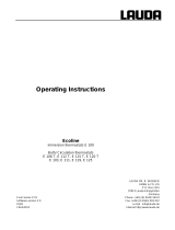
from serial: B 01
from Software version 1.0
YAAE0019
Phone: +49 (0)9343/ 503-0
Fax: +49 (0)9343/ 503-222
e-mail info@lauda.de
Internet http://www.lauda.de
Operating Instruction
PROLINE
Interface Modules


Proline Modules
YAAE0019/ 08.01.04 Contents 3
Contents
1 SAFETY INFORMATION......................................................................................................................................4
1.1 GENERAL SAFETY INFORMATION .........................................................................................................................4
1.2 OTHER SAFETY INFORMATION .............................................................................................................................4
2 INSTALLING MODULES......................................................................................................................................5
3 MENU STRUCTURE FOR ALL MODULES (ONLY COMMAND)....................................................................6
4 SERIAL INTERFACES RS232 / 485......................................................................................................................7
4.1 MENU STRUCTURE FOR RS232 / 485 INTERFACE MODULE (MASTER)...................................................................7
4.2 RS 232 INTERFACE.............................................................................................................................................8
4.2.1 Connecting cables and interface test RS 232 ...............................................................................................8
4.2.2 Protocol RS 232..........................................................................................................................................8
4.3 RS 485 INTERFACE.............................................................................................................................................9
4.3.1 Connecting cable RS 485............................................................................................................................9
4.3.2 Protocol RS 485..........................................................................................................................................9
4.4 WRITE COMMANDS (DATA COMMANDS TO THE THERMOSTAT)............................................................................10
4.5 READ COMMANDS (DATA REQUESTED FROM THE THERMOSTAT).........................................................................11
4.6 ERROR MESSAGES.............................................................................................................................................13
4.7 DRIVER SOFTWARE FOR LABVIEW® ...............................................................................................................13
5 ANALOGUE MODULE........................................................................................................................................14
5.1 MENU STRUCTURE ANALOGUE MODULE (MASTER)............................................................................................15
6 CONTACT MODULE...........................................................................................................................................16
6.1 CONTACT MODULE LRZ 915 WITH THREE INPUTS AND THREE OUTPUTS..............................................................16
6.2 NAMUR-CONTACT MODULE LRZ 914 WITH ONLY ONE INPUT AND ONE OUTPUT ..................................................17
6.3 MENU STRUCTURE CONTACT MODULE (MASTER)...............................................................................................18
7 INDEX....................................................................................................................................................................19
Explanation of signs:
Danger: This sign is used where there may be injury to person-
nel if a recommendation is not followed accurately dis-
regarded.
☞ Note: Here special attention is drawn to some aspect. May
include reference to danger.
¿
Reference: Refers to other information in different Sections.

Proline Modules
4 Safety information YAAE0019 / 08.01.04
1 Safety information
1.1 General safety information
A laboratory thermostat heats and circulates liquids according to specified parameters. This involves
hazards due to high temperatures, fire and general hazards due to the application of electrical energy.
The user is extensively protected by the application of relevant standards.
Other sources of hazardsmay arise due to the type of tempering medium, e.g. by exceeding or under-
cutting certain temperature thresholds or with the breakage of the container and reaction with the tem-
pering liquid.
It is not possible to consider all eventualities. They remain largely subject to the judgment and responsi-
bility of the operator.
The equipment may only be used as prescribed and as described in these operating instructions. This
includes operation by instructed specialist personnel.
The equipment fulfils the following classes of the EMC standard EN 61326-1:
Class A: Operation only on networks without connected domestic areas.
Class B: Equipment for operation on networks with connected domestic areas.
Class B*: Equipment fulfils Class B when a house connection > 100 A is involved. With unfavourable
network conditions disturbing voltage variations may otherwise occur.
The equipment is not rated for use under medical conditions according to EN 60601-1 or IEC 601-1.
1.2 Other safety information
Follow the operating instructions for the thermostat.
Only connect equipment to PE grounded mains sockets.
Withdraw the mains plug before cleaning, maintenance or moving the thermostat.
Repairs in the control section must only be carried out by specialist personnel!
Figures of temperature constancy and display accuracy apply under normal conditions according to DIN
12876. Electromagnetic high frequency fields may in special cases lead to unfavorable values. Safety is
not impaired.

Proline Modules
YAAE0019/ 08.01.04 Installing modules 5
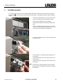
2 Installing modules
The master and command can be supplemented with further interface modules which are simply in-
serted at the back of the control head into two module slots ( operating manual for the Proline ther-
mostat).
− Touch the earthed bath cover of the Proline ther-
mostat to discharge any electrostatic charge.
− Remove the module from its packaging
− Switch off the thermostat and pull out the mains
plug.
− Insert a screwdriver into the lower recess of the
module cavity and prise up the plastic cover. The
cover can then be pulled off downwards.
− Pull out the plug of the bus connecting cable from
the plastic cover.
− Plug on the bus connecting cable (red plug onto
red socket).
− Insert the module and secure with the two cross-
head screws.
− Connect the mains plug again and switch on the
thermostat.
☞ The plugs are protected against reverse polarity.
The plugs have a ridge which slides into a groove
in the socket.

Proline Modules
6 Menu structure for all modules (only Command) YAAE0019 / 08.01.04
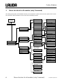
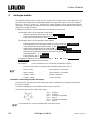
3 Menu structure for all modules (only Command)
All existing menu points are illustrated. However, the Command Console masks out menu points which cannot
be executed. Further information can be found in the following sections.
Input 1
Input 2
Input 3
Output 1
Output 1
Output 1
Menu
Modules
Status
Function
Interface type
Minimum value
Maximum value
Calibration
Analogue Input 1
Analogue Input 2
Analogue Output 1
Analogue Output 2
Setpoint temperature
Ext. actual temp.
Pump power
Serial
Analogue interfaces
Switching contacts
RS232
RS485
Off
On
Setpoint temperature
Controlled temp.
Internal temp.
Temp.extern Pt100
Temp.extern analog
Temp.extern serial
Actuating signal
Pump power
Pump speed
2400
4800
9600
19200
Mode
Baud rate
RS485 address
Voltage 0-10V
Current 0-20mA
Current 4-20mA
Status
Function
Interface type
Minimum value
Maximum value
Calibration
Off
On
Voltage 0-10V
Current 0-20mA
Current 4-20mA
Function
Contact open
Contact closed
Off
Fault
Stand-by
Programmer
Alternating mode
Control type
Only if setpoint
temp. alternating
mode is active:
Input open-Temp.
Input closed-Temp.
Only if
control type is active:
Internal Pt100
External Pt100
External analogue
External serial
Off
Fault diagnosis
Stand-by
Temperature range
Programmer
Refill
Function
Diagnostic function
Temperature range
Only if fault diagno-
sis is active:
All messages
Low level
Overtemperature
Only fault
Only if temperature
range is active:
Input of range

Proline Modules
YAAE0019 / 08.01.04 Serial interfaces RS232 / 485 7
4 Serial interfaces RS232 / 485
RS232 / 485 Interface Module (order no. LRZ 913) with 9-pole SUB-D socket. Electrically isolated by
optocoupler. With the LAUDA instruction set essentially compatible to the Ecoline and Integra Series.
The RS232 interface can be connected directly to the PC with a 1:1 through-contact cable (order no.
EKS 037).
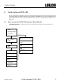
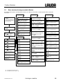
4.1 Menu structure for RS232 / 485 Interface Module (Master)
All existing menu points are illustrated. However, the Master unit masks out menu points which
cannot be executed.
Actual bath temperature
or actual value of exter-
nal temperature
Configure
modules
Display level
Select RS485
address
Select baud rate
Select RS232 or
485
Restore
factory settings
Quit menu
Configure serial
module
: Display module software
version
: Display 24V supply
voltage
: Module serial number
Places 1-5
Quit calibration level
: Module serial number
Places 6-10

Proline Modules
8 Serial interfaces RS232 / 485 YAAE0019 / 08.01.04
4.2 RS 232 Interface
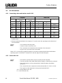
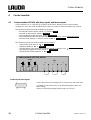
4.2.1 Connecting cables and interface test RS 232
Computer Thermostat
Signal 9-pin sub-D-
socket 25-pin sub-D-
socket 9-pin sub-D-socket Signal
① ② ① ② ① ②
R x D 2 2 3 3 2 2 T x D
T x D 3 3 2 2 3 3 R x D
DTR 4 20 4 DSR
Signal
Ground 5 5 7 7 5 5 Signal Ground
DSR 6 6 6 DTR
RTS 7 4 7 CTS
CTS 8 5 8 RTS
① with hardware handshake: For connecting a thermostat to the PC use 1:1 cable and not a null-
modem cable!
② without hardware handshake: the computer / PC must be set to the operating mode “without hard
ware handshake”.
☞
− Use screened connecting cable..
− Connect screen to connector case.
− The connections are isolated from the remainder of the electronics.
− Any pins not in use must not be connected!!
When a PC is connected up the RS232 interface can easily be tested using the Microsoft Windows
operating system. On Windows® 95/ 98/ NT/ XP with the „Hyper Terminal” program.
4.2.2 Protocol RS 232
☞
− The interface operates with 1 stop bit, no parity bit and 8 data bits..
− Transfer rate either 2400, 4800, 9600 (factory setting) or 19200 baud as selected..
− The RS232 interface can be operated with or without hardware handshake,
(RTS/CTS).
− The command from the computer must be terminated with CR, CRLF, or LFCR.
− The response of the thermostat is always terminated with CRLF.
CR = Carriage Return (Hex: 0D)
LF = Line Feed (Hex: 0A)

Proline Modules
YAAE0019 / 08.01.04 Serial interfaces RS232 / 485 9
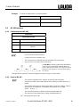
Example: Transfer of setpoint 30,5°C to the thermostat
Rechner Thermostat
„OUT_SP_00_30.5“CRLF
„OK“CRLF
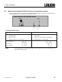
4.3 RS 485 Interface
4.3.1 Connecting cable RS 485
Thermostat
9-pin sub-D-socket
Pin Data
1 Data A
5 SG (Signal Ground)
optional
6 Data B
☞
− Use screened connecting cables.
− Connect screen to connector case.
− The connections are isolated from the remainder of the electronics.
− Any pins not in use must not be connected!!
An RS 485 bus always requires bus termination
in the form of a termination network which en-
sures a defined rest status in the high-resistance
phases of bus operation. The bus termination is
as follows:
This termination network is usually incorporated on the PC plug-in card (RS 485).
4.3.2 Protocol RS 485
☞
− The interface operates with 1 stop bit, no parity bit and 8 data bits.
− Transfer rate either 2400, 4800, 9600 (Factory setting) or 19200 baud as se-
lected.
− The RS 485 commands are always preceded by the device address. There is
provision for 127 addresses. The address must always have 3 digits.
(A000_...to A127_...)
− The command from the computer must be terminated with CR.
− The response of the thermostat is always terminated with CR.
CR = Carriage Return (Hex: 0D)

Proline Modules
10 Serial interfaces RS232 / 485 YAAE0019 / 08.01.04
Example: Transfer of setpoint 30.5°C to the thermostat with address 15.
Computer Thermostat
„A015_OUT_SP_00_30.5“CR
„A015_OK“CR
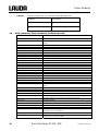
4.4 Write commands (Data commands to the thermostat)
Command Explanation
OUT_PV_05_XXX.XX Externe Temperatur über Schnittstelle vorgeben
OUT_SP_00_XXX.XX Sollwertübergabe mit max. 3 Stellen vor dem Dezimalpunkt und max. 2 Stellen
danach
OUT_SP_01_XXX Pumpenleistungsstufe 1 bis 8
OUT_SP_04_XXX TiH outflow temperature high limit
OUT_SP_05_XXX TiL outflow temperature low limit
OUT_PAR_00_XXX.X Setting of control parameter Xp
OUT_PAR_01_XXX Setting of control parameter Tn (5...180s; 181 = Off)
OUT_PAR_02_XXX Setting of control parameter Tv
OUT_PAR_03_XXX.X Setting of control parameter Td
OUT_PAR_04_XXX.XX Setting of control parameter KpE
OUT_PAR_05_XXX Setting of control parameter TnE (0...998s; 999 = Off)
OUT_PAR_06_XXX Setting of control parameter TvE
OUT_PAR_07_XXX.X Setting of control parameter TdE
OUT_PAR_09_XXX.X Setting of the max. outflow temperature limit
OUT_PAR_10_XXX.X Setting of control parameter XpF
OUT_PAR_11_XXX Setting of control parameter TnF (5...180s; 181 = Off)
OUT_PAR_12_XXX Setting of control parameter TvF
OUT_PAR_13_XXX.X Setting of control parameter TdF
OUT_PAR_14_XXX.X Setting of the setpoint offset
OUT_MODE_00_X Keys Master: 0 = free / 1 = inhibited (corresponds to “KEY”)
OUT_MODE_01_X Control: 0 = internal / 1 = external Pt100 / 2 = external Analogue / 3 = external
Serial
OUT_MODE_03_X Keys Command: 0 = free / 1 = inhibited
OUT_MODE_04_X Setpoint offset source: 0=normal/1=ext.Pt/2=ext.analog/3=ext.serial
RMP_SELECT_X Selection of the programme (1...5) to which the further instructions apply. When
the unit is switched on, programme 5 is selected automatically.
RMP_START Start the programer
RMP_PAUSE Hold (pause) the programer
RMP_CONT Restart the programer after pause
RMP_STOP Terminate the programmer
RMP_RESET Delete the programmer (all Segments)
RMP_OUT_00_XXX.XX_XXX Set a programme segment (temperature and time). A segment is added and
appropriate values are applied to it.
RMP_OUT_02_XXX Number of times the programme runs: 0 = unlimited / 1...250
RMP_OUT_06_XXX.XX Programmer tolerance setting (0 = off / 0.01°C...450.00°C). All following seg-
ments receive this tolerance setting.

Proline Modules
YAAE0019 / 08.01.04 Serial interfaces RS232 / 485 11
Command Explanation
☞
− For ”_“ use also ” ” (blank character).
− Response from thermostat ”OK“ or in case of error ” ERR_X“ (RS 485 interface
e.g. “A015_OK” or in case of error ”A015_ERR_X”.)
Permitted data formats:
-XXX.XX -XXX.X -XXX. -XXX XXX.XX XXX.X XXX. XXX
-XX.XX -XX.X -XX. -XX XX.XX XX.X XX. XX
-X.XX -X.X -X. -X X.XX X.X X. X
-.XX -.X .XX .X
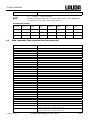
4.5 Read commands (Data requested from the thermostat)
Command Explanation
IN_PV_00 Read bath temperature (outflow temperature)
IN_PV_01 Abfrage der geregelten Temp. (int./ext. Pt/ext. Analogue/ext. Serial)
IN_PV_03 Read external temperature TE (Pt100)
IN_PV_04 Read external temperature TE (Analogue input)
IN_PV_10 Read bath temperature (outflow temperature) in 0.001°C
IN_PV_13 Read external temperature TE (Pt100) in 0.001°C
IN_SP_00 Read temperature setpoint
IN_SP_01 Interrogation of pump power stage
IN_SP_03 Read current overtemperature switch-off point
IN_SP_04 Read current outflow temperature limit TiH.
IN_SP_05 Read current outflow temperature limit TiL.
IN_PAR_00 Read current value of Xp
IN_PAR_01 Read current value of Tn (181 = OFF)
IN_PAR_02 Read current value of Tv
IN_PAR_03 Read current value of Td
IN_PAR_04 Read current value of KpE
IN_PAR_05 Read current value of TnE (999 = OFF)
IN_PAR_06 Read current value of TvE
IN_PAR_07 Read current value of TdE
IN_PAR_09 Interrogation of the max. outflow temperature limit
IN_PAR_10 Read current value of XpF
IN_PAR_11 Read current value of TnF (181 = OFF)
IN_PAR_12 Read current value of TvF
IN_PAR_13 Read current value of TdF
IN_PAR_14 Interrogation of the setpoint offset
IN_DI_01 Status of contact input 1: 0 = open/ 1 = closed
IN_DI_02 Status of contact input 2: 0 = open/ 1 = closed
IN_DI_03 Status of contact input 3: 0 = open/ 1 = closed
IN_DO_01 State of Contact output 1:
0 = make-contact open/ 1 = make-contact closed
IN_DO_02 State of Contact output 2:
0 = make-contact open/ 1 = make-contact closed

Proline Modules
12 Serial interfaces RS232 / 485 YAAE0019 / 08.01.04
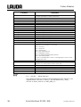
Command Explanation
IN_DO_03 State of Contact output 3:
0 = make-contact open/ 1 = make-contact closed
IN_MODE_00 Keys Master: 0 = free / 1 = inhibited
IN_MODE_01 Control: 0 = int. / 1 = ext. Pt100 / 2 = ext. Analogue / 3 = ext. Serial
IN_MODE_02 Standby: 0 = Unit ON / 1 = Unit OFF
IN_MODE_03 Keys Command: 0 = free / 1 = inhibited
IN_MODE_04 Setpoint offset source: 0=normal/1=ext.Pt/2=ext.analogue/3=ext.serial
TYPE Read equipment type
VERSION_R Read software type of control system
VERSION_S Read software type of protection system
VERSION_B Read software type of Command
VERSION_T Read software type of cooling system
VERSION_A Read software type of analogue module
VERSION_V Read software type of RS232/485 module
VERSION_D Read software type of digital module
STATUS Read equipment status 0 = OK, -1 = error
STAT Read error diagnosis response:
XXXXXXX → X = 0 no error, X = 1, 2, 3 error
Char = error (Exx)
Char = pump error
Char = low level error
Char = over temperature error
Char = refrigeration unit error
Char = no external temperature probe (TE FAIL)
Char = error analogue inputs
0 = OK / 1 = Analogue input 1 < 4mA / 2 = Analogue input 2 < 4mA / 3 = both
Analogue input < 4mA
RMP_IN_00_XXX Read a programme segment XXX
(response: e. g. 030.00_010.00 = 30.00°C and 10 min)
RMP_IN_01 Read the current segment number
RMP_IN_02 Read the set number of programme runs
RMP_IN_03 Read the current programme run
RMP_IN_04 Read the programme to which further instructions apply
RMP_IN_05 Read which programme is running now (0=none)
☞
− For ”_“ use also ” ” (blank character).
− The equipment response is always in the fixed decimal format ”XXX.XX“ or for
negative values “-XXX.XX” or ” ERR_X“. (RS 485 interface e.g.. ”A015_
XXX.XX” or ”A015_-XXX.XX” or ”A015_ERR_X”)

Proline Modules
YAAE0019 / 08.01.04 Serial interfaces RS232 / 485 13
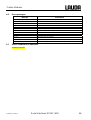
4.6 Error messages
Message Explanation
ERR_2 Wrong input (e.g. buffer overflow)
ERR_3 Wrong command
ERR_5 Syntax error in value
ERR_6 Illegal value
ERR_8 Module (ext. temperature) not available
ERR_30 Programmer, all segments occupied
ERR_31 Set point not possible, analogue set point input ON
ERR_32 TiH <= TiL
ERR_33 No external sensor
ERR_34 Analogue value not available
ERR_35 Auto is selected
ERR_36 No set point input possible. Programmer is running or is paused.
ERR_37 No start from programmer possible, analogue setpoint input is switched on.
4.7 Driver software for LABVIEW®
Available mid-2004.

Proline Modules
14 Analogue module YAAE0019 / 08.01.04
5 Analogue module
The analogue module (order no. LRZ 912) has 2 inputs and 2 outputs which are brought out on a 6-
pole DIN socket to Namur Recommendation (NE28). The inputs and outputs can be set independ-
ently as 4…20 mA, o…20 mA or 0…10V interface. Various functions can be selected for the inputs
and outputs. Accordingly, the signal on the input is interpreted differently and different information is
output via the output connection.
In addition the interfaces can be scaled freely according to the set function.
The following values can be specified via the inputs:
- setpoint temperature with function: or Set temperature
- external actual temperature with function: or ext. actual temperature
- Pump power with function: or Pump power
The following values can be specified via the outputs:
- Setpoint temperature with function: Master: or Command: Set temperature
- The temperature source with which active control occurs: Controlled temp.
- actual temperature (bath temperature): or Internal Temp.
- external actual temperature from Pt100: or Temp.external Pt100
- external actual temperature from analogue input: or Temp.external analogue
- external actual temperature from the serial interface: or Temp.external serial
- actuating signal: or Stellgröße
- Pump power: or Pump power
- Pump speed: or Pump speed
In addition the interfaces can be scaled freely with / in % or minimal value /
maximal value according to the set function.
For example: 4 mA corresponds to 0°C and 20 mA corresponds to 100°C
− Accuracy of the inputs and outputs after calibration better than 0.1% F.S.
☞
− Inputs, current
− Inputs, voltage
− Outputs, current
− Outputs, voltage
Input resistance < 100 Ohm
Input resistance > 50 kOhm
Burden < 400 Ohm
Load > 10 kOhm
Connection of the analogue inputs and outputs
A 6-pole round connector with screw locking and contact arrangement according to DIN 45322 or
IEC 130-9 is needed.
A suitable coupling plug can be obtained under order no. EQS 057.
View of the socket (front) or solder side of plug:
Pin 1 Output 1
Pin 2 Output 2
Pin 3 0V reference potential
Pin 4 Input 1
Pin 5 0V reference potential
Pin 6 Input 2
☞
Use shielded lines. Connect shielding with connector housing!

Proline Modules
YAAE0019/ 08.01.04 Analogue module 15
5.1 Menu structure Analogue module (Master)
All existing menu points are illustrated. However, the Master unit masks out menu points which cannot be
executed.
Actual bath temperature
or actual value of exter-
nal temperature
Configure
modules
: Take setpoint
temperature from input
: Take external actual
temperature from input
: Take pump power (0-
100%) from input
: Output controlled tem-
perature (internal / external Pt /
ext. analogue /ext. serial)
on output
: Output actuating signal
Y on output
: Output pump power (0-
100%) on output
: Output pump speed (0-
100%) on output
: Output setpoint
temperature on output
: Output ext. act. tem-
perature from Pt100 on output
: Output ext. act. tem-
perature from analogue input
on output
: Output ext. actual tem-
perature from serial interface on
output
: Output internal actual
temperature on output
Display level
Set Input 2
Set Output 1
Set Output 2
Set Input 1
Calibrate
inputs and outputs
Restore
factory settings
Quit menu
Configure
analogue module
XX: Set input/output
mode
or : Current ( ) or
voltage ( ) input/output
or : Current input/
output 0-20 or 4-20 mA
: Set maximum value
of the input/output
or : Activate ( );
deactivate ( ) input /output
: Set minimum value
of input/output
Quit settings level
: Calibrate voltage
Input 2
: Calibrate current
Input 1
: Calibrate voltage
Input 1
: Calibrate current
Input 2
: Calibrate voltage
Output 1
: Calibrate current
Output 1
: Calibrate current
Output 2
: Calibrate voltage
Output 2
Quit calibration level
: Display module software
version
: Current on Analogue
Input 1, (if current active)
: Voltage on Analogue
Input 1, (if voltage active)
: Current on Analogue
Input 2, (if current active)
: Voltage on Analogue
Input 2, (if voltage active)
: Setpoint curr. on Ana-
logue Output 1, (if current ac-
: Setpoint volt. on Ana-
logue Output 1, (if volt. active)
: Setpoint curr. on Ana-
logue Output 2, (if current ac-
: Setpoint volt. on Ana-
logue Output 2, (if volt. active)
: Display 24V supply
voltage
: Module serial number
Places 1-5
Quit calibration level
: Module serial number
Places 6-10
corresponds to 20mA or 10V
corresponds to 0mA, 4mA or 0V

Proline Modules
16 Contact module YAAE0019 / 08.01.04
6 Contact module
6.1 Contact module LRZ 915 with three inputs and three outputs
Contact module Cat. no. LRZ 915) on 15 pole SUB-D socket. With three relay contact outputs
(changeover, max. 30V/ 0.2A) and three binary inputs for control via external voltage-free contacts.
The following functions are made available by the inputs:
- set fault with function: Master: or Command: Fault
- set Stand-by with function: or Stand-by
- control programmer with function: or Programmer
- control alternating mode (two different setpoint temperatures): or alternating mode
- controller mode (internal ↔ external control): or type of control
The following functions are made available by the outputs::
- signal various fault states: or fault diagnosis
- signalling standby: or Stand-by
- providing status of the window discriminators (inside ↔ outside): or temperature range
- providing the programmer status: or Programmer
- signalling refill of bath medium: or Refill
Contact inputs and outputs
− View of the socket from the plug side or of the plug on the solder side.
− A suitable 15-pole Sub-D plug can be obtained together with a suit-
able housing:
Order no. EQM 030 and plug housing order no. EQG 017.
1
5V
Input
Output
1 2 3
Contact module LRZ 915; SUB-D
12 4 5 6 13 14 15 7 8
2
5V
3
5V
1 9 2 10 3 11

Proline Modules
YAAE0019/ 08.01.04 Contact module 17
6.2 Namur-Contact module LRZ 914 with only one input and one output
Contact module (Cat. no. LRZ 914) with connector to NAMUR NE28. Functionality as LRZ 915, but
only one output and one input on each of two DIN sockets
Contact inputs and outputs:
Output Input
− View on flange plug (Front) or solder side
coupler socket
− Max. 30V; 0,2A
− Coupler socket Cat. no. EQD 047
− View on flange plug (Front) or solder side cou-
pler socket
− Signal ca. 5V, 10mA. Do not use pin 3!
Coupling plug Cat. no. EQS 048
1 = n.o. (make)
2 = common,
3 = n.c. (break)
☞ − Use shielded lines. Connect shielding with connector housing. Cover unused plug connec-
tions with protecting caps!
5V
1 Input
1 Output
Contact module LRZ 914; DIN sockets
2 1 3 1 2

Proline Modules
18 Contact module YAAE0019 / 08.01.04
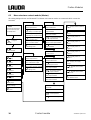
6.3 Menu structure contact module (Master)
All existing dialogue boxes are illustrated. The Master unit however masks out commands which cannot be
executed
Actual bath temperature
or actual value of exter-
nal temperature
Configure
mod
u
les
Configure
contact module
Input switched off : Display module software
version
X: Display status on
Input 1
X: Display status on
Input 2
X: Display status on
Input 3
X: Display status on
Output 1
X: Display status on
Output 2
X: Display status on
Output 3
: Display 24V supply
voltage
: Module serial number
Places 1-5
Quit calibration level
: Module serial number
Places 6-10
Display level
Set Input 2
Set Output 1
Set Input 1
Restore
factory settings
Quit menu
Set Input 3
Set Output 2
Set Output 3
Control type on this
input activated
Alarm function on this
input activated
Stand-by function on
this input activated
Programmer function
on this input activated
Temperature
alternat'g
mode on this input activated
Select , , or as
control source
XXX
Select input function
Quit settings level
only for alternat. mode:
setpt. temp. on 'contact open'
only for alt. mode:
setpt temp on 'contact closed'
only for control type:
type on 'contact open'
only for control type:
type on 'contact closed'
Output switched off
Refill bath liquid on
this output activated
Fault diagnosis mode
Stand-by function on
this output activated
Temperature window
on this output activated
Programmer status on
this output activated
XXX
Select output function
Quit settings level
XXX only when diagnosis
funct. selected for output
only when window
funct active: set temp. window
All alarms, warnings
and faults
Low level alarms
Overtemperature
alarm
All fault messages

Proline Modules
YAAE0019/ 08.01.04 Contact module 19
7 Index
Analogue module........................13
Installation................................... 4
EMC standard EN 61326-1 .......... 3
Hazards........................................ 3
Instructed specialist personnel...... 3
Contact module...........................15
RS232 / 485 Interface Modules .... 6
Safety information ....................... 3
Interface modules......................... 4
Sources of Hazards ...................... 3
Symbol........................................ 2

Seite wird geladen ...
-
 1
1
-
 2
2
-
 3
3
-
 4
4
-
 5
5
-
 6
6
-
 7
7
-
 8
8
-
 9
9
-
 10
10
-
 11
11
-
 12
12
-
 13
13
-
 14
14
-
 15
15
-
 16
16
-
 17
17
-
 18
18
-
 19
19
-
 20
20
-
 21
21


Lauda Proline Accessories Bedienungsanleitung
- Typ
- Bedienungsanleitung
in anderen Sprachen
Verwandte Artikel


Andere Dokumente
-
CARLO GAVAZZI WM4096 Benutzerhandbuch
-
Hamworthy Solar heat meter for RHI Installationsanleitung
-
Eurotherm 3200 Benutzerhandbuch
-
WIKA CPH8000 tag:model:Pascal ET Bedienungsanleitung
-
 RCS AUDIO-SYSTEMS PSB-025 Bedienungsanleitung
-
RCS PSS-224BREV.1.5 Bedienungsanleitung
-
Grundfos CRE Installation And Operating Instructions Manual
-
