
https://tm.by
Интернет-магазин TM.by

https://tm.by
Интернет-магазин TM.by

1
Before the first using your electric storage water heater, carefully read
this Operation Manual
DEAR CLIENT!
Thank you for your purchasing THERMEX electric water heater. We express our
firm believe that the wide range of our water heaters will meet your needs. Use of mod-
ern technologies and best quality materials when manufacturing predetermined popular-
ity of and confidence in THERMEX trademark.
Water heaters THERMEX are designed and manufactured in strict accordance
with domestic and international standards guaranteeing operation reliability and safety.
Present manual shall apply to the following THERMEX models: IF 30 (smart), IF
50 (smart), IF 80 (smart), IF 100 (smart). The full name of the model of your heater is
specified in "Manufaturer’s Warranty" section (sub-section "Note of sale") and in the
marking plate on the heater casing.
APPLICATION
Electric Water Heater (hereinafter EWH) is designed to provide with hot water for
welfare and industrial facilities that have cold water supply main with appropriate char-
acteristics.
EWH shall be operated indoors in heated spaces and it is not designed for opera-
tion in continuous flow mode.
Electric water heater (hereinafter referred to as the EWH) is designed to provide
with hot water for domestic and industrial facilities having a cold water supply line pres-
sure of not less than 0.05 MPa and not more than 0.7 MPa.
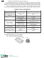
SCOPE OF SUPPLY
1. Water heater ...................................................................
1 pcs.
2. Safety valve of GP type ...................................................
1 pcs.
3. Operation manual ............................................................
1 pcs.
4. Packaging ........................................................................
1 pcs.
5. Anchors for fastening .......................................................
1 set
MAIN TECHNICAL CHARACTERISTICS
EWH power supply voltage of all types and models shall be within the range of 230
V ± 10%. Supply network frequency 50 Hz ± 1%. Volume of the inner tank and heating
element power are specified in the marking plate on the casing. Thread diameter in water
inlet and outlet pipes - G1/2.
The manufacturer reserves the right to make changes to the design, complete set
and specifications of the heater without prior notice.
ы
EN
https://tm.by
Интернет-магазин TM.by

2
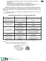
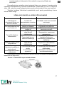
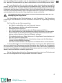
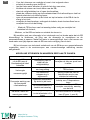
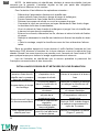
Table 1
Labeling
Average heating time ΔТ = 45° C at 2.0 kW
IF 30 (smart)
39 min.
IF 50 (smart)
1 h. 06 min.
IF 80 (smart)
1 h. 45 min.
IF 100 (smart)
2 h. 12 min.
DESCRIPTION AND PRINCIPLE OF OPERATION
The outside casing of the EWH is made of impact-resistant plastic. Inner tanks
have a special bio-glass-porcelain coating reliably protecting the inner surface against
chemical corrosion. The space between the outside casing and the inner tanks is filled
with polyurethane foam - a modern, ecologically clean thermal insulation, which has the
best heat-saving characteristics. These models have two screwed nozzles: for inlet of
cold water (Figure 1, p. 3) with a blue ring and for outlet of hot water (Figure 1, p. 2) —
with a red ring, and equipped with an additional drain connection (closed with metal plug
button) for draining the water and flushing the inner tank (Figure 1, p. 17). The control
panel, in all models, is on the front side of the EWH (Fig. 1, p. 16).
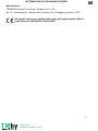
Tubular electric heater (TEH), thermostat and thermal switch sensors are mounted
on the removable flange. TEH is used to heat water and is controlled by thermostat which
has smooth temperature regulation adjustment up to +75°С. All models are controlled
with electronic monitoring panel. Electronics maintain automatically water temperature
at the level set by the user. The thermostat is used for protecting against EWH overheat-
ing, which disconnects TEH from power supply when water temperature exceeds 95°С.
(Fig. 3).
Safety valve (Fig. 1, p. 5) operates as the check valve, ensuring protection of the
water ingress from the water heater into the sewage system in case of pressure drop in
the sewage system and in case of pressure rise in the tank at high water heating, as well
as the functions of the safety valve, releasing overpressure in the tank at high water
heating. During water heater operation water may leak out of the exhaust outlet pipe of
the safety valve to relieve excessive pressure, which is made for the purpose of water
heater safety. This outlet pipe shall remain open to the atmosphere and be installed
constantly down and in a non-freezing environment.
Drainage of water from the safety valve (Fig. 1, p. 14) exhaust pipe into the drain
shall be provided with installation of the corresponding EWH drainage (Fig. 1, p. 6).
It is required regularly (at least once a month) to discharge a small amount of water
through the exhaust pipe of the safety valve into the drain to remove lime deposits and
to test the operating functionality of the valve. Handle (Fig. 1, p. 15) is intended to open
the valve. It is necessary to control when operating water heater this handle to be in
position closing water draining from the tank.
ы
EN
https://tm.by
Интернет-магазин TM.by

3
SPECIFYING SECURITY MEASURES
Electrical safety and corrosion protection of EWH are guaranteed only if there is
an effective grounding in accordance with applicable electric installation rules and regu-
lations.
Plumbing pipes and fittings shall conform to parameters of water main and have
the required certificates of quality.
When installing and operating EWH the following is not allowed:
To power EWH if EWH is not filled with water.
To remove the protective cover when the power is on.
Use EWH without grounding.
To connect EWH to water supply with pressure exceeding 0.7 MPa.
To connect EWH to the water supply without safety valve.
To drain water from EWH with power switched on.
To use spare parts not recommended by the manufacturer.
To use water from the EWH for cooking.
To use water containing impurities (sand, small stones), which might lead to
EWH and safety valve breakdown.
To modify design and installation dimensions of EWH brackets.
Ambient temperature shall be within the range of 3ºС to 40ºС. Water in freezing
EWH at negative temperatures results in malfunction, which is not a warranty case.
Attention should be paid to children so that they do not play with EWH.
EWH is not intended for use by persons (including children) with limited
physical, sensory or mental capabilities, or by persons who do not know
how to use the EWH, except for cases when this happens under the su-
pervision or instructions by persons responsible for safety of the EWH.
INSTALLATION AND CONNECTION
All installation, plumbing and electrical works shall be performed by qualified per-
sonnel.
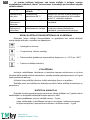
ARRANGEMENT AND INSTALLATION
EWH installation shall be performed in accordance with marking on the housing
and the following table:
Labeling
Arrangement
IF 30 (smart)
vertical installation, pipes down;
Horizontal installation, pipes left
IF 50 (smart)
IF 80 (smart)
IF 100 (smart)
It is recommended to install EWH as close as possible to the place of hot water
using to reduce heat loss in the pipes.
ы
EN
https://tm.by
Интернет-магазин TM.by

4
When drilling (making) holes in the wall consider cables, ducts and pipes in the
wall. When choosing the place of installation total weight of EWH filled with water shall
be taken into account. Walls and floor with low carrying capacity should be strengthened
accordingly.
EWH is suspended by brackets on hook anchors fixed in the wall. Hooks mounting
on the wall shall exclude spontaneous movement of EWH brackets along them.
For EWH maintenance the distance from the protective cover to the nearest sur-
face in the direction of the removable flange axis shall be at least 30 cm for all models.
In order to avoid damage of the user’s and/or third parties’ property in the
event of a faulty hot water system, it is required to install EWH in spaces
with waterproofing and drainage to the sewers, and in no case to place
under items exposed to the water under EWH. When placed in unpro-
tected areas a protective plate (not supplied) with drainage into sewers
shall be installed under the EWH.
In case of placing EWH in hard-to-reach places EVN in order to perform mainte-
nance and warranty service (mezzanine floors, niches, ceiling voids, etc.), installation
and dismantling of EWH is carried out by the user on his own or for his own account.
Note: safety tray is not included into the scope of EWH supply.
CONNECTION TO WATER MAINS
Install pressure relief valve (fig. 1, p.5) at the cold water inlet (fig. 1, p. 3) tube with
the blue ring, by 3.5-4 turnings, ensuring junction tightness with any sealing material
(flax, FUM tape, etc.).
Do not operate the EWH without safety valve or with valve made by other
manufacturers.
During EWH operation you can observe water leak out of the outlet pipe of the
safety valve for excessive pressure release to ensure safety of the water heater. It is
recommended to connect to a drainage hole a rubber or silicone pipe of the relevant
diameter for moisture removal.
Connection to the water supply line shall be carried out in accordance with Fig. 1
using copper, plastic pipes or special flexible sanitary wiring. Do not use any used flexible
wiring. It is recommended to supply water to EWH through filter installed on the cold
water main (not included in the scope of supply).
ы
EN
https://tm.by
Интернет-магазин TM.by

5
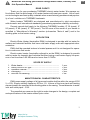
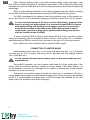
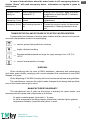
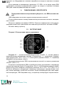
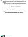
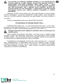
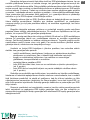
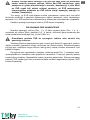
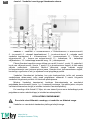
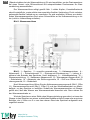
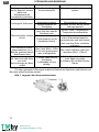
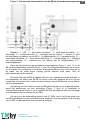
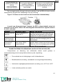
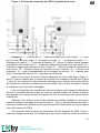
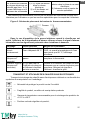
Fig. 1 EWH connection diagram to water supply
Fig. 1: 1 – EWH, 2 – hot water pipe, 3 – cold water pipe, 4 – drain valve, 5
– safety valve, 6 – drainage, 7 – feed pipe, 8 – shut off valve when EWH operation,
9 – cold water main, 10 – hot water main, 11 –cold water shut-off valve, 12 – hot water
shut-off valve, 13 – protective cover, 14 –exhaust pipe of the safety valve, 15 – handle
for opening pressure relief valve, 16 – control panel.
After connection open cold water supply valve (Figure 1, p. 11) in EWH (11), hot
water valve at EWH outlet (Figure 1, p.12) and hot water tap on mixer to ensure outflow
of air from the EWH. When the final EWH filling, cold water will continuously flow out of
mixer tap. Turn the hot water tap on the mixer off.
When connecting EWH in places not provided with water mains it is allowed to
supply water to EWH from auxiliary tank using pumping station, or from the tank placed
at a height of not less than 5 meters from the top of EWH.
Note: for ease of maintenance during EWH operation it is recommended to install
drain valve (Fig. 1, p.4) in accordance with Fig. 1 (for models not equipped with drainage
pipe (not in the scope of EWH supply)).
If water pressure in water supply exceeds 0.7 MPa, pressure relief valve shall be
installed at inlet, upstream of EWH (not in the scope of EWH supply) to reduce water
pressure to standard.
CONNECTION TO POWER SUPPLY
Prior to power activation make sure EWH is filled with water!
ы
EN
https://tm.by
Интернет-магазин TM.by

6
EWH is equipped with the stationary power cable with plug.
Power outlet shall be provided with grounding terminal and be arranged in a dry
place.
Power capacity is 2000W. Power outlet and wiring shall be designed for rated
power at least 2000W.
Plug the device.
OPERATION
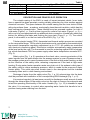
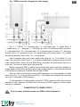
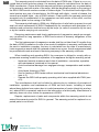
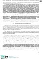
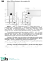
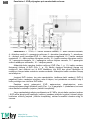
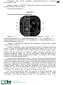
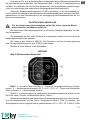
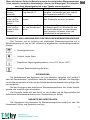
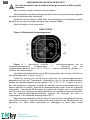
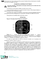
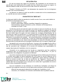
Fig. 2 Electronic control panel
Fig. 2: 1 – “On/Off” on/off button, 2 – “Temperature” heating temperature in-
crease/reduction button, 3 – heating temperature indicators (55°С, 65°С, 75°С), 4 –
“Smart” smart mode button, 5 – “Alarm” emergency alarm indicator.
EWH switching on/off is made by control panel button “On/Off” (Figure 2, p.1).
In the course of EWH operation the user can regulate heating temperature using
button “Temperature” (Figure 2, p. 2). The following values may be taken as target tem-
perature: 55°С, 65°С, 75°С (Figure 2, p. 3). When choosing temperature the heating
temperature indicator flashes 5 times, then switches into operating mode. When water
temperature is lower than the set temperature, EWH heats water, and heating tempera-
ture indicator flashes. When water temperature reaches set value, heating temperature
indicator is permanently on. When water heater is on, its target temperature is 65℃.
Using smart mode button “Smart” (Figure 2, p.4) EWH smart operation mode can
be enabled. In this operation mode EWH can study and record user’s habits in using hot
water and prepare hot water in advance for the next water cycle (7 days in a cycle).
When users do not need hot water, it can maintain water at minimum temperature. Thus
comfort and saving of energy can be achieved. This mode is used for those who use hot
water on a regular basis. To enable this mode, press smart mode button “Smart”. To
disable the mode, press this button again or switch EWH off.
ы
EN
https://tm.by
Интернет-магазин TM.by

7
Frost protection mode “NO FROST”. When EWH is plugged, but switched off using
“On/Off” button, and water temperature is less than 5 ℃ the frost protection mode is
automatically enabled. When water temperature reaches 10 ℃ the frost protection
mode is automatically disabled. When frost protection mode is enabled, power indicator
is on.
If you do not use the EWH in the winter time and there is a possibility of freezing
of the main waterways and the water heater itself, it is recommended to turn off the power
and drain the water from the EWH in order to avoid damage to the inner tank.
TECHNICAL MAINTENANCE
Maintenance and timely replacement of magnesium anode are obligatory condi-
tions for long-term operation of EWH. Failure to comply with these requirements is
grounds for release from the warranty service. Maintenance and replacement of magne-
sium anode are not part of the warranty of the manufacturer.
When performing maintenance condition of magnesium anode and scale on TÈH
are checked. At the same time residue that may accumulate in the bottom of the EWH
is removed.
Magnesium anode must be replaced at least once in 2 years. If water contains high
levels of chemical contaminants, the magnesium anode must be replaced more often.
Scaling at TEH can result in its malfunction, that is not a warranty case, and its replace-
ment is not included in the warranty of the manufacturer and the seller. If there is scale
on TEH, then it can be removed by using scale removing means or mechanically. When
removing residuals from EWH do not apply excessive force and do not use abrasive
cleaners not to damage the protective coating of the inner tank.
Importance of the first maintenance is that by intensity of scale and residues, mag-
nesium anode consumption terms for next maintenance services can be decided and,
consequently, service life can be extended. In case of non-observance of the above re-
quirements EWH service life reduces, increases the probability of EWH breakdown and
validity of warranty expires.
Scale accumulated in the course of operation on TEH may cause its dam-
age
Note: Damages to TEH due to scale formation are not subject to warranty. Regular
maintenance is not included in the warranty of the manufacturer and the seller.
The following shall be carried out for maintenance:
Turn off EWH power;
Cool hot water or discharge it through the mixer;
Cut off supply of cold water into EWH;
Unscrew the relief valve or open drain valve;
To put on the cold water supply inlet or discharge valve a rubber hose, send-
ing the other end down the drain;
Open hot water tap on mixer and drain water from the EWH through the hose;
Remove the protective cover, disconnect wires, unscrew and remove from the
casing the removable flange;
Clean if necessary THEs from scale and remove residue from the tank;
ы
EN
https://tm.by
Интернет-магазин TM.by

8
Assemble, fill the EWH with water and power on.
In models with drain pipe, it is enough to cut off the flow of cold water into the EWH,
unscrew the drain stub on drain pipe and open hot water tap. Once the water is dis-
charged, you can open for a while cold water supply in EWH for additional tank washing.
When conducting EWH maintenance by forces of specialized organization mark
with the seal of organization performing maintenance shall be made in service coupon.
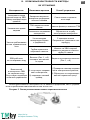
POSSIBLE FAULTS AND REMEDIES.
Malfunction
Possible cause
How to fix
Hot water pressure from
EWH decreased. Cold
water pressure keeps at
the level.
Clogged inlet safety
valve
Remove the valve and clean it in
water
Heating time increased
TEH is covered with a
layer of sludge
Remove the flange and clean
the TEH
Supply voltage de-
creased
Contact power main operation
service
Frequent tripping of
thermal switch
The set temperature is
close to the limit
Reduce temperature using
“Temperature” button
Thermostat tube is cov-
ered with sludge
Take out the EWH the remova-
ble flange and gently clean the
tube from scale
EWH operates but is not
heating water
Valve (Fig. 1, p. 8) is not
closed or out of order
Close or replace the valve (Fig.
1, p. 8)
Powered EWH does not
heat water. No back-
lights of indicator lamps.
1) no voltage in electric
network;
2) damaged power cord.
1) Check voltage at the electri-
cal outlet;
2) Contact a qualified service
center.
These faults are not defects of EWH and shall be fixed by the consumer or by a
specialized organization at his own expense.
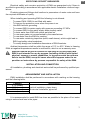
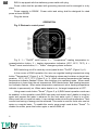
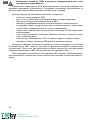
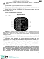
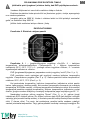
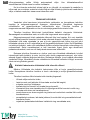
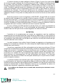
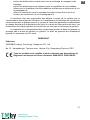
Fig. 3 Thermal switch button layout
Push
ы
EN
https://tm.by
Интернет-магазин TM.by

9
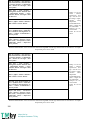
In case of internal failure when the water heater is off, emergency alarm in-
dicator “Alarm” will send emergency alarm. Information on signals is given in
table below:
Indication
Possible cause
How to fix
Indicator is con-
stantly on
Water temperature ex-
ceeded 88 °С
Unplug EWH and plug it again and when
temperature is less than 88°С indication
will discontinue
Indicator flashes
(frequency 1 sec)
Thermostat is malfunc-
tioned
Contact the service center for thermostat
replacement
Indicator flashes
(frequency 4 sec)
No water in the tank
and heating element is
on
Make sure the tank is filled in with water.
Contact the service center for thermostat
replacement, if heating element is burn
out
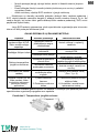
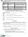
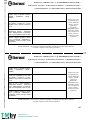
TRANSPORTATION AND STORAGE OF ELECTRIC WATER HEATERS
Transportation and storage of electric water heaters shall be carried out in accord-
ance with manipulation marks on the packaging:
—
need to protect the goods from moisture
—
fragile, delicate handling
—
Recommended temperature range for cargo storage: from +10°С to
+20°С
—
correct vertical position of cargo;
DISPOSAL
When complying with the rules of EWH installation, operation and maintenance
and when water quality complying with current standard the manufacturer sets EWH
lifespan of 9 years.
When disposing of the EWH comply with local environmental laws and guidelines.
The manufacturer reserves the right to make changes to the design and specifica-
tions of the heater without prior notice.
MANUFACTURER'S WARRANTY
The manufacturer sets 2 years as the period of warranty for water heater, and
warranty period for parts and components is as follows:
for water containing tank (inner tank) – 5 years;
for other components (heating element, thermostat, indicator lights, gaskets,
temperature indicator, pressure relief valve) 2 years.
ы
EN
https://tm.by
Интернет-магазин TM.by

10
The warranty period is calculated from the date of EWH sale. If there is no or cor-
rected date of sale and shop stamp, the warranty period is calculated from the date of
EWH manufacture. Claims within the warranty period are accepted only on presentation
of the warranty card with marks of the seller, and the identification plate on the casing of
the EWH. EWH serial number consists of thirteen digits. The third and fourth digits of the
serial number are year of manufacture, the fifth and sixth digits - month of release, the
seventh and eighth digits - day of EWH release. Claims within the warranty period are
accepted only on presentation of the guarantee card with marks of the seller, and the
identification plate on the casing of the EWH.
The warranty shall apply to EWH only. Malfunction of relief valve or power line cord
shall not entail replacement of EWH. Responsibility for compliance with principles of in-
stallation and connection shall be borne by the buyer (in case of connection by his own)
or by the installer carrying out connection.
Recurring maintenance and timely replacement of magnesium anode are compul-
sory conditions for long operation of EWH and survival of warranty obligations of the
manufacturer.
The first replacement of magnesium anode shall be not later than 25 months from
the date of EWH installation (in case of no mark of installation in warranty certificate with
the seal in installation company, the term is calculated from the date of manufacture).
Later magnesium anode shall be replaced at least once a year. Anode replacement shall
be provided with mark and seal of servicing company in the warranty certificate.
When installing and operating EWH, the consumer is obliged to comply with re-
quirements ensuring trouble-free operation of the appliance during the warranty period:
Implement security measures and rules of installation, connection, operation
and maintenance contained in this manual.
Avoid mechanical damage from negligent storage, transportation and installa-
tion.
Avoid water freezing in EWH.
Use for heating in EWH water without mechanical and chemical admixtures
(see cl.5).
Operate the EWH with properly operating relief valve supplied with EWH (see
cl.5).
The manufacturer shall not be liable for defects due to violations of principles of
installation, operation and maintenance of EWH set forth herein, including in cases
where these defects have arisen due to invalid parameters of mains (electricity and wa-
ter), where EWH is operated, and due to the intervention of a third party. Manufacturer’s
warranty does not cover claims for appearance of EWH.
Repairs, replacement of parts and components within the warranty period do not
extend the warranty period for EWH in general. The warranty period for replaced or re-
paired parts is one month.
ы
EN
https://tm.by
Интернет-магазин TM.by

11
INFORMATION ON THE MANUFACTURER
Manufacturer:
THERMEX heating Technology (Jiangmen) CO., Ltd
No. 51, Jianshedonglu, Taoyuan town, Heshan City, Guangdong Province, PRC
All models have been certified and comply with requirements of Euro-
pean Directives 2006/95/EC, 2004/108/EC.
ы
EN
https://tm.by
Интернет-магазин TM.by

12
NOTE OF SALE
Model _________________________ Serial No. ___________________________
Date of sale __________________________________, 20 ______ .
Dealer: __________________________________________________
Dealer's representative
signature ____________________________
The product is completed; I have no claims for the appearance of the product.
Operation manual with the necessary marks is received. I have read, understood and
accepted operation rules and warranty terms.
Customer's signature: ____________________
Dealer's seal
ы
EN
https://tm.by
Интернет-магазин TM.by

13
Перед первым использованием водонагревателя внимательно про-
читайте настоящее руководство по эксплуатации
УВАЖАЕМЫЙ ПОКУПАТЕЛЬ!
Поздравляем Вас с приобретением водонагревателя THERMEX. Выражаем
уверенность в том, что широкий ассортимент наших электроводонагревателей
удовлетворит любые Ваши потребности. Применение современных технологий и
материалов высочайшего качества при изготовлении приборов определили попу-
лярность и доверие к торговой марке THERMEX.
Электроводонагреватели THERMEX разработаны и изготовлены в строгом со-
ответствии с международными стандартами, гарантирующими надежность и без-
опасность эксплуатации.
Настоящее руководство распространяется на следующие модели THERMEX:
IF 30 (smart), IF 50 (smart), IF 80 (smart), IF 100 (smart). Наименование модели при-
обретенного Вами водонагревателя указано в разделе «Отметка о продаже» и в
идентификационной табличке на корпусе прибора.
1. НАЗНАЧЕНИЕ
Электроводонагреватель (далее по тексту ЭВН) предназначен для обеспече-
ния горячей водой бытовых и промышленных объектов, имеющих магистраль хо-
лодного водоснабжения с необходимыми параметрами.
ЭВН должен эксплуатироваться в закрытых отапливаемых помещениях и не
предназначен для работы в непрерывно проточном режиме.
Электроводонагреватель (далее по тексту - ЭВН) предназначен для обеспече-
ния горячей водой бытовых и промышленных объектов, имеющих водопровод хо-
лодной воды с давлением не менее 0,05 МПа и не более 0,7 МПа.
2. КОМПЛЕКТ ПОСТАВКИ
6. Водонагреватель ……........................................1 шт.
7. Предохранительный клапан типа GP...............1 шт.
8. Руководство по эксплуатации...........................1 шт.
9. Упаковка..............................................................1 шт.
10. Анкеры для крепежа...........................................1 комплект
3. ОСНОВНЫЕ ТЕХНИЧЕСКИЕ ХАРАКТЕРИСТИКИ
Напряжение питания всех типов и моделей ЭВН должно находиться в преде-
лах 230 В ±10%. Частота питающей электросети 50Гц ± 1 %. Объем внутреннего
бака и мощность нагревательного элемента указаны в идентификационной таб-
личке на корпусе прибора. Диаметр резьбы патрубков входа и выхода воды –
G1/2.Изготовитель оставляет за собой право на внесение изменений в комплекта-
цию, конструкцию и характеристики водонагревателя без предварительного уве-
домления.
ы
RU
https://tm.by
Интернет-магазин TM.by

14
Таблица 1
Маркировка
Усредненное время нагрева на ΔТ=45°С при мощности 2,0
кВт
IF 30 (smart)
39 мин.
IF 50 (smart)
1 ч. 06 мин.
IF 80 (smart)
1 ч. 45 мин.
IF 100 (smart)
2 ч. 12 мин.
4. ОПИСАНИЕ И ПРИНЦИП ДЕЙСТВИЯ ЭВН
Внешний корпус ЭВН выполнен из ударопрочного пластика. Внутренние баки
имеют специальное покрытие биостеклофарфор, надежно защищающее внутрен-
нюю поверхность от химической коррозии. Пространство между внешним корпусом
и внутренними баками заполнено пенополиуретаном - современной, экологически
чистой теплоизоляцией, обладающей наилучшими характеристиками теплосбере-
жения. Данные модели имеют два резьбовых патрубка: для входа холодной воды
(Рис. 1, п. 3) с синим кольцом и выхода горячей воды (Рис. 1, п. 2) - с красным
кольцом, и оборудованы дополнительным дренажным патрубком (закрыт метал-
лической заглушкой) для слива воды и промывки внутреннего бака (Рис. 1, п. 17).
На лицевой стороне ЭВН, во всех моделях, находится панель управления (Рис. 1,
п. 16).
На съемном фланце смонтированы трубчатый электронагреватель (ТЭН) и
датчики термостата и термовыключателя. ТЭН служит для нагрева воды и управ-
ляется термостатом, который имеет плавную регулировку температуры до +75°С.
Все модели имеют управляются с помощью электронной панели. Электроника ав-
томатически поддерживает температуру воды на уровне, установленном пользо-
вателем. Термовыключатель служит для предохранения ЭВН от перегрева и от-
ключает ТЭН от сети при превышении температуры воды свыше +95°С (Рис. 3).
Предохранительный клапан (Рис. 1, п. 5) выполняет функции обратного кла-
пана, препятствуя попаданию воды из водонагревателя в водопроводную сеть в
случаях падения в последней давления и в случаях возрастания давления в баке
при сильном нагреве воды, а также функции защитного клапана, сбрасывая избы-
точное давление в баке при сильном нагреве воды. Во время работы водонагре-
вателя вода может просачиваться из выпускной трубы предохранительного кла-
пана для сброса излишнего давления, что происходит в целях безопасности водо-
нагревателя. Эта выпускная труба должна оставаться открытой для атмосферы и
быть установлена постоянно вниз и в незамерзающей окружающей среде.
Необходимо обеспечить отвод воды из выпускной трубы предохранительного
клапана (Рис. 1, п. 14) в канализацию, предусмотрев при монтаже ЭВН соответ-
ствующий дренаж (Рис. 1, п. 6).
Необходимо регулярно (не реже одного раза в месяц) проводить слив неболь-
шого количества воды через выпускную трубу предохранительного клапана в ка-
нализацию для удаления известковых осадков и для проверки работоспособности
клапана. Для открывания клапана он снабжен ручкой (Рис. 1, п. 15). Необходимо
следить, чтобы во время работы ЭВН эта ручка находилась в положении, закры-
вающем слив воды из бака.
ы
RU
https://tm.by
Интернет-магазин TM.by

15
5. УКАЗАНИЯ МЕР БЕЗОПАСНОСТИ
Электрическая безопасность ЭВН гарантирована только при наличии эффек-
тивного заземления, выполненного в соответствии с действующими правилами
монтажа электроустановок.
Сантехническая подводка и запорная арматура должны соответствовать пара-
метрам водопроводной сети и иметь необходимые сертификаты качества.
При монтаже и эксплуатации ЭВН не допускается:
подключать электропитание, если ЭВН не заполнен водой;
снимать защитную крышку при включенном электропитании;
использовать ЭВН без заземления;
включать ЭВН в водопроводную сеть с давлением больше 0,7 МПа;
подключать ЭВН к водопроводу без предохранительного клапана;
сливать воду из ЭВН при включенном электропитании;
использовать запасные части, не рекомендованные Производителем;
использовать воду из ЭВН для приготовления пищи;
использовать воду, содержащую механические примеси (песок, мелкие
камни), которые могут привести к нарушению работы ЭВН и предохрани-
тельного клапана.
изменять конструкцию и установочные размеры кронштейнов ЭВН.
Температура окружающей среды, в которой эксплуатируется ЭВН, должна
находиться в пределах от 3ºС до 40ºС. Замерзание воды в ЭВН при отрицательных
температурах приводит к выходу его из строя, что не является гарантийным слу-
чаем.
Следует обращать внимание детей на то, чтобы они не играли с ЭВН.
ЭВН не предназначен для эксплуатации лицами (включая детей) с
ограниченными физическими, осязательными или психическими
способностями, а также лицами, не умеющими пользоваться ЭВН, за
исключением случаев, когда это происходит под наблюдением или
согласно инструкциям от лиц, отвечающих за безопасность ЭВН.
6. УСТАНОВКА И ПОДКЛЮЧЕНИЕ
Все монтажные, сантехнические и электромонтажные работы должны прово-
диться квалифицированным персоналом.
7. РАЗМЕЩЕНИЕ И УСТАНОВКА
Установка ЭВН производится в соответствии с маркировкой, указанной на кор-
пусе, и следующей таблицей:
ы
RU
https://tm.by
Интернет-магазин TM.by

16
Маркировка
Размещение
IF 30 (smart)
вертикальный монтаж, патрубки вниз;
горизонтальный монтаж, патрубки влево
IF 50 (smart)
IF 80 (smart)
IF 100 (smart)
Рекомендуется устанавливать ЭВН максимально близко от места использова-
ния горячей воды, чтобы сократить потери тепла в трубах.
При сверлении (выполнении) отверстий в стене, следует учитывать проходя-
щие в ней кабели, каналы и трубы. При выборе места монтажа необходимо учиты-
вать общий вес ЭВН заполненного водой. Стену и пол со слабой грузоподъемно-
стью необходимо соответственно укрепить.
ЭВН подвешивается за кронштейны корпуса на крюки анкеров, закрепляемые
в стене. Монтаж крюков в стене должен исключать самопроизвольное перемеще-
ние по ним кронштейнов ЭВН.
Для обслуживания ЭВН расстояние от защитной крышки до ближайшей по-
верхности в направлении оси съемного фланца должно быть не менее 30 санти-
метров - для всех моделей;
Во избежание причинения вреда имуществу потребителя и (или) тре-
тьих лиц в случае неисправностей системы горячего водоснабже-
ния, необходимо производить монтаж ЭВН в помещениях, имеющих
гидроизоляцию полов и дренаж в канализацию, и ни в коем случае
не размещать под ЭВН предметы, подверженные воздействию воды.
При размещении ЭВН в незащищенных помещениях необходимо
установить под ЭВН защитный поддон с дренажем в канализацию.
В случае размещения ЭВН в местах, труднодоступных для проведения техни-
ческого и гарантийного обслуживания (антресоли, ниши, межпотолочные про-
странства и т.п.) демонтаж и монтаж ЭВН осуществляется потребителем самосто-
ятельно, либо за его счет.
Примечание: защитный поддон не входит в комплект поставки ЭВН.
8. ПОДКЛЮЧЕНИЕ К ВОДОПРОВОДУ
Установить предохранительный клапан (Рис. 1, п. 5) на входе холодной воды
(Рис. 1, п. 3), помеченном синим кольцом, закрутив на 3,5 - 4 оборота, обеспечив
герметичность соединения любым уплотнительным материалом (льном, лентой
ФУМ и др.).
Запрещается эксплуатировать ЭВН без предохранительного клапана
или использовать клапан других производителей.
Во время эксплуатации ЭВН вы можете наблюдать появление капель из дре-
нажного клювика предохранительного клапана (сброс излишнего давления при
нагреве воды). Рекомендуется присоединить к дренажному клювику резиновую
или силиконовую трубку соответствующего диаметра для отвода влаги.
ы
RU
https://tm.by
Интернет-магазин TM.by

17
Подключение к водопроводной системе производится в соответствии с Рис. 1
только при помощи медных, металлопластиковых или пластиковых труб, а также
специальной гибкой сантехподводки. Запрещается использовать гибкую подводку
бывшую ранее в употребление. Рекомендуется подавать воду в ЭВН через
фильтр-грязевик, установленный на магистрали холодной воды (не входит в ком-
плект поставки).
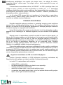
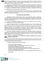
Рисунок 1. Схема подключения ЭВН к водопроводу
Рисунок 1: 1 – ЭВН, 2 – патрубок горячей воды, 3 – патрубок холодной воды,
4 – сливной вентиль, 5 – предохранительный клапан, 6 – дренаж в канализацию,
7 – подводка, 8 – перекрыть вентиль при эксплуатации ЭВН, 9 – магистраль холод-
ной воды, 10 – магистраль горячей воды, 11 – запорный вентиль холодной воды,
12 – запорный вентиль горячей воды, 13 – защитная крышка, 14 – выпускная труба
предохранительного клапана, 15 – ручка для открывания предохранительного кла-
пана, 16 – панель управления.
После подключения откройте вентиль подачи холодной воды (Рис. 1, п. 11) в
ЭВН, кран выхода горячей воды из ЭВН (Рис. 1, п. 12) и кран горячей воды на сме-
сителе, чтобы обеспечить отток воздуха из водонагревателя. При конечном запол-
нении ЭВН из крана смесителя непрерывной струей потечет холодная вода. За-
кройте кран горячей воды на смесителе.
При подключении ЭВН в местах, не снабженных водопроводом, допускается
подавать воду в ЭВН из вспомогательной емкости, размещённой на высоте не ме-
нее 5 метров от верхней точки ЭВН, или с использованием насосной станции.
Примечание: для облегчения обслуживания ЭВН в процессе эксплуатации ре-
комендуется установка сливного вентиля (Рис. 1, п. 4) в соответствии с рис. 1 (для
ы
RU
https://tm.by
Интернет-магазин TM.by

18
моделей, не оборудованных сливным патрубком (не входит в комплект поставки
ЭВН)).
Если давление в водопроводе превышает 0,7 МПа, то на входе перед ЭВН
необходимо установить редукционный клапан (не входит в комплект поставки
ЭВН) для снижения давления воды до нормы.
9. ПОДКЛЮЧЕНИЕ К ЭЛЕКТРОСЕТИ
Перед включением электропитания убедитесь, что ЭВН заполнен во-
дой.
ЭВН оборудован штатным шнуром электропитания с вилкой.
Розетка должна иметь клемму заземления и располагаться в месте, защищен-
ном от влаги.
Мощность прибора составляет 2000 Вт. Розетка и подведенная к ней электро-
проводка должны быть рассчитаны на номинальную мощность не менее 2000Вт.
Вставить вилку в розетку.
10. ЭКСПЛУАТАЦИЯ
Рисунок 2. Электронная панель управления
Рисунок 2: 1 – кнопка включения/выключения «On/Off», 2 – кнопка увеличе-
ния/уменьшения температуры нагрева «Temperature», 3 – индикаторы темпера-
туры нагрева (55°С, 65°С, 75°С), 4 – кнопка умного режима «Smart», 5 – индикатор
аварийной сигнализации «Alarm».
Включение/выключение ЭВН осуществляется кнопкой на панели управления
«On/Off» (Рис.2, п.1).
В процессе эксплуатации ЭВН потребитель может регулировать температуру
нагрева при помощи кнопки «Temperature» (Рис.2, п.2). В качестве целевой темпе-
ратуры могут быть выбраны следующие значения: 55°С, 65°С, 75°С (Рис.2, п.3).
Когда вы выбираете температуру, индикатор температуры нагрева мигает пять
раз, затем переходит в рабочее состояние. Когда температура воды ниже задан-
ной температуры, ЭВН нагревает воду, а индикатор температуры нагрева мигает.
ы
RU
https://tm.by
Интернет-магазин TM.by
Seite wird geladen ...
Seite wird geladen ...
Seite wird geladen ...
Seite wird geladen ...
Seite wird geladen ...
Seite wird geladen ...
Seite wird geladen ...
Seite wird geladen ...
Seite wird geladen ...
Seite wird geladen ...
Seite wird geladen ...
Seite wird geladen ...
Seite wird geladen ...
Seite wird geladen ...
Seite wird geladen ...
Seite wird geladen ...
Seite wird geladen ...
Seite wird geladen ...
Seite wird geladen ...
Seite wird geladen ...
Seite wird geladen ...
Seite wird geladen ...
Seite wird geladen ...
Seite wird geladen ...
Seite wird geladen ...
Seite wird geladen ...
Seite wird geladen ...
Seite wird geladen ...
Seite wird geladen ...
Seite wird geladen ...
Seite wird geladen ...
Seite wird geladen ...
Seite wird geladen ...
Seite wird geladen ...
Seite wird geladen ...
Seite wird geladen ...
Seite wird geladen ...
Seite wird geladen ...
Seite wird geladen ...
Seite wird geladen ...
Seite wird geladen ...
Seite wird geladen ...
Seite wird geladen ...
Seite wird geladen ...
Seite wird geladen ...
Seite wird geladen ...
Seite wird geladen ...
Seite wird geladen ...
Seite wird geladen ...
Seite wird geladen ...
Seite wird geladen ...
Seite wird geladen ...
Seite wird geladen ...
Seite wird geladen ...
Seite wird geladen ...
Seite wird geladen ...
Seite wird geladen ...
Seite wird geladen ...
Seite wird geladen ...
Seite wird geladen ...
Seite wird geladen ...
Seite wird geladen ...
Seite wird geladen ...
Seite wird geladen ...
Seite wird geladen ...
Seite wird geladen ...
Seite wird geladen ...
Seite wird geladen ...
Seite wird geladen ...
Seite wird geladen ...
Seite wird geladen ...
Seite wird geladen ...
Seite wird geladen ...
Seite wird geladen ...
Seite wird geladen ...
Seite wird geladen ...
Seite wird geladen ...
Seite wird geladen ...
Seite wird geladen ...
Seite wird geladen ...
Seite wird geladen ...
Seite wird geladen ...
Seite wird geladen ...
Seite wird geladen ...
-
 1
1
-
 2
2
-
 3
3
-
 4
4
-
 5
5
-
 6
6
-
 7
7
-
 8
8
-
 9
9
-
 10
10
-
 11
11
-
 12
12
-
 13
13
-
 14
14
-
 15
15
-
 16
16
-
 17
17
-
 18
18
-
 19
19
-
 20
20
-
 21
21
-
 22
22
-
 23
23
-
 24
24
-
 25
25
-
 26
26
-
 27
27
-
 28
28
-
 29
29
-
 30
30
-
 31
31
-
 32
32
-
 33
33
-
 34
34
-
 35
35
-
 36
36
-
 37
37
-
 38
38
-
 39
39
-
 40
40
-
 41
41
-
 42
42
-
 43
43
-
 44
44
-
 45
45
-
 46
46
-
 47
47
-
 48
48
-
 49
49
-
 50
50
-
 51
51
-
 52
52
-
 53
53
-
 54
54
-
 55
55
-
 56
56
-
 57
57
-
 58
58
-
 59
59
-
 60
60
-
 61
61
-
 62
62
-
 63
63
-
 64
64
-
 65
65
-
 66
66
-
 67
67
-
 68
68
-
 69
69
-
 70
70
-
 71
71
-
 72
72
-
 73
73
-
 74
74
-
 75
75
-
 76
76
-
 77
77
-
 78
78
-
 79
79
-
 80
80
-
 81
81
-
 82
82
-
 83
83
-
 84
84
-
 85
85
-
 86
86
-
 87
87
-
 88
88
-
 89
89
-
 90
90
-
 91
91
-
 92
92
-
 93
93
-
 94
94
-
 95
95
-
 96
96
-
 97
97
-
 98
98
-
 99
99
-
 100
100
-
 101
101
-
 102
102
-
 103
103
-
 104
104


in anderen Sprachen
- English: Thermex IF 30 User manual
- français: Thermex IF 30 Manuel utilisateur
- Nederlands: Thermex IF 30 Handleiding
- eesti: Thermex IF 30 Kasutusjuhend
Verwandte Artikel
Andere Dokumente
-
ESAB EWH 600 Konformitätserklärung
-
-
ESAB EWT 1000 Benutzerhandbuch
-
ESAB EWH 1000 Single to twin conversion kit Benutzerhandbuch
-
-
-
ESAB EAC 10 Benutzerhandbuch
-
Casio YW-41 Bedienungsanleitung
-
ESAB OPC Flux recovery unit Benutzerhandbuch