
5.1 Allgemein
Das Produkt ist kein Spielzeug. Halten Sie es von Kindern und Haus-
tieren fern.
Lassen Sie Verpackungsmaterial nicht achtlos herumliegen. Dieses
könnte für Kinder zu einem gefährlichen Spielzeug werden.
Falls Sie Fragen haben, die mit diesem Dokument nicht beantwortet
werden können, wenden Sie sich an unseren technischen Kundendi-
enst oder an sonstiges Fachpersonal.
Lassen Sie Wartungs-, Anpassungs- und Reparaturarbeiten auss-
chließlich von einem Fachmann bzw. einer Fachwerkstatt durchführen.
5.2 Handhabung
Gehen Sie stets vorsichtig mit dem Produkt um. Stöße, Schläge oder
das Herunterfallen aus geringer Höhe können das Produkt beschädi-
gen.
Schützen Sie das Produkt vor extremen Temperaturen, starken Stößen,
brennbaren Gasen, Dämpfen und Lösungsmitteln.
Schützen Sie das Produkt vor hoher Feuchtigkeit und Nässe.
5.3 Elektrische Sicherheit
Trennen Sie das Hauptgerät von der Stromversorgung,
bevor Sie an ihm arbeiten. Es besteht Lebensgefahr durch
Stromschlag!
5.4 Heiße Oberächen
Heiße Oberächen und Bauteile können bei Berührung zu
Verbrennungen führen. Lassen Sie heiße Oberächen und
heiße Bauteile auf Raumtemperatur abkühlen, bevor Sie
sie berühren.
6 Entsorgung
Elektronische Geräte sind recycelbar und gehören nicht in den
Hausmüll. Entsorgen Sie das Produkt am Ende seiner Nut-
zungsdauer gemäß den einschlägigen Gesetzen.
7 Technische Daten
Düsentemperatur ........................ max. 400 °C
Lagerbedingungen ...................... +15 bis +35 °C, 30 – 90 % rF
(nicht-kondensierend)
Abmessungen (B x H x T) ..........110 x 250 x 50 mm
Gewicht ....................................... 143 g
Installationsanleitung
Hotend für RF Pro 6
Best.-Nr. 2480782
1 Bestimmungsgemäße Verwendung
Das Produkt ist ein 400 °C Hotend für den 3D Drucker RF Pro 6.
Falls Sie das Produkt für andere als die zuvor genannten Zwecke ver-
wenden, könnte das Produkt beschädigt werden. Unsachgemäßer Ge-
brauch kann zu Kurzschluss, Feuer, Stromschlag oder anderen Gefährdun-
gen führen.
Dieses Produkt entspricht den gesetzlichen, nationalen und europäischen
Anforderungen. Aus Sicherheits- und Zulassungsgründen dürfen Sie dieses
Produkt nicht umbauen und/oder verändern.
Lesen Sie sich die Bedienungsanleitung sorgfältig durch und bewahren Sie
sie sicher auf. Geben Sie das Produkt nur zusammen mit der Bedienung-
sanleitung an Dritte weiter.
Alle enthaltenen Firmennamen und Produktbezeichnungen sind Waren-
zeichen der jeweiligen Inhaber. Alle Rechte vorbehalten.
2 Lieferumfang
Produkt Bedienungsanleitung
3 Neueste Informationen zum Produkt
Laden Sie die neuesten Produktinformationen unter www.conrad.com/
downloads herunter oder scannen Sie den abgebildeten QR-Code. Folgen
Sie den Anweisungen auf der Website.
4 Symbole in diesem Dokument
Dieses Symbol warnt vor Gefahren, die zu Personenschäden
führen können. Lesen Sie die Informationen sorgfältig.
Dieses Symbol warnt vor gefährlicher Spannung, die zu Ver-
letzungen durch Stromschlag führen kann. Lesen Sie die Infor-
mationen sorgfältig.
Dieses Symbol warnt vor heißen Oberächen die bei Berüh-
rung schwere Verbrennungen verursachen können. Lesen Sie
die Informationen sorgfältig.
5 Sicherheitshinweise
Lesen Sie sich die Installationsanleitung sorgfältig durch
und beachten Sie insbesondere die Sicherheitshinweise.
Sollten Sie die in dieser Installationsanleitung enthaltenen
Sicherheitshinweise und Informationen für einen ord-
nungsgemäßen Gebrauch nicht beachten, übernehmen wir
keine Haftung für daraus resultierende Verletzungen oder
Sachschäden. Darüber hinaus erlischt in solchen Fällen
die Gewährleistung/Garantie.
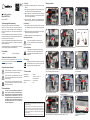
8 Hotend installieren
Lösen Sie die zwei (2x) Schrauben und entfernen Sie die Abdeckung (Abb. 1 und 2). Lösen Sie den Klemmblock des Kühlkörpers.
Befestigen Sie den Fixierschlitz des Extruders
an der Fixierschraube.
Ziehen Sie die Extruderschraube fest.
Lösen Sie die Schrauben des Extruders.
Lösen Sie die Schrauben der unteren
Abdeckung.
Schieben Sie das Hotend nach oben (Abb. 11) und befestigen Sie den Klemmblock
des Kühlkörpers (Abb. 12).
Ziehen Sie die Schrauben an und bringen Sie die Abdeckung an (Abb. 13 und 14).
Setzen Sie das 400 °C Hotend ein. Achten Sie auf die Einbaurichtung: Heizung und Temperaturfühler
müssen nach hinten gerichtet sein (siehe Abb. 8).
Ziehen Sie die Klemmen der Heizung und des NTC ab.
1 2 3
4 5 6260° C 400° C
7 8 9
10 11
2
12
1
13 14 15
Dies ist eine Publikation der Conrad Electronic SE, Klaus-Conrad-Str. 1, D-92240
Hirschau (www.conrad.com).
Alle Rechte einschließlich Übersetzung vorbehalten. Reproduktionen jeder Art, z.
B. Fotokopie, Mikroverlmung, oder die Erfassung in elektronischen Datenverarbei-
tungsanlagen, bedürfen der schriftlichen Genehmigung des Herausgebers. Nach-
druck, auch auszugsweise, verboten. Die Publikation entspricht dem technischen
Stand bei Drucklegung.
Copyright 2021 by Conrad Electronic SE. *2480782_v1_1221_02_jh_im_de_en

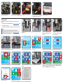
9 Extruder kalibrieren
Nach der Installation des Hotends müssen Sie den Abstand zwischen Sensor und Düse neu
kalibrieren.
1. Laden Sie die Kongurationsdatei cong_KTC.gcode von www.conrad.com/downloads herunter.
2. Laden Sie die Datei in die Firmware.
3. Führen Sie die Z-Offset-Kalibrierung durch. Befolgen Sie die unten aufgeführten Schritte 1 bis 19.
Important:
Wenn Sie das 260 °C Hotend erneut installieren, laden Sie die Kongurationsdatei
cong_NTC.gcode in die Firmware. Laden Sie die Datei von www.conrad.com/downloads
herunter. Führen Sie die Z-Offset-Kalibrierung durch.
Entfernen Sie die untere Abdeckung.
Vergewissern Sie sich, dass der Sensor ca.
1,5 mm höher als die Düse sitzt, und ziehen
Sie dann die Schrauben fest.
Gehen Sie weiter mit Conrm. Gehen Sie zu TOOLS > Leveling.
Lassen Sie die automatische Nivellierungsfunktion laufen, um die Z-Offset-Kalibrierung abzuschließen.
Rufen Sie das Menü auf und gehen Sie zu TOOLS > Preheating.Warten Sie, bis die Temperatur des Druckbetts den voreingestellten Wert erreicht hat (Abb. 9 und 10).
Wählen Sie 0.1 mm (wichtig!). Während Sie das Papier hin- und herschieben, stellen Sie mit
den Bedienelementen
Z
und
Z
den Abstand zwischen Düse und Druckbett ein, bis Sie einen
leichten Widerstand spüren. Speichern Sie den Z-Offset mit .
Gehen Sie auf Manual und drücken Sie das Symbol “Home”. Der Extruder fährt in die Nullposition. Schalten Sie die Z-Offset-Kalibrierung ein. Schieben Sie ein A4-Blatt zwischen die Düse und das
Druckbett.
Legen Sie das Druckbett und die Magnetmatte ein (Abb. 5 und 6).
Legen Sie das Z-Offset-Kalibrierwerkzeug
unter den Sensor und die Düse, um die Höhe
zu kalibrieren.
Ziehen Sie den Anschlussstecker E-TMP(NTC) ab (Abb. 17 und 18). Schließen Sie den Anschlussstecker <E-TMP(KTC)>
an die abgetrennte Klemme (siehe Abb. 18) an.
Bringen Sie die Abdeckung an.
Lösen Sie die Schrauben des Sensors. Stellen Sie sicher, dass sich der Sensor frei auf und ab
bewegen kann.
16 17 18 19 20
1 2 34
1.5mm
5 6
Tools System
Print
7
Filament Stop
Leveling
Preheating
FanS ound
Back
Manual
LED light
8
27/52
1
28/0
9
52/52
1
28/0
10
Filament Stop
Leveling
Preheating
FanS ound
Back
Manual
LED light
11
0.1mm1 mm 10mm
EY
E
Z
Z
Y
X
X
12
1mm 10mm
EY
E
Z
Z
Y
X
X
7
0.1mm
13 14
0.1mm1 mm 10mm
EY
E
Z
Z
Y
X
X
15
0.1mm1 mm 10mm
EY
E
Z
Z
Y
X
X
16
Confirm Cancel
17
Set this position as Z=0, continue?
Filament Stop
Leveling
Preheating
FanS ound
Back
Manual
LED light
18 19

5.1 General information
The device is not a toy. Keep it out of the reach of children and pets.
Do not leave packaging material lying around carelessly. This may be-
come dangerous playing material for children.
If you have questions which remain unanswered by these instructions,
contact our technical support service or other technical personnel.
Maintenance, modications and repairs must only be completed by a
technician or an authorised repair centre.
5.2 Handling
Please handle the product carefully. Jolts, impacts or a fall even from a
low height can damage the product.
Protect the appliance from extreme temperatures, strong jolts, amma-
ble gases, steam and solvents.
Protect the product from high humidity and moisture.
5.3 Electrical safety
Before you work on the main unit, disconnect it from the
power supply.
Danger to life from electric shock!
5.4 Hot surfaces
Hot surfaces and hot components can result in burns if
touched. Let hot surfaces and hot components cool down to
room temperature before touching.
6 Disposal
Electronic devices are recyclable waste and must not be dis-
posed of in the household waste. At the end of its service life,
dispose of the product in accordance with applicable regulatory
guidelines.
7 Technical data
Nozzle temperature .................... max. 400 °C
Storage conditions ...................... +15 to +35 °C, 30 – 90 % RH
(non-condensing)
Dimensions (W x H x D) ............. 110 x 250 x 50 mm
Weight ........................................143 g
Installation Instructions
Hotend for RF Pro 6
Item No. 2480782
1 Intended use
The product is a 400 °C hotend for the RF Pro 6 3D printer.
If you use the product for purposes other than those described, the product
may be damaged. Improper use can result in short circuits, res, electric
shocks or other hazards.
The product complies with the statutory national and European require-
ments. For safety and approval purposes, you must not rebuild and/or
modify the product.
Read the installation instructions carefully and store them in a safe place.
Make this product available to third parties only together with the operating
instructions.
All company names and product names are trademarks of their respective
owners. All rights reserved.
2 Delivery content
Product Operating instructions
3 Latest product information
Download the latest product information at www.conrad.com/downloads or
scan the QR code shown. Follow the instructions on the website.
4 Symbols in this document
The symbol warns of hazards that can lead to personal injury.
Read the information carefully.
The symbol warns of dangerous voltage that can lead to per-
sonal injury by electric shock. Read the information carefully.
The symbol warns of hot surfaces that can result in severe
burns when touched. Read the information carefully.
5 Safety instructions
Read the installation instructions carefully and especially
observe the safety information. If you do not follow the
safety instructions and information on proper handling in
this manual, we assume no liability for any resulting per-
sonal injury or damage to property. Such cases will invali-
date the warranty/guarantee.
This is a publication by Conrad Electronic SE, Klaus-Conrad-Str. 1, D-92240
Hirschau (www.conrad.com). All rights including translation reserved. Reproduc-
tion by any method, e.g. photocopy, microlming, or the capture in electronic data
processing systems require the prior written approval by the editor. Reprinting, also
in part, is prohibited. This publication represents the technical status at the time of
printing. Copyright 2021 by Conrad Electronic SE.
*2480782_v1_1221_02_jh_im_de_en
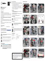
8 Installing the hotend
Loosen the two (2x) screws and remove the cover (g. 1 and 2). Loosen the clamp block of the heatsink.
Fix the locating slot of the extruder to the locat-
ing screw.
Fasten the extruder screw.
Loosen the screws of the extruder.
Loosen the screws of the bottom cover.
Push the hotend to the top (g. 11) and fasten the clamp block of the heatsink (g. 12).
Fasten the screws and install the cover (g. 13 and 14).
Insert the 400 °C hotend. Pay attention to the installation direction: the heater and temperature sensor
must face towards the rear (see g. 8).
Unplug the terminal of heater and NTC.
1 2 3
4 5 6260° C 400° C
7 8 9
10 11
2
12
1
13 14 15

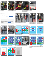
9 Calibrating the extruder
After installing the hotend, you must re-calibrate the distance between the sensor and nozzle.
1. Download the conguration le cong_KTC.gcode from www.conrad.com/downloads.
2. Load the le into the printer rmware.
3. Perform the Z-offset calibration. Follow the steps 1 to 19 shown below.
Important:
If you install the 260 °C hotend again, load the conguration le cong_NTC.gcode into the
printer rmware. You can download the le from www.conrad.com/downloads. Perform the
Z-offset calibration.
Remove the bottom cover.
Make sure the sensor sits approx. 1.5 mm
higher than the nozzle, then fasten the screws.
Continue with Conrm. Go to TOOLS > Leveling.
Let the auto-levelling function run to complete the Z-offset calibration.
Enter the menu and go to TOOLS > Preheating.Wait until the temperature of the print bed reaches the pre-set value (g. 9 and 10).
Select 0.1 mm (important!). While sliding the paper back and forth, use the
Z
Z
controls to
adjust the distance between the nozzle and print bed until you notice light resistance. Save the
Z-offset with .
Go to Manual and press the “Home” icon. The extruder will move to the zero position. Turn on Z-offset calibration. Slide an A4 sheet of paper between the nozzle and the print bed.
Insert the print bed and magnetic mat (g. 5 and 6).
Put the black Z-offset calibration tool under
the sensor and nozzle to calibrate the height.
Disconnect the terminal plug E-TMP(NTC) (g. 17 and 18). Connect the terminal plug <E-TMP(KTC)> to
the disconnected terminal (see g. 18).
Attach the cover.
Loosen the sensor screws. Make sure the sensor can move up and down freely.
16 17 18 19 20
1 2 34
1.5mm
5 6
Tools System
Print
7
Filament Stop
Leveling
Preheating
FanS ound
Back
Manual
LED light
8
27/52
1
28/0
9
52/52
1
28/0
10
Filament Stop
Leveling
Preheating
FanS ound
Back
Manual
LED light
11
0.1mm1 mm 10mm
EY
E
Z
Z
Y
X
X
12
1mm 10mm
EY
E
Z
Z
Y
X
X
7
0.1mm
13 14
0.1mm1 mm 10mm
EY
E
Z
Z
Y
X
X
15
0.1mm1 mm 10mm
EY
E
Z
Z
Y
X
X
16
Confirm Cancel
17
Set this position as Z=0, continue?
Filament Stop
Leveling
Preheating
FanS ound
Back
Manual
LED light
18 19
-
 1
1
-
 2
2
-
 3
3
-
 4
4


