Parkside PDOS 200 B2 Translation Of The Original Instructions
- Kategorie
- Kaffeezubehör
- Typ
- Translation Of The Original Instructions

DOUBLE BENCH GRINDER PDOS 200 B2
IAN 280214
DOUBLE BENCH GRINDER
Translation of the original instructions
DOBBELTSLIBER
Oversættelse af den originale driftsvejledning
DOPPELSCHLEIFER
Originalbetriebsanleitung
DUBBELE SLIJPMACHINE
Vertaling van de originele gebruiksaanwijzing
280214_par_Doppelschleifer_cover_DK_NL.indd 2 29.08.16 16:39

GB / IE / NI Translation of the original instructions Page
DK Oversættelse af den originale driftsvejledning Side
NL Vertaling van de originele gebruiksaanwijzing Pagina
DE / AT / CH Originalbetriebsanleitung Seite
Before reading, unfold the page containing the illustrations and familiarise yourself with all functions of the
device.
Før du læser, vend siden med billeder frem og bliv bekendt med alle apparatets funktioner.
Vouw vóór het lezen de pagina met de afbeeldingen open en maak u vertrouwd met alle functies van het
apparaat.
Klappen Sie vor dem Lesen die Seite mit den Abbildungen aus und machen Sie sich anschließend mit allen
Funktionen des Gerätes vertraut.
280214_par_Doppelschleifer_cover_DK_NL.indd 3 29.08.16 16:39
4
18
32
47

3
1
4 5
7 8
9
10
10
11
12
13
6
3
2
14
14b 14a
2
1
3
3a
5
1
4
2
4a 4b 4c
1
3
10

4
GB IE NI
Introduction
Congratulations on the purchase of your
new device. With it, you have chosen a
high quality product.
During production, this equipment has
been checked for quality and subjected to
a nal inspection. The functionality of your
equipment is therefore guaranteed.
The operating instructions constitute
part of this product. They contain
important information on safety, use
and disposal. Before using the prod-
uct, familiarise yourself with all of
the operating and safety instructions.
Use the product only as described
and for the applications specied.
Keep this manual safely and in the
event that the product is passed on,
hand over all documents to the third
party.
Intended use
The bench double grinder is suitable for
sharpening tools (e.g. knives, scissors,
chisels) and for deburring and grinding of
small workpieces made of metal.
The device is not intended for all other
types of applications (e.g. grinding with
unsuitable grinding tools, grinding with a
coolant solution, grinding hazardous mate-
rials such as asbestos).
The equipment is intended for use in the
eld of DIY. It is not designed for commer-
cial use.
The equipment is designed for use by
adults. Young people over the age of 16
are permitted to use the equipment only
under supervision. The manufacturer shall
not be liable for damages caused by use
other than for the intended purpose or by
incorrect operation.
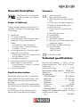
Content
Introduction .................................4
Intended use ................................4
General description ...................... 5
Scope of delivery ............................. 5
Function description.......................... 5
Summary ........................................ 5
Technical specications .................5
Safety Instructions........................6
Symbols and icons ........................... 6
General safety instructions ................ 7
Further Safety Instructions .................. 8
Residual risks ................................... 9
Assembly ................................... 10
Assemble/adjust spark protection .... 10
Assemble/set workpiece supports .... 10
Screw device on to workbench ........ 11
Operation ..................................11
Switching on and off ...................... 11
Grinding with the grinding disc ....... 12
Change grinding disc ..................... 12
Cleaning and maintenance .........13
Cleaning ....................................... 13
General maintenance ..................... 13
Storage ......................................14
Waste disposal and
environmental protection ...........14
Replacement parts/accessories ...14
Trouble Shooting ........................ 15
Guarantee .................................16
Repair Service ............................17
Service-Center ............................ 17
Importer ....................................17
Translation of the original
EC declaration of conformity ......65
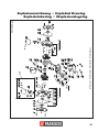
Exploded Drawing ..................... 69

5
NIIEGB
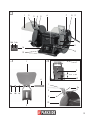
General description
The illustrations can be found
on the front and rear fold-out
pages.
Scope of delivery
Unpack the equipment and check that it is
complete. Dispose of the packaging mate-
rial correctly.
• Appliance
• 2 x spark protection
• mounting material for xing the spark
protection to the spark protection
holder
- 2 x holder for spark protection
- 2 xing screws, 2 spring washers,
2washers, 2 nuts
• mounting material for xing the spark
protection to the device
- 2 adjusting screws incl. washers and
spring washers, 2 nuts
• 2 workpiece supports
• mounting material for xing the work-
piece supports to the device
- 2 star washers, 2 screws, 2 washers,
2 toothed washers
• Instruction Manual
Function description
The double bench grinder is a combined
device tted with two grinding discs with
different grain size for coarse and ne
grinding.
The device is provided with a spark protec-
tion and protective hoods for the protection
of the user.
For the function of the operating parts,
please refer to the descriptions below.
Summary
1 Spark protection
2 Spark protection holder
3 Adjusting screw for spark protec-
tion
4 Fixing screw for spark protection
5 Protective hood grinding disc
6 Motor housing
7 Fixing screws for grinding disc
cover
8 Grinding disc cover
9 Power cable
10 Grinding disc
11 Workpiece support
12 Star grip nut to mount/adjust the
workpiece support
13 Drillholes for table mounting
14 On/off switch
14a On switch
14b Off switch
15 Grinder spindle
Technical specications
Nominal input voltage ......230 V~, 50 Hz
Power consumption ..200 W (S2 30 min)*
Safety class ..........................................I
Mechanical rating .......................... IP 20
Measurement idling speed n
0
... 2950 min
-1
Velocity v
0
.......................... max. 23 m/s
Grinding disc
Outer diameter ...................Ø 150 mm
Bore hole .......................... Ø 12.7 mm
Thickness .................................20 mm
Hardness ....................................... P5
Grain size ................................36/80
Speed n
0
....................max. 4500 rpm
-1
Working speed ................ max. 35 m/s
Weight (incl. accessories) approx. 6.45 kg
Sound pressure level
(L
pA
) ......................................80 dB(A)

6
GB IE NI
Sound power level (L
WA
)
measured ............. 93 dB(A); K
WA
= 3 dB
Vibration total value (a
h
) ......... 2.5 m/s
2
* A break is introduced after 30 minutes of
uninterrupted operating duration until the de-
vice temperature differs 2 K (2°C) less than
room temperature.
Noise and vibration values have been
determined according to the standards and
regulations mentioned in the declaration of
conformity. Technical and optical changes
may be undertaken in the course of further
development without notice. All dimen-
sions, references and information in this
instruction manual are therefore not guar-
anteed. Legal claims made on the basis of
the instruction manual can therefore not be
considered as valid.
The stated vibration emission value was
measured in accordance with a standard
testing procedure and may be used to com-
pare one power tool to another.
The stated vibration emission value may
also be used for a preliminary exposure
assessment.
Warning! The vibration emission
value may differ during actual use
of the power tool from the stated
value depending on the manner in
which the power tool is used.
Safety precautions aimed at protect-
ing the user should be based on
estimated exposure under actual
usage conditions (all parts of the
operating cycle are to be consid-
ered, including, for example, times
during which the power tool is
turned off and times when the tool
is turned on but is running idle).
Safety Instructions
WARNING!
When using power tools, observe
the following basic safety measures
for the prevention of electric shocks
and the risk of injury and re.
Please read all these instructions
before using the electric tools and
please keep the safety instructions.
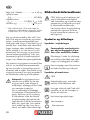
Symbols and icons
Symbols in the manual:
Warning symbols with in-
formation on damage and
injury prevention.
Instruction symbols (the instruction is
explained at the place of the excla-
mation mark) with information on
preventing damage.
Help symbols with information on
improving tool handling.
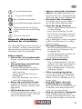
Symbols on the device:
Warning!
Risk of injury from the rotating tool!
Keep hands away.
Risk of electric shock! Disconnect
from the mains before carrying out
maintenance and repair work.
Read the instruction manual.
Wear ear protection.
Wear eye protection.

7
NIIEGB
Wear breathing protection.
Wear cut-resistant gloves.
Wear anti-slip safety shoes.
Never use faulty grinding discs.
Do not dispose of electrical equip-
ment in household waste.
Dimensions grinding disc
General safety instructions
The term “power tool” used in the safety in-
structions refers to mains-operated electric
tools (with a mains cable) and to battery-
operated electric tools (without a mains
cable).
Safe operation:
• Keep work area clear. Cluttered
areas and benches invite injuries.
• Consider work area environ-
ment.
- Do not expose tools to rain.
- Do not use tools in damp or wet loca-
tions.
Water entering a power tool will in-
crease the risk of electric shock.
- Keep work area well lit.
- Do not use tools in the presence of
ammable liquids or gases.
Power tools create sparks which may
ignite the dust or fumes.
• Guard against electric shock.
Avoid body contact with earthed or
grounded surfaces (e.g. pipes, radia-
tors, ranges, refrigerators).
• Keep other persons away.
Do not let persons, especially children,
not involved in the work touch the tool
or the extension cord and keep them
away from the work area.
• Store idle tools. When not in use,
tools should be stored in a dry locked-
up place, out of reach of children.
• Do not force the tool. It will do
the job better and safer at the rate for
which it was intended.
• Use the right tool.
- Do not force small tools to do the job
of a heavy duty tool.
- Do not use tools for purposes not
intended; for example do not use cir-
cular saws to cut tree limbs or logs.
Use of the power tool for operations dif-
ferent from those intended could result in
a hazardous situation.
• Dress properly.
- Do not wear loose clothing or jewel-
lery, they can be caught in moving
parts.
- Anti-slip footwear is recommended
when working outdoors.
- Wear protective hair covering to con-
tain long hair.
• Use protective equipment.
- Use safety glasses.
- Use face or dust mask if working op-
erations create dust.
• Connect dust extraction equip-
ment. If the tool is provided for the
connection of dust extraction and col-
lecting equipment, ensure these are
connected and properly used.
• Do not abuse the cord. Never
yank the cord do disconnect it from the
socket. Keep the cord away from heat,
oil and sham edges.
• Secure work. Where possible use
clamps or a vice to hold the work. It is
safer than using your hand.

8
GB IE NI
• Do not overreach. Keep proper
footing and balance at all times.
This enables better control of the power
tool in unexpected situations.
• Maintain tools with care.
Many accidents are caused by poorly
maintained power tools.
- Keep cutting tools sharp and clean
for better and safer performance.
- Follow instruction for lubricating and
changing accessories.
- Inspect tool cords periodically and if
damaged have them repaired by an
authorized service facility.
- Inspect extension cords periodically
and replace if damaged.
- Keep handles dry, clean and free
from oil and grease.
• Disconnect tools. When not in use,
before servicing and when changing
accessories disconnect tools from the
power supply.
Such preventive safety measures reduce
the risk of starting the power tool acci-
dentaIly.
• Remove adjusting keys and
wrenches. Form the habit of check-
ing to see that keys and adjusting
wrenches are removed from the tool
before turning it on. A wrench or a key
left attached to a rotating part of the
power tool may result in personal injury.
• Avoid unintentional starting.
Ensure switch is in “off” position when
plugging in.
• Use outdoor extension leads.
When the tool is used outdoors, use
only extension cords intended for out-
door use and so marked.
• Stay alert, watch what you are
doing and use common sense
when operating a power tool.
Do not use a power tool while you are
tired or under the inuence of drugs,
alcohol or medication. A moment of
inattention white operating power tools
may result in serious personal injury.
• Check damaged parts.
This will ensure that the safety of the
power tool is maintained.
- Before further use of tool, it should be
carefully checked to determine that it
will operate properly and perform its
intended function.
- Check for alignment of moving parts,
binding of moving parts, breakage of
parts, mounting and any other condi-
tions that may affect its operation.
- A guard or other part that is dam-
aged should be properly repaired or
replaced by an authorized service
centre unless otherwise indicated in
this instruction manual.
- Do not use the tool if the switch does
not turn it on and off. Have defective
switches replaced by an authorized
service centre. There is a risk of injury.
• Warning.
The use of any accessory or attach-
ment other than one recommended in
this instruction manual may present a
risk of personal injury.
• Have your tool repaired by a
qualied person. This electric tool
complies with the relevant safety rules.
Repairs should only be carried out by
qualied persons using original spare
parts, otherwise this may result in con-
siderable danger to the user.
Further Safety Instructions
• Connect the device only to a power
point with a residual current protective
device (RCD) with a measured residual
current of not more than 30 mA.
• Keep the mains cable and extension
cable away from the grinding disc.

9
NIIEGB
In the event that it is damaged or sev-
ered, immediately disconnect the plug
from the socket.
Do not touch the cable before it has
been disconnected from the mains.
Risk of electric shock.
• The replacement of the plug or the con-
nection line must always be executed
by the manufacturer of the electric tool
or his/her customer service in order to
avoid any hazards.
• Only switch the device on once it is
safely xed to the worktop.
• For your own safety only use acces-
sories and attachments which were
stated in the operating instructions or
recommended or specied by the tool
manufacturer.
• Only use grinding tools recommended
by the manufacturer. Do not use any
saw blades. Ensure that the dimensions
match those of the device.
• Only use grinding discs where the
printed rotational speed is at least as
high as what has been specied on the
name plate of the device.
• Carry out a visual inspection of the
grinding disc before use. Do not use
any damaged or deformed grinding
discs. Replace any damaged or worn
grinding discs.
• Never operate the device without
spark protection or protective hoods.
Periodically readjust the spark protection
in order to offset the wear and tear of
the grinding disc (distance max. 2 mm).
• Replace the grinding disc if the spark
protection and the workpiece support
can no longer be readjusted to a dis-
tance of max. 2 mm at the latest.
• Make sure that the sparks produced
by grinding do not present a danger,
e.g. reach people or ignite ammable
substances.
• Always wear safety goggles, safety
gloves, respiratory protection and ear
protection when grinding, brushing and
separating.
• Never keep the ngers between the
grinding disc and spark protection or in
close proximity to the protective hoods.
There is a risk of crushing.
• The rotating parts of the device cannot
be covered due to functional reasons.
Therefore, proceed cautiously and hold
the workpiece rmly in order to avoid
slipping which could cause your hands to
come into contact with the grinding disc.
• The workpiece gets hot during grinding.
Do not touch the machined area, allow
it to cool down. There is a risk of burn-
ing. Do not use coolants or the like.
• If you are tired or have consumed al-
cohol or tablets, do not work with the
device. Always have a break on time.
• Switch the device off and remove the
mains plug
- to loosen a blocked insertion tool,
- if the connection line is damaged or
entangled,
- in case of unusual sounds.
Residual risks
Even if properly operating and handling
this electric tool, some residual risks will
remain. Due to its construction and build,
this electric tool may present the following
hazards:
a) Lung damage, if suitable respiratory
protection is not worn.
b) Hearing damage, if suitable ear protec-
tion is not worn.
c) Damages to health due to
- touching the area of the grinding tool
which was not covered;

1 0
GB IE NI
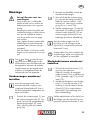
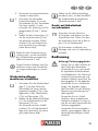
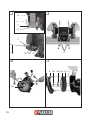
Assemble/adjust spark
protection
You will need a screwdriver and a
spanner (size 8 mm) (sold separate-
ly) to use as a counter holder to t
the above.
1. Screw the spark protection (1) to
the spark protection holder (2). To
do this, use the xing screws (4),
nut (4a), spring washer (4b) and
washer (4c) supplied.
2. Fit the second spark protection in
a similar manner.
3. Screw the spark protection holder
(1) rmly to the protective hood
(5). To do this, use 1 adjusting
screw including the spring washer
and at washer (3) and 1nut (3a)
for each.
4. Adjust the spark protection (1)
with the adjusting screw (3) - the
distance between the grinding
disc (10) and the spark protection
must be max. 2 mm (see small
image).
Periodically readjust the spark pro-
tection in order to offset the wear
and tear of the grinding disc (dis-
tance max. 2mm).
Despite the spark protection, you
should always wear safety glasses
when working in order to avoid eye
injuries.
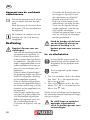
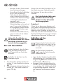
Assemble/set workpiece
supports
1. Screw the workpiece supports
(11) on to the device.
- the ejection of pieces from workpiece
or damaged grinding discs.
d) Damage to your health caused by
swinging your hands and arms when
operating the appliance for longer pe-
riods of time or if the unit is not held or
maintained properly.
Warning! During operation, this
electric tool generates an electro-
magnetic eld which, under certain
circumstances, may impair the
functionality of active or passive
medical implants. To reduce the risk
of serious or lethal injuries, we rec-
ommend that persons with medical
implants consult their doctor and the
manufacturer of their medical im-
plant before operating the machine.
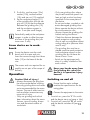
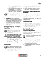
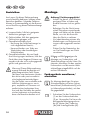
Assembly
Caution! Risk of injury!
- Ensure that you have sufcient
space in which to work, and that
you do not endanger other people.
- Always fasten the device on to
the work surface with screws
featuring the sufcient length and
thickness in order to maintain
control of the device.
- All covers and protective devices
must be assembled properly be-
fore commissioning.
- Disconnect the mains plug before
changing the setting on the de-
vice.
Figure and Figure show
how to t the spark protection and
workpiece support on the left-hand
side of the device. Fit the second
spark protection and the second
workpiece support

1 1
NIIEGB
2. To do this, use the screw (12a),
washer (12b), toothed washer
(12c) and star nut (12) supplied.
3. Set the workpiece support (11)
of the grinding disc with the star
grip nut (12) so that the distance
between the grinding disc (10)
and the workpiece support is
max. 2 mm (see small image).
Periodically readjust the workpiece
support in order to offset the wear
and tear of the grinding disc (dis-
tance max. 2 mm).
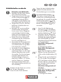
Screw device on to work-
bench
Screw the device onto the work-
bench with 4 screws and nuts.
Insert the screws through the 4 bore
holes (13) on the base of the de-
vice.
The screws and nuts required for as-
sembly are not part of the scope of
delivery.
Operation
Caution! Risk of injury!
- Always disconnect the plug from
the mains socket before working.
- Use only grinding discs and acces-
sories recommended by the manu-
facturer. The use of other insertion
tools and other accessories may
cause risk of injury.
- Only use grinding tools which
bear information about the manu-
facturer, type of binding, dimen-
sion and permitted number of
revolutions.
- Only use grinding discs where
the printed rotational speed is at
least as high as what has been
specied on the name plate of
the device.
- Do not use broken, cracked or oth-
erwise damaged grinding discs.
- Never operate the device without
the visual protection disc.
- Always inspect the grinding disc
before starting the device:
Check the distance between the
spark protection and grinding
disc as well as workpiece support
and grinding disc (distance maxi-
mum 2 mm).
- The grinding disc must be re-
placed once the spark protection
and workpiece support on the
grinding disc do not have dis-
tance of max. 2 mm.
- Switch on the equipment only
when it is safely installed on the
work surface.
Keep your hands away from
the grinding disc when the
device is in operation. Injury
hazard!
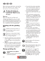
Switching on and off
Ensure that the mains voltage
matches the specications on the
rating plate.
Connect the equipment to the mains.
1. To switch on, press the “I” On switch
and the device starts up (see
14a).
2. To switch off, press the “0” off switch
and the device switches off (see
14b).

1 2
GB IE NI
After switching on the device, wait until the
device has reached its max. speed. Only
then must you start with the grinding.
The disc will continue to
run after the equipment is
switched off. There is a risk
of injury.
Test run:
Before starting work and after each
change of grinding disc, carry out a test
run of at least 60 seconds with no load.
Switch off the equipment immediately if the
disc runs lumpy, substantial vibrations oc-
cur, or abnormal noises are generated.
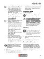
Grinding with the grinding
disc
Fold down the spark protector (1)
when grinding in order to avoid
injury from sparks.
The arrow on the protective hood
(
5) shows the direction of rota-
tion of the grinding disc.
• Place the workpiece on the workpiece
support (
11) and slowly bring it to
its desired angle on the grinding disc
(
10).
• Move the workpiece slightly from side
to side in order to achieve an optimal
grinding result. This way, the grinding
disc is worn uniformly. Occasionally,
allow the workpiece to cool down.
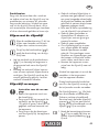
Change grinding disc
Information on replace-
ment:
• Never operate the device without
protective equipment.
• Ensure that the rotation speed stat-
ed on the grinding disc (
10) is
the same or higher than the nomi-
nal rotation speed of the device.
• Ensure that the grinding disc
dimensions match those of the de-
vice.
• Only use awless grinding discs
(sound test: an undamaged grind-
ing disc hanging freely on a string
will result in a clear sound if it is
tapped with a plastic hammer).
• Never re-drill a locating hole
which is too small to make it
larger.
• Never use separate bushings or
adapters in order to make grind-
ing discs whose hole is too large
t the device.
• Do not use any saw blades.
• To clamp the grinding tools only
use the clamping ange provided.
The pads between the clamping
ange and the grinding tools must
be made of elastic materials e.g.,
rubber, soft cardboard etc.
• Always reassemble the device
completely after replacing the
grinding disc.
Switch the device off and remove
the mains plug.
Allow the device to cool down.
Wear protective gloves when chang-
ing the grinding discs in order to
avoid cutting damages.
The grinding disc nuts ( 10a)
have different threads (left-hand
and right-hand threads). To avoid
damaging the grinding disc spindle
thread (
15), never mix up the
two grinding disc nuts (
10a).

1 3
NIIEGB
1. Undo the xing screws ( 7) and
remove the left-hand and right-
hand grinding disc cover (
8).
2. Unscrew the grinding disc nuts
(10a) by counter-holding the nut
on the opposite grinding disc with
a spanner (size 19 mm).
Unscrewing the left-hand nut (left-
hand thread):
turn clockwise.
Unscrewing the right-hand nut
(right-hand thread):
turn anticlockwise.
3. Remove the clamping ange (10b)
and the grinding disc (10).
4. Set up the new grinding disc (10)
with the intermediate shims (10c)
made of cardboard and the clam-
ping ange (10b) and manually
screw the grinding disc nut (10a)
on.
Screwing the left-hand nut (left-
hand thread) on:
turn anticlockwise.
Screwing the right-hand nut (right-
hand thread) on:
turn clockwise.
5. Screw the left hand and right
hand grinding disc covers (8) on.
6. Adjust the spark protection (
1)
and the workpiece support (
11) - the distance to the grinding
disc (10) is max. 2 mm (see „As-
sembly“)
The grinding disc nut must not be
screwed too tightly in order to
avoid a breaking of the grinding
disc and nut.
7. Test run:
Before starting work and after each
change of grinding disc, carry out a
test run of at least 60 seconds with no
load. Switch off the equipment immedi-
ately if the disc runs lumpy, substantial
vibrations occur, or abnormal noises
are generated.
Cleaning and
maintenance
Disconnect the plug before adjust-
ment, maintenance or repair.
Have any work not described
in these instructions carried
out by a specialist workshop.
Use only original components.
Allow the equipment to cool
before carrying out any main-
tenance and cleaning work.
There is a risk of burns.
Cleaning
Do not use cleaning agents or sol-
vents. Chemical substances may
attack plastic parts of the equipment.
Never clean the equipment under
running water.
• Clean the equipment thoroughly after
each use.
• Clean the surface of the equipment
with a brush or cloth.
General maintenance
Before each use, check the equipment
for obvious defects such as loose, worn
or damaged components and check that
screws or other parts are sitting correctly.
In particular, check the grinding disc (
10). Replace damaged parts.

1 4
GB IE NI
Storage
• Store the appliance in a dry place well
out of reach of children.
• Grinding discs must be stored dry and
upright and are not to be stacked.
Waste disposal and en-
vironmental protection
Be environmentally friendly. Return the tool,
accessories and packaging to a recycling
centre when you have nished with them.
Machines are not to be place with
domestic waste.
Hand over the device at an utilization loca-
tion. The plastic and metal parts employed
can be separated out into pure materials
and recycling can be implemented. Ask your
Service Center about this. Defective units re-
turned to us will be disposed of for free.
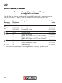
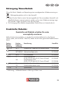
Replacement parts/accessories
Spare parts and accessories can be obtained at
www.grizzly-service.eu
If you do not have internet access, please contact the Service Centre via telephone
(see “Service-Center” page 17). Please have the order number mentioned below ready.
Position Position Description Order
Instruction Exploded number
manual drawing
1,2,3 SET1 Spark protection, holder and adjusting screw 91103556
11 SET3 LEFT Workpiece support, left 91103558
SET3 RIGHT Workpiece support, right 91103559
14 SET2 On/off-switch 91103557
10 5 Grinding disc, left
(G 36 / Ø 150 mm x Ø 12,7 mm x 20 mm)* 91103553
28 Grinding disc, right
(G 80 / Ø 150 mm x Ø 12,7 mm x 20 mm)* 91103554
10a 3 Grinding disc nut, left 91103551
29 Grinding disc nut, right 91103555
10b 4 Clamping ange 91103552
* G = granulation / external diameter x hole x thickness in mm

1 5
NIIEGB
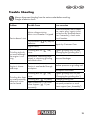
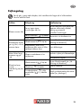
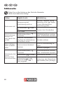
Trouble Shooting
Always disconnect the plug from the mains socket before working.
Danger of electric shock.
Problem Possible Cause Error correction
Device doesn‘t start
Mains voltage missing
Main circuit breaker is tripped
Check the socket, mains cable,
line, mains plug, repairs to be
carried out by qualied electri-
cian if necessary, check main
circuit breaker.
On/off switch (
14) may be
defective
Repair by Customer Care
Engine faulty
Grinding tools do
not move although
the engine is run-
ning
Grinding disc nut (
10a)
loose
Tighten grinding disc nut (see
„Changing the grinding disc“)
Workpiece, remaining work-
pieces or remaining grinding
tools block drive
Remove blockages
Engine is slower
and stops
Device is overloaded through
workpiece
Reduce pressure on grinding tool
Workpiece unsuitable
Grinding disc does
not rotate smoothly,
abnormal noises
can be heard
Grinding disc nut (
10a)
loose
Tighten grinding disc nut (see
„Changing the grinding disc“)
Grinding disc (
10) faulty
Change grinding disc
Spark protection (1) or work-
piece support (
11) set
incorrectly
Set spark protection or work-
piece support (see „Assembly“)

1 6
GB IE NI
Guarantee
Dear Customer, this equipment is provided
with a 3-year guarantee from the date of
purchase. In case of defects, you have stat-
utory rights against the seller of the prod-
uct. These statutory rights are not restricted
by our guarantee presented below.
Terms of Guarantee
The term of the guarantee begins on the
date of purchase. Please retain the original
receipt. This document is required as proof
of purchase.
If a material or manufacturing defect occurs
within three years of the date of purchase
of this product, we will repair or replace –
at our choice – the product for you free of
charge. This guarantee requires the defec-
tive equipment and proof of purchase to be
presented within the three-year period with
a brief written description of what consti-
tutes the defect and when it occurred.
If the defect is covered by our guarantee, you
will receive either the repaired product or a
new product. No new guarantee period be-
gins on repair or replacement of the product.
Guarantee Period and Statutory
Claims for Defects
The guarantee period is not extended by
the guarantee service. This also applies for
replaced or repaired parts. Any damages
and defects already present at the time of
purchase must be reported immediately af-
ter unpacking. Repairs arising after expiry
of the guarantee period are chargeable.
Guarantee Cover
The equipment has been carefully produced
in accordance with strict quality guidelines
and conscientiously checked prior to delivery.
The guarantee applies for all material and
manufacturing defects. This guarantee
does not extend to cover product parts that
are subject to normal wear and may there-
fore be considered as wearing parts (e.g.
grinding discs, carbon brushes, stopper,
protective screen) or to cover damage to
breakable parts (e.g. switches).
This guarantee shall be invalid if the prod-
uct has been damaged, used incorrectly or
not maintained. Precise adherence to all of
the instructions specied in the operating
manual is required for proper use of the
product. Intended uses and actions against
which the operating manual advises or
warns must be categorically avoided.
The product is designed only for private and
not commercial use. The guarantee will be
invalidated in case of misuse or improper han-
dling, use of force, or interventions not under-
taken by our authorised service branch.
Processing in Case of Guarantee
To ensure quick handling of you issue,
please follow the following directions:
• Please have the receipt and identica-
tion number (IAN 280214) ready as
proof of purchase for all enquiries.
• Please nd the item number on the rat-
ing plate.
• Should functional errors or other de-
fects occur, please initially contact the
service department specied below by
telephone or by e-mail. You will then
receive further information on the pro-
cessing of your complaint.
• After consultation with our customer
service, a product recorded as defective
can be sent postage paid to the service
address communicated to you, with the
proof of purchase (receipt) and speci-
cation of what constitutes the defect

1 7
NIIEGB
and when it occurred. In order to avoid
acceptance problems and additional
costs, please be sure to use only the ad-
dress communicated to you. Ensure that
the consignment is not sent carriage
forward or by bulky goods, express or
other special freight. Please send the
equipment inc. all accessories supplied
at the time of purchase and ensure ad-
equate, safe transport packaging.
Repair Service
For a charge, repairs not covered by the
guarantee can be carried out by our ser-
vice branch, which will be happy to issue
a cost estimate for you. We can handle
only equipment that has been sent with ad-
equate packaging and postage.
Attention: Please send your equipment to
our service branch in clean condition and
with an indication of the defect.
Equipment sent carriage forward or by
bulky goods, express or other special
freight will not be accepted.
We will dispose of your defective devices
free of charge when you send them to us.
Service-Center
GB
Service Great Britain
Tel.: 0871 5000 720
(£ 0.10/Min.)
E-Mail: [email protected]
IAN 280214
NI
IE
Service Ireland
Service Northern Ireland
Tel.: 1890 930 034
(0,08 EUR/Min., (peak))
(0,06 EUR/Min., (off peak))
E-Mail: [email protected]
IAN 280214
Importer
Please note that the following address is
not a service address. Please initially con-
tact the service centre specied above.
Grizzly Tools GmbH & Co. KG
Stockstädter Straße 20
D-63762 Großostheim
Germany
www.grizzly-service.eu

1 8
D K
Indhold
Introduktion ...............................18
Anvendelsesformål ....................18
Generel beskrivelse ................... 19
Leveringsomfang ............................19
Funktionsbeskrivelse .......................19
Oversigt ........................................19
Tekniske data ............................19
Sikkerhedsinformationer ............20
Symboler og billedtegn ...................20
Generelle sikkerhedsinformationer
for el-værktøjer ..............................21
Yderligere sikkerhedshenvisninger ....22
Restrisici .......................................23
Montage .................................... 24
Montering/indstilling af
gnistbeskyttelse ..............................24
Montering/indstilling af emneholder ..24
Fastskruning af sliberen til
arbejdsbordet ................................25
Betjening ...................................25
Til- og frakobling ............................25
Slibning med slibeskiven .................26
Udskiftning af slibeskive ..................26
Rengøring og vedligeholdelse ....27
Rengøring .....................................27
Generelle vedligeholdelsesarbejder ..27
Opbevaring ...............................27
Bortskaffelse/miljøbeskyttelse ... 27
Reservedele/Tilbehør ................. 28
Fejlsøgning ................................29
Garanti ......................................30
Reparations-service ....................31
Service-Center ............................ 31
Importør ....................................31
Oversættelse af den originale
CE-konformitetserklæring ...........67
Eksplosionstegning ...................69
Introduktion
Hjertelig tillykke med købet af dit nye ap-
parat.Du har besluttet dig for et produkt af
højeste kvalitet.
Dette apparats kvalitet blev kontrolleret un-
der produktionen og det blev underkastet
en slutkontrol. Dermed er dit apparats funk-
tionsevne garanteret.
Betjeningsvejledningen er bestand-
del af dette produkt. Den indeholder
vigtige informationer vedrørende
sikkerhed, brug, vedligeholdelse og
bortskaffelse. Gør dig inden brugen
af produktet fortrolig med alle betje-
nings- og sikkerheds-informationer.
Benyt kun produktet som beskrevet
og kun til de anførte indsatsområder.
Opbevar vejledningen godt og lad
alle dokumenter følge med ved vide-
regivelse af produktet til tredje.
Anvendelsesformål
Dobbeltsliberen er beregnet til slibning af
værktøj (f.eks. knive, sakse, mejsler) og til
afgratning og slibning af mindre emner i
metal.
Elværktøjet er ikke beregnet til andre
anvendelsesformer (f.eks. slibning med
ikke egnet slibeværktøj, slibning med et
kølemiddel, slibning af sundhedsskadelige
materialer som asbest).
Apparatet er kun beregnet til hobbymæssig
brug. Der er ikke konstrueret til permanent
erhvervsmæssig brug.
Maskinen må kun anvendes af voksne.
Unge over 16 år må kun anvende maski-
nen under opsyn af en voksen.
Producenten påtager sig intet ansvar for
skader, der forårsages på grund af ukor-
rekt brug eller forkert betjening.

1 9
D K
Generel beskrivelse
Illustrationerne nder du på de
forreste og bagerste foldesider.
Leveringsomfang
Kontrollér indholdet ved udpakningen af
maskinen. Bortskaf indpakningsmaterialet
forskriftsmæssigt.
• Apparat
• 2 x gnistbeskyttelse
• Monteringsmateriale til fastgørelse af
gnistbeskyttelsen på gnistbeskyttelses-
holderen
- 2 x holder til gnistbeskyttelse
- 2 fastspændingsskruer, 2 fjeder-
ringe, 2 underlagsskiver, 2 møtrikker
• Monteringsmateriale til fastgørelse af
gnistbeskyttelse på dobbeltsliberen
- 4 justeringsskruer inkl. underlagsskiver
og fjederringe, 4 møtrikker
• 2 emneholdere
• Monteringsmateriale til fastgørelse af
emneholdere på dobbeltsliberen
- 2 stjernemøtrikker, 2 skruer, 2 under-
lagsskiver, 2 tandskiver
• Betjeningsvejledning
Funktionsbeskrivelse
Dobbeltsliberen er en kombimaskine, der
er udstyret med to slibeskiver med forskel-
lig kornstørrelse til grov- og nslibning.
Til beskyttelse af brugeren er sliberen
udstyret med gnistbeskyttelse og beskyttel-
sesskærm.
Betjeningsdelenes funktion forklares i de
efterfølgende beskrivelser.
Oversigt
1 Gnistbeskyttelse
2 Gnistbeskyttelsesholder
3 Justeringsskruer til
gnistbeskyttelse
4 Fastgørelsesskrue til
gnistbeskyttelse
5 Beskyttelsesskærm slibeskive
6 Motorhus
7 Fastgørelsesskruer til
slibeskiveafdækning
8 Slibeskiveafdækning
9 Strømkabel
10 Slibeskive
11 Emneholder
12 Stjernemøtrik til montering/juste-
ring af emneholder
13 Huller til bordmontage
14 Tænd/slukknap
14a Tændknap
14b Slukknap
15 Slibespindel
Tekniske data
Nominel spænding ...........230 V~, 50 Hz
Effektforbrug .............................. 200 W
(S2 30 min)*
Kapslingsklasse ..................................... I
Beskyttelsestype ............................. IP 20
Beregnet tomgangsomdrejningstal
n
0
...................................... 2950 min
-1
Omløbshastighed v
0
.................... 23 m/s
Slibeskiver
Udvendig diameter.............. Ø 150 mm
Boring .............................. Ø 12,7 mm
Tykkelse ...................................20 mm
Hårdhedsgrad ................................ P5
Kornstørrelse ............................36/80
Omdrejningstal n
0
..... maks. 4500 min
-
1
Arbejdshastighed ............maks. 35 m/s

2 0
D K
Vægt (inkl. tilbehør) ...............ca. 6,45 kg
Lydtryksniveau
(L
pA
) ...................................... 80 dB(A)
Lydeffektniveau
(L
WA
) .................... 93 dB(A); K
WA
= 3 dB
Vibration (a
h
) .......................... 2,5 m/s
2
* Efter uafbrudt drift i 30 minutter følger en
driftspause, indtil sliberens temperatur afviger
mindre end 2 K (2°C) fra rumtemperaturen.
Støj- og vibrationsværdier blev målt i hen-
hold til de angivne standarder og bestem-
melser i overensstemmelseserklæringen.
Ændringer med hensyn til teknikken og ud-
seendet kan i forbindelse med videreudvik-
lingen foretages uden meddelelse herom.
Derfor påtager vi os intet ansvar for alle
dimensioner, henvisninger og angivelser
i denne betjeningsvejledning. Krav, som
fremsættes på grund af betjeningsvejled-
ningen, kan således ikke gøres gældende.
Den anførte svingningsemissionsværdi blev
målt iht. en standardiseret prøvemetode
og kan anvendes til sammenligning af et
el-værktøj med et andet. Den anførte sving-
ningsemissionsværdi kan også anvendes til
en indledende vurdering af afbrydelsen.
Advarsel: Svingningsemissions-
værdien kan adskille sig fra den
angivne værdi under brugen af
el-værktøjet, afhængig af den måde
som værktøjet bruges på.
Der er nødvendigt af fastlægge
forholdsregler til beskyttelse af bru-
geren, der beror på en vurdering
af afbrydelsen under de faktiske
brugsbetingelser (derved skal der
tages hensyn til alle driftscyklussens
dele, dvs. også tider, hvor værktø-
jet er slukket og tider, hvor det er
tændt, men kører uden belastning).
Sikkerhedsinformationer
OBS! Ved brug af el-værktøjer skal
man til beskyttelse mod elektrisk
stød, kvæstelses- og brandfare være
opmærksom på følgende principiel-
le sikkerhedsforanstaltninger:
Læs venligst denne brugsvejledning
opmærksomt igennem før første
brug af apparatet et opbevar vej-
ledningen på.
Symboler og billedtegn
Symboler i vejledningen
Faresymboler med oplysnin-
ger om forebyggelse af per-
son- eller materielle skader.
Påbudstegn (i stedet for udråbsteg-
net forklares påbuddet) med oplys-
ninger om forebyggelse af skader.
Henvisningstegn med informationer
om bedre håndtering af udstyret.
Symboler på maskinen:
OBS!
Kvæstelsesfare pga. roterende
værktøj! Hold hænderne væk.
Fare pga. elektrisk stød! Træk altid
netstikket ud, før der foretages ar-
bejder på maskinen.
Læs betjeningsvejledningen.
Bær høreværn.
Bær øjenværn
Seite wird geladen ...
Seite wird geladen ...
Seite wird geladen ...
Seite wird geladen ...
Seite wird geladen ...
Seite wird geladen ...
Seite wird geladen ...
Seite wird geladen ...
Seite wird geladen ...
Seite wird geladen ...
Seite wird geladen ...
Seite wird geladen ...
Seite wird geladen ...
Seite wird geladen ...
Seite wird geladen ...
Seite wird geladen ...
Seite wird geladen ...
Seite wird geladen ...
Seite wird geladen ...
Seite wird geladen ...
Seite wird geladen ...
Seite wird geladen ...
Seite wird geladen ...
Seite wird geladen ...
Seite wird geladen ...
Seite wird geladen ...
Seite wird geladen ...
Seite wird geladen ...
Seite wird geladen ...
Seite wird geladen ...
Seite wird geladen ...
Seite wird geladen ...
Seite wird geladen ...
Seite wird geladen ...
Seite wird geladen ...
Seite wird geladen ...
Seite wird geladen ...
Seite wird geladen ...
Seite wird geladen ...
Seite wird geladen ...
Seite wird geladen ...
Seite wird geladen ...
Seite wird geladen ...
Seite wird geladen ...
Seite wird geladen ...
Seite wird geladen ...
Seite wird geladen ...
Seite wird geladen ...
Seite wird geladen ...
Seite wird geladen ...
Seite wird geladen ...
Seite wird geladen ...
-
 1
1
-
 2
2
-
 3
3
-
 4
4
-
 5
5
-
 6
6
-
 7
7
-
 8
8
-
 9
9
-
 10
10
-
 11
11
-
 12
12
-
 13
13
-
 14
14
-
 15
15
-
 16
16
-
 17
17
-
 18
18
-
 19
19
-
 20
20
-
 21
21
-
 22
22
-
 23
23
-
 24
24
-
 25
25
-
 26
26
-
 27
27
-
 28
28
-
 29
29
-
 30
30
-
 31
31
-
 32
32
-
 33
33
-
 34
34
-
 35
35
-
 36
36
-
 37
37
-
 38
38
-
 39
39
-
 40
40
-
 41
41
-
 42
42
-
 43
43
-
 44
44
-
 45
45
-
 46
46
-
 47
47
-
 48
48
-
 49
49
-
 50
50
-
 51
51
-
 52
52
-
 53
53
-
 54
54
-
 55
55
-
 56
56
-
 57
57
-
 58
58
-
 59
59
-
 60
60
-
 61
61
-
 62
62
-
 63
63
-
 64
64
-
 65
65
-
 66
66
-
 67
67
-
 68
68
-
 69
69
-
 70
70
-
 71
71
-
 72
72


Parkside PDOS 200 B2 Translation Of The Original Instructions
- Kategorie
- Kaffeezubehör
- Typ
- Translation Of The Original Instructions
in anderen Sprachen
- English: Parkside PDOS 200 B2
- Nederlands: Parkside PDOS 200 B2
- dansk: Parkside PDOS 200 B2
Verwandte Artikel
-
Parkside PDOS 200 B2 Translation Of The Original Instructions
-
-
-
-
Parkside PNTS 250 B1 Translation Of The Original Instructions
-
Parkside PDFW 120 A1 Translation Of The Original Instructions
-
Parkside PNTS 250 A1 Translation Of The Original Instructions
-
-
Parkside 113076 Translation Of The Original Instructions
-
