Wavetek 225A Bedienungsanleitung
- Kategorie
- Multimeter
- Typ
- Bedienungsanleitung
Dieses Handbuch ist auch geeignet für

Operator’s Manual
Model RMS225A
Autoranging Digital
Multimeter
• Bedienungsanleitung
• Manual de Instrucciones
• Manuel d’Utilisation
¤
TM
Digital MultiMeter/MultiTester
RMS225A.Man.07.00 11/30/00 8:30 PM Page 1

WARRANT Y
The RMS225A Di gi t al Mul t i meter i s war rant ed agai nst any def ect s of mater i al or
wor kmanshi p wi t h i n a per i od o f o ne ( 1) year f ol l o wi n g t h e d ate o f p ur ch ase o f t he mu l t i met er
by the ori ginal purchaser or ori ginal user.
Any mul t i met er cl ai med t o b e def ect i v e d ur i n g t h e war r an t y p er i o d shoul d b e r et u r ned wi t h
proof of purchase to an authori zed Wavetek Meterman Service Center or to the l ocal Wavetek
Meterman dealer or distributor where your mul timeter was purchased. See maintenance
section for detail s.
Any i mpl i ed war r ant i es ar i si ng ou t of t h e sal e of a W
avet ek M et er man mu l t i met er , including
but not l imited to i mpl ied warranti es of merchantabil ity and fi tness for a parti cular purpose, are
limited in duration to the above stated one (1) year period. Wavetek Meterman shall not be
liable for loss of use of the multimeter or other incidental or consequential damages,
expenses, or economi cal l oss or f or an y cl ai m or cl ai ms f or such damage, ex penses or
economi c al l o ss .
Some s t at es do n ot al l ow l i mi t at i o ns on h ow l ong i mpl i ed war r an t i es l as t o r t h e excl u si o n
or limitati on of i ncidental or consequenti al damages, so the above li mi tati ons or exclusi ons
may not appl y t o yo u.
Thi s war r ant y gi ves you s pec i f i c l egal r i g ht s , and you may al s o h ave ot her r i g ht s whi ch var y
from state to state.
D GEWÄHRLEI STUNG
Di e Di gi t al e Mul t i met er Model l e RMS225A i st ab Kauf dat um f ür ei n ( 1) Jahr gegen
Materi al- und Herstell ungsfehl er gewährleistet. Siehe Kapitel "Unterhalt und Reparatur" für
Ei nz e l h e i t e n.
Implizierte Schadeforderungen sind auch auf ein Jahr beschränkt. W
avet ek Met er man i s t ni ch t
anspr ech bar f ü r Geb r auc hs ver l u ß od er Fol geschäden, Aus gab en, Gewi n nv er l u ß, us w.
E GAR ANT I A
Est e Mul t ím e t r o D i gi t a l e Mode l o RMS 2 2 5A es t á g a r a n t i z a do cont r a c u a l q ui e r d e f e c t o de
mat er i al o d e mano de o br a d ur an t e un per i o do de u n ( 1 ) añ o c on t ado a p ar t i r d e l a f ech a d e
adqui s i c i ó n. En l a s ecc i ó n d e " M ant en i mi ent o y Rep ar aci ó n" se expl i c an l os det al l es r el at i vos
a r epar aci o nes en g ar ant í a.
Cual qui er ot r a gar ant í a i mp l í ci t a es t á t ambi én l i mi t ada al per i odo c i t ado de un ( 1) año.
Wav et ek Met er man n o se har á r es po ns abl e de p ér di d as de u so d el mul t í met r o, n i de ni n gú n
otro daño acci dental o consecuencial, gastos o pérdi das económicas, en ni nguna reclamación
a que pudi er a h aber l u gar p or di c hos dañ os , gas t os o p ér di d as ec on ómi cas.
F GARANTIE
Le multi mètre digi taux, Modèle RMS225A est garanti pour un (1) an à parti r de l a date
d’achat contre les défauts de matériaux et de fabrication. Voi r chapitre "Maintenance et
Ré pa r a t i o n" p o ur pl u s d e dé t a i l s .
T
oute garanti e i mpl iquée est égal ement l imitée à un an. Wav etek M et er man n e p eut êt r e
tenu responsable pour perte d’utilisation ou autres préjudices indirects, frais, perte de
bénéfi ce, etc.
RMS225A.Man.07.00 11/30/00 8:30 PM Page 2

CONTENTS
Introduction ........................................ 2
Saf et y I nf or mat i on . . . . . . . . . . . . . . . . . . . . . . . . . . . . . . 2
Instrument Familiarization................... 5
Measurement Procedures ................. 10
Menu Functions ............................... 20
Speci f i cat i ons . . . . . . . . . . . . . . . . . . . . . . . . . . . . . . . . . . . . 27
Maintenance and Repair ................... 35
D • Inhal t
Ei n l e i t ung . . . . . . . . . . . . . . . . . . . . . . . . . . . . . . . . . . . . . . . . . . . 2
Si c her h ei t s i n f or mat i onen . . . . . . . . . . . . . . . . . . . . 3
Vo r s t el l u n g d es Gerät es . . .. . .. . . .. . .. . . .. . .. . . 5
Meßprozeduren ................................ 10
Menü-Funkti onen ............................. 21
Spezi f i kat i o nen . . . . . . . . . . . . . . . . . . . . . . . . . . . . . . . . . 29
Wa r t u ng u nd Repar a t u r . . . . . . . . . . . . . . . . . . . . . 3 5
E • Contenidos
Introducción ....................................... 2
Información de seguridad ................... 4
Fami l i ar i zaci ó n c on el i nst r u ment o . . . . . . . 5
Pr ocedi mi en t os de med i d a . . . . . . . . . . . . . . . 1 1
Funci ones d e menú . . . . . . . . . . . . . . . . . . . . . . . . . . 2 1
Espe c i f i c a ci o n e s . . . . . . . . . . . . . . . . . . . . . . . . . . . . . . . . 31
Mantenimiento y reparación ............. 35
F • Contenu
Introduction..........................................3
Informations de Sécurité ..................... 4
Pr ésent at i on de l ’ Ap par ei l . . . . . . . . . . . . . . . . . . . 5
Pr océdu r es d e Mes ur e . . . . . . . . . . . . . . . . . . . . . . 1 1
Fonct i ons d e Men u. . . . . . . . . . . . . . . . . . . . . . . . . . . . . 22
Spéci f i cat i ons . . . . . . . . . . . . . . . . . . . . . . . . . . . . . . . . . . . 33
Maintenance et Réparati on ............... 35
EXPLANATI ON OF SY M BOLS
D • Er kl är u ng der Sy mbol e = E • Si gni f i cado d e l o s s ímbol o s = F • Ex pl i c at i o n d es Sy mbo l es
At t ent i o n! Ref er t o Oper at i n g I n st r u ct i ons • D• Ac ht u ng ! Bi t t e An l ei t u ng l es en
•E• ¡At enci ó n! Co ns ul t e l as I nst r ucci o nes de Us o •F• At t ent i on! Consu l t ez l e
manuel .
Gr ound conne ct i o n • D • Er d a nschl u ß •E• Conexi ó n a t i er r a
•F• Connect i o n de t er r e.
Al t er nat i n g c ur r en t • D• Wech sel s t r om •E• Cor r i ent e al t er na
•F• Cour ant al t er nat i f .
Di r ect cur r ent • D• Gl e i c hst r om •E• Co r ri en t e co nt i n ua
•F• Cour ant cont i n u.
Danger ous vol t ag e may be pr esent at t er mi n al s • D• Ei n e g e f ä hr l i c he S pa nnung
kann an den Ei ngängen anli egen •E• Pu ede h aber t en si ón pel i g r os a en l o s
terminales •F• Une t ensi on danger euse peu t êt r e pr ésent e aux ent r ées.
Low battery symbol • D• En t l a de n e B a t t e r i ea nz e i g e •E• Sí mbol o de p i l a b aj a
•F• Symbol e d e pi l e déchar gée.
Thi s i n st r u ment h as d ou bl e i n su l at i on • D• Di eses Ger ät i st doppel t g ei s ol i er t
•E• Est e i nst r um e nt o t i e ne d obl e a i s l am i e nt o •F• Cet appar ei l est pr évu d’ une
double i solati on.
- 1 -
RMS225A.Man.07.00 11/30/00 8:30 PM Page 3

WARNI NGS AND P RECAUT I ONS
■ Thi s i n st r u ment i s EN61 01 0- 1/ CE cer t i f i ed f or I nst al l at i on Cl as s I I , 1 00 0V and
Cl ass II I, 600V. I t i s r ecommended f or use i n di st ri buti on l evel and f i xed
installations, as well as lesser installations, and not for primary supply lines,
overhead li nes and cable systems. ■ Al l i n pu t s ar e p r ot ec t ed agai nst c ont i nu ou s
overload condi ti ons up to the l imits of each functi on's stated input protection (see
specifi cations). Never exceed these l imits
nor the rati ngs marked on the
instrument itself. ■ Fo r vol t age measu rement s, th e ci r cui t u nder t est mus t be
protected by a 20A fuse or circuit breaker. ■ Ex e r c i s e e xt r e m e ca ut i o n w he n:
INTRODUCTION
The Wav et ek di gi t al mul t i met er RMS2 25 A i s a 4- di gi t , au t or ang i n g, AC- cou pl ed
true RMS measuring instrument that measures voltage, current, resistance,
continui ty and di ode juncti ons. Menu selection all ows Range Lock, Probe Hold,
Re l at i v e Me a sur e m e nt , A ut o Mi n Ma x Me a s u r e m e n t a nd ba ckl i g ht on/ of f . T he
instrument is completely sealed.
D • Einl ei tung
Das Wavet ek Mo del l RMS22 5A i st ei n 4- st el l i g es AC- geko ppel t es, ech t- ef f ekt i v-
wert messende Di gi t al mul t i meter mi t aut omat i scher Berei chswahl . Es mi ßt
Spannung, St r om, Wi der st and und Dur chgang und f ühr t Di odent est aus. Ei ne
Menüwahl umfaßt Bereichssperre, Meßwertspeicher, Relativmessung, Auto Min
Max. und Anzeigen-Rückbeleuchtung. Das Gerät i st vollständig abgedichtet.
E • I nt r odu cc i ó n
El m u l t í m et r o d i g i t a l Wave te k RM S 2 25 A est á i n s t r u m en t o d e 4 d í g i t o s , c on
selección automáti ca de escala y medida de verdadero valor eficaz con
acopl ami en t o en CA. M i d en t en si ón, c or r i ent e, r es i s t enc i a, c on t i n ui dad y un i o nes
de diodo. El menú de selección permite acti var bl oqueo de escala, retención de
sonda, medi das relati vas, medidas automáti cas mín/máx y i luminación de pantall a.
El i n st r um e n t o e st á com pl e t a m e nt e se l l a do .
D • Introduction
Le modèle RMS225A de Wavetek est un multi mètre numéri que 4-di gits à sélection
aut omat i que d es gammes , mesur ant l a val eur ef f i cace- vr ai e avec coupl age CA. I l
mesur e l a t en si on, l e c ou r ant , l a r és i s t anc e et l a cont i n ui t é, et ef f ect ue d es t est s d e
diodes. Un menu de foncti ons comprend le bloquage de gamme, l e mainti en de
lecture, la mesure relative, Auto Min Max et un rétro-éclairage de l’afficheur.
L’ i n st r um ent est com p l è te me n t é tanche .
- 2 -
RMS225A.Man.07.00 11/30/00 8:30 PM Page 4

measur i ng vol t age >20V, cur r ent >10mA, AC power l i ne wi t h i n du ct i ve l oads, AC
power line duri ng electrical storms. High voltages can be lethal and high vol tage
transients may occur at any time. ■ Ope r a t or i n j ur y o r d a m a ge to t he m u l t i m e t e r
may o cc ur du r i ng cur r ent meas ur emen t s i f t he f us e b l o ws i n a ci r c ui t wi t h op en
circui t voltage >600V (500V in mA i nput). ■ Al ways i ns pect your DMM, t est
leads and accessories for signs of damage or abnormality before every use. If an
abno r mal condi t i on exi st s ( br ok en or damag ed t est l ead s, cr acked case, di s pl ay
not reading, etc.), do not use. ■ Whe n t e st i ng f or vol t a ge or cur r e nt , m a ke s ur e
these ranges function correctly. Take a reading of a known voltage or current first.
■ Never gr ound your sel f when t aki ng measur ement s. Do not t ouch exposed
met al pi pes, ou tl et s, f i xt ur es, et c. , whi ch mi g ht be at g r ou nd po t ent i al . Keep you r
body isolated from ground and never touch exposed wiring, connections, test
probe tips, or any l ive ci rcui t conductors. Do not use the Flex-Strap to attach the
met er t o yo ur b od y. ■ Al way s meas ur e cu r r ent i n s er i es wi t h t he l oad – NEVER
connect the multimeter ACROSS a voltage source. Check fuse first. ■ Never
replace a fuse with one of a different rating. ■ Do not oper at e i n st r u ment i n an
expl os i v e at mo sp her e ( f l ammab l e g ases , f u mes, v apo r, d us t . ) ■ Do no t u se t h i s
or any piece of test equipment wi thout proper training ■ CRT SERVI CE SAFETY
REMI N D ER : A pot e nt i a l da nge r ex i st s wh e n m e a sur i ng v ol t a ge s i n t he h or i z ont a l
output and damper stages of CRT equipment. (High voltage transi ents greater than
6,000 V). Refer to your CRT service manual for proper servici ng i nstructions.
D • Warnungen und Vorsichtsmaßnahmen
■
Di es es Ger ät i st EN61 01 0- 1/ CE zer t i f i zi er t f ür I n st al l at i onskl asse I I , 10 00V un d
Kl as se I I I , 600V. Anwen du ng i s t empf ohl en au f Ver t ei l er ebene un d f est en Anl ag en
sowie untergeordneten Systemen, jedoch nicht für Starkstromnetze und Hoch-
spannungsanlagen.
■
Über schr ei t en Si e ni e d i e kon ti nui er l i c hen Üb er l as t gr enzen
der verschi edenen Meßfunktionen (siehe Spezifi kationen) oder andere Grenzen
wel che auf dem Gerät mar ki er t si nd.
■
Für Spannungsmessungen muß der
Meßkreis mit einer 20A Sicherung oder einem Trennschalter abgeschirmt sein.
■
Vo r s i c ht b ei m M es s en vo n Sp ann un gen > 20 V / / St r ö men >1 0mA / / Net zs t r o m/ -
spannung bei induktiver Last oder bei Gewittern // Strom, wenn die Si cherung
durchbrennt in einem Schaltkreis mit Leerlaufspannung >600V (>500V beim mA
Ei n g an g ) / / b ei m M e s s en an Bi l d r ö h r g er ä t en ( h o h e Sp a n n u n g s s p i t ze n )
■
Unser suc hen Si e Ger ät , M eßkabel , Ver bi n der, u sw. v or j ed er Mes sun g. Bes ch ädi gt e
Te i l e ni cht ve r w en d en
■
Meßspitzen und Stromkreis während der Messung nicht
berühren • Sich selbst i solieren ! Das Gerät nicht mit der Trageschl aufe am eigenen
Kör per bef es t i g en.
■
Bei St r o mmess un g, M ul t i met er i mmer i n Ser i e mi t Sc hal t kr ei s
verbinden – Nie in parallel mit Spannungsquelle.
■
Si cher ung i mmer mi t
glei chwerti ger ersetzen.
■
Ge r ä t ni cht i n e xpl o si ve r U m ge bun g v e r w e nde n.
- 3 -
RMS225A.Man.07.00 11/30/00 8:30 PM Page 5

E• Advertencias y Precauciones
■
Est e i nst r um e nt o e s t á hom ol o g a do s e gún EN 610 10- 1/ C E pa r a l a C a t e gor í a de
Instalación II - 1000V o Categoría de Instalación III - 600V. Su uso está
recomendado en el nivel de distribución y en instalaciones fijas, así como en
instalaciones menores, pero no en líneas principales de suministro, líneas aéreas ni
sistemas de cabl e.
■
No s up er e nunca l o s l í mi t es de en t r ada par a l as di f er en tes
funciones (vea Especificaciones), ni los límites marcados en el instrumento.
■
Par a
medi das de t ensi ón, el ci r cu i t o somet i d o a pr ueba debe est ar pr ot egi d o con un
fusible de 20 A o un disyuntor.
■
Te n g a e speci al c ui da d o al : me d i r t en s i ón >2 0 V / /
corriente >10 mA / / tensión de red de CA con cargas inductivas // tensión de red de
CA d ur ant e t or men tas el éct r i cas / / co r r i en t e, si s al t a el f us i b l e en un ci r c ui t o c on
tensión de circuito abierto >600 V (500 V en la entrada de mA) // trabajar con
pantall as TRC
■
Inspeccione siempre el multímetro, las puntas de prueba, los
conectores y los accesorios antes de cada uso. No util ice ningún componente que
est é d añad o.
■
No s e ponga Ud. a t i er r a c uan do est é t oman do medi das, y no t oque
nunca partes expuestas de los ci rcui tos. No uti lice la cinta “ Fl ex- Strap” para suj etar
el mu l t í met r o a su c uer p o.
■
Al med i r c or r i ent e, c on ect e s i emp r e el mu l t í met r o EN
SERI E co n l a car ga - NUNCA EN PARAL EL O c on u na f u ent e d e t en si ón.
■
Nunca
sustituya un fusible con otro que no tenga las mismas especifi caciones.
■
No
util ice el instrumento en ambi entes potencial mente explosivos.
F • Avertissements et Précauti ons
■
Cet i ns tr ument es t cer t i f i é EN610 10- 1/ CE c atégo ri e d’ i ns tal l at i o n I I , 1000 o u
catégori e III, 600V. Son uti lisati on est recommandée pour le niveau de distri buti on
de réseau, les install ations fixes et systèmes subordonnés, et non pour l es
installations de puissance et lignes de transmission et câblages à haute tension.
■
N’ excédez j amai s l es l i mi t es d e sur char ge co nt i nues ( v oi r sp éci f i cat i ons) o u d’ aut r es
limites marquées sur l’appareil.
■
Pour l es mesu res d e t ens i on, l e ci r cui t sous
mesur e d oi t êt r e p r ot égé par u n f us i b l e 2 0A ou p ar un d i sj onct eur.
■
Soyez t r ès
prudent quand vous mesurez des tensions >20V ou des courants >10mA // tension
ou courant de secteur avec charge i nducti ve ou par temps de tempête / / du courant
quand le fusi ble saute dans un ci rcui t avec tension en circuit ouvert de >600 volts
(>500V pour l’entrée mA) // dans des appareils à tube cathodique (transitoires à
haute tension)
■
Inspectez appareil, câbles, connecteurs avant chaque mesure.
N’ ut i l i sez pas des pi èces endommagées
■
Ne t o uch ez pas l es p oi nt es d e t ouche o u
le circuit pendant les mesures. Isolez-vous ! N’utilisez pas la boucle de suspension
pour attacher l’appareil à votre propre corps.
■
Pour l a mesur e de cour ant ,
connectez l’appareil en séri e avec le circuit – JAMAIS en parall èl e avec une source
de tension.
■
Re mp l a ce z l e s f u s i b l es t ouj ou r s p a r de s f u si b l e s é q u i v a l e n t s
■
N’ ut i l i sez pas cet app arei l dan s des at mosp hèr es ex pl osi v es.
- 4 -
RMS225A.Man.07.00 11/30/00 8:30 PM Page 6

PREPARATION FOR USE – UNPACKI NG
Your shi ppi n g ca r t on sh ou l d i ncl u de t he m ul ti me t e r, a hol st e r, one t e st l e a d se t
(one black, one red), one 9V battery (installed) and this manual. If any of the items
ar e damag ed or mi ssi ng , i mmedi at el y r et ur n t he c omp l et e packag e t o t h e pl ace o f
purchase for an exchange.
D • Ge b r a uchsv or b e r e i t u ng - Aus pa c ke n
Di e Ver pac kun g s ol l t e en t hal t en: ei n Mul t i met er, ei n Schut zhol st er, ei n Meßkabel s at z
(ein schwarz, ein rot), eine 9V Batterie (im Gerät) und diese Anleitung. Wenn ein Teil
fehlt oder beschädigt ist, bitte bei der Verkaufstelle umtauschen.
E • Preparaci ón del mul tí metro para su uso - Desembalaje
El em b a l a j e de be c o nt e ne r : e l m ul t í m e t r o, una f unda , un j ue go de p unt a s de pr ue ba
(una negra y otra roja), una pila de 9 V (instalada), y este manual. Si falta algún
componente u observa daños, devuelva el conjunto al l ugar donde l o adquirió para
que se l o cambi en.
F• Préparati on pour l’ Empl oi - Débal lage
Vo t r e emb al l ag e do i t c o n t en i r : un mu l t i mètr e, u ne gai n e de p r o t ec t i o n , un j eu d e
câbles de mesure (un rouge, un noir), une pil e 9V (i nstall ée) et ce manuel . Si une
pièce manque ou est endommagée, retournez à votre point de vente pur un échange.
PROTECTI VE HOLSTER
The h ol st er / t i l t s t and pr o t ect s t he met er f r o m acc i d ent al f al l s and p r ov i d es gr eat er
ease of u se. Bot h t es t l ead pr obes c an be at t ached t o t he hol st er f or st or ag e. One
probe can be attached for measurement, holdi ng the meter with probe i n one hand
and t h e sec on d p r ob e i n t he o t her h and.
D • Schutz-Hol ster
Das Sch ut zhol st er beschi r mt das Ger ät vo r St ür zen u nd Stö ßen. Di e Meßs onden
können am Holster befestigt werden.
E • F un da P r ot e c t or a
La funda con pie integrado protege el medidor en caso de caídas accidentales. Las
puntas de prueba pueden fijarse a l a funda.
F • Gaine de Protection
La gaine protège l’appareil contre des chutes accidentell es et des chocs. Les sondes
des cordons peuvent être attachées à l a gaine.
- 5 -
RMS225A.Man.07.00 11/30/00 8:30 PM Page 7

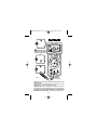
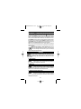
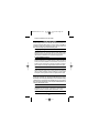
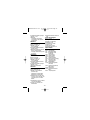
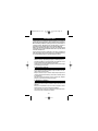
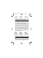
- 6 -
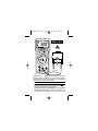
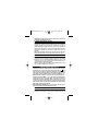
4 digit LCD with unit i ndicators
4 Di git LCD mit Einhei tsanzeigen
LCD de 4 dígitos; i ndicadores de
unidades
LCD 4 di gits; indicateurs d’uni tés
Low Battery
Pi l a b aj a
Bat t er i e ent l ad en
Pi l e d éch ar gée
Funct i o n/ Rang e Sel ec t or
Funkt i o ns - / Ber ei ch-
Schal t er
Sel ect o r de
Funci ó n/ Esc al a
Sél ect eu r f on ct i o ns /
cali bres
FUSED
MAX
40mA
MAX
mA
10A
VCOM
CAT II 10 00 V
CAT II I 6 00 V
FUSED
10A MAX
1000V
750V
OFF
V
V
A
A
MENU
RMS225A
CLEAR
SELECT
mV
AM
K
RANGE HOLD REL
0 1010 2020 3030 4040
MAX MIN
Menu bar – see “ Menu Functi ons”, page 20
Menübalken – si ehe “ Menüfunkti onen” , Seite 21
Bar r a de menú - ver “ Funci o nes de men ú” , p ági n a 21
Bar r e de menu - voi r “ Fonc t i o ns de M enu ” , p age 2 2
40-Segment Bargraf
40-Segment Bargraf
Bar r a anal ógi ca de 40
segmentos
Bar gr aphe 40- segment s
Menu Buttons (see
page 20)
Menutasten (si ehe
Sei t e 21)
Te c l as de m enú ( ver
pági na 21)
Bout ons de menu
(voir page 22)
Hi gh i n pu t f or v ol t ag e
and r esi st ance
V- Ω Ei nga ng. H och
für Spannung und
Wi de r s t a n d
Ent r a da “ al t a ” p a r a
tensión y resistencia
Ent r é e V- Ω. Haut
pour tensi on et
résistance
COM Input – commo n o r l o w i n pu t f or al l measur ement s
COM Ei n gan g – Ref er en zpunkt f ür al l e M ess un gen
COM - ent r ada común o “ b aj a” p ar a t od as l as medi das
Ent r é e C OM – commu n o u b a s pour t out e s m e sur e s
10A Input
10A Ei ngang
Ent r a da 10A
Ent r é e 10A
40mA Input
40mA Eingang
Ent r a da 40m A
Ent r é e 40m A
RMS225A.Man.07.00 11/30/00 8:30 PM Page 8

OVE R L OA D I N D I C ATI ON
Input Overload (highest range in autoranging) is
indicated by “I.OL” and a continuous tone. Remove
test leads from the measurement setup as the input
is beyond the range of the meter.
Displ ay Overl oad (input exceeds the selected
range while range is locked) is also indicated by “I.OL”. Select the next higher
range until a value is displayed, or return to autoranging. If overload still exists in
the highest range, remove test leads from the measurement setup as input is
beyond the range of the meter.
Note: In both instances, overload indication is normal in the OHMS and
continui ty ranges (no sound) when the leads are not connected to anythi ng or
when t he measu r ed v al ue i s hi gher t han t he sel ect ed r es i s tan ce r ang e.
D • Überl astanzeige
Ei n ga ngs- Übe r l a st (höchster Bereich in automatischer Bereichswahl): “I.OL”
Anzei g e u nd Dauer t on . Mes su ng unt er b r ech en d a d er M eßwer t d i e Ei ngangs gr en ze
überschreitet.
Be re i chs- Übe rl a st (Der Eingang überschreitet den betreffenden Bereich bei
manuel l er Ber ei c hs wahl - RANGE L OCK) : “ I . OL” An zei g e. Hö her en Ber ei ch wäh l en
oder Messung unterbrechen.
Anmer kung: Überl astanzei ge i st nor mal bei Wi der st andsmessung wenn
Meßkabel/ -spi tzen frei stehen oder wenn der Meßwert den Bereich überschreitet. In
al l en ander en Fäl l en i st di e Ursache der Über l ast sof or t zu ent fer nen. Höher en
Ber ei c h wäh l en od er Mes su ng un t er br ec hen .
E • I nd i c a ci ón de s ob r e ca r g a
La sobrecarga de entrada (en la escala superior en caso de selección
aut omát i ca d e esc al a) s e i n di ca med i an t e “ I . OL” y u n t o no cont i nuo. Des co nec t e l as
puntas de prueba del circuito de medida, ya que el ni vel de entrada es superi or a la
capacidad del medidor.
La sobrecarga del vi sual izador (la entrada supera la capacidad de la escala
seleccionada en modo manual) tambi én se indica mediante “I.OL” . Selecci one una
escal a más at a. Si y a est á en l a más al t a, i nt er r ump a l a med i d a.
Nota: La indicación de sobrecarga es normal, durante la medida de OHMS, cuando
el c i r c ui t o est á abi er t o o l a r esi st enci a es demas i ado al t a.
F • Indi cati on de Surcharge
Dépassement d’entrée (gamme la plus élevée en sélection automatique):
af f i c hag e d e “ I . OL” et t on c on ti nu. I n ter r ompez l a mesu re car l ’ ent r ée dép asse l a
- 7 -
RMS225A.Man.07.00 11/30/00 8:30 PM Page 9

Displ ay Symbol s
Anzei g ens ymb ol e Vi s ual i zad or - Sí mbo l o s Symbol es d’ Af f i c hag e
Danger ous vol t age war ni ng ( al so doubl e beep t one) . I nd i cat es i nput vol t ages
higher than 30 VAC and 60VDC. Gefährliche Eingangsspannung - über 30
VAC un d 6 0 VDC( au ch d op pel t er Bi ep - Ton) . Ad ver t en ci a de “ t en si ón
peli grosa” (también dobl e “bip” ). Indica tensiones de entrada superi ores a 30 VAC
y 60VDC. Indicati on de tension dangereuse - supéri eure à 30 VAC et 60VDC
(également double bip sonore).
Pol ar i ty i ndi cati on Pol ar i tätsanzei ge Indi caci ón de pol ar i dad
Indication de polarité
Low-battery voltage Batteri e entladen Pil a baja Pil e déchargée
Menu Functions - See page 20
Menu-Funkti onen - – si ehe Seite 21 Funciones de menú, ver página 21
Fonct i ons d e menu – vo i r p age 2 2
Audible Feedback
The met er emi t s a s i n gl e b eep wh en a par amet er i s c han ged , a “ val i d ” f r o nt pan el
button is pushed, or Auto Min Max or Probe Hold values are updated. A double
beep indi cates a dangerous input voltage 30 VAC and 60VDC.
The met er emi t s a c on t i n uo us t one i n t he c ase of i npu t over l oad , f or c on t i n ui t y
measur ement wh en r esi s t anc e i s <5 0Ω, and for current measurements, when the
10A input is used and the current exceeds 10A.
D • Akusti sche Anzei gen
Das Ger ät gi b t ei nen Ei nzel t on ab bei Funkt i onswechsel , bei Akt i vi er ung ei ner
“validen” Taste und wenn neue Auto Min Max- und Anzeigenspeicherwerte erfaßt
wer den. Ei n Doppel t on zei gt ei n e gef ähr l i che Ei ngangss pannung ( 30 VAC and
60VDC) an. Ein Dauerton wird abgegeben bei Eingangsüberl ast und bei
Dur chgan gs mes sun g, wenn der Wi der s t and un t er 50Ω liegt. Wenn beim RMS225A
im 10A Bereich gemessen wird, wird ein Dauerton abgegeben wenn der
Ei nga ngsst r om 10A ü be r schr e i te t .
F
E
D
F
E
D
F
E
D
F
E
D
F
E
D
capacité de l ’instrument.
Dépassement de gamme (l’entrée dépasse la gamme en sélection manuelle -
RAN GE L OC K) : i n d i c at i o n d e “ I . OL ” . Cho i s i s s e z u n e g a mme s u p é ri e u r e o u
interrompez la mesure.
Note: Une i ndi c ati on d e s ur char ge es t nor mal e dans l es c al i br es de rési st ance,
quand les pointes de touche ne sont pas connectées, ou si l a résistance mesurée
dépasse l e cali bre.
- 8 -
RMS225A.Man.07.00 11/30/00 8:30 PM Page 10

- 9 -
E • Avi sos a udi bl e s
El m e di d or e m i t e un “ b i p ” c ua ndo se ca m b i a u n pa r á m et r o , se p ul sa u na t e cl a
“válida” del panel frontal, o se actualizan los valores de Auto Min Max o Probe
Hol d . Un d obl e “ bi p” i ndi c a un a t ensi ón de ent r ada pel i gr o sa ( 30 VAC y 6 0VDC) .
El m e di d o r e m i t e u n t on o cont i n uo e n caso de sobr e ca r ga de e nt r a da , y m i d i e ndo
continui dad cuando el valor de l a resistencia es <50 Ω. Cuando se usa la entrada
de 10 A, el medidor emite un tono continuo si la corri ente supera l os 10 A.
F • Indi cati on Sonore
L’ i n s t r u m en t é met u n b i p s on or e en c as d e c h an g e me n t d e f o n ct i o n , q u a n d u n
bouton val ide est pressé ou de nouvell es valeurs Auto Mi n Max ou de mai nti en de
lecture sont enregistrées. Un double bip sonore indique la présence d’une tension
dangereuse (30 VAC et 60VDC) à l’entrée.
Un s i g nal son or e c on t i n u i nd i qu e un dép as sement de l a l i mi t e d’ ent r ée ou, l or s de
la mesure de continuité, une résistance inférieure à 50Ω. Quand, avec le RMS225A,
vous mesurez dans la gamme 10A, un signal sonore continu est émis dès que
l’entrée dépasse 10A.
Ana l og Ba r gr a p h
The anal og bar gr aph i ndi cat es whi ch per cent age of t he r ange a di spl ayed
measur ement r el at es t o . Th e zer o seg ment i s l i t when t h e i n st r umen t i s t ur n ed o n.
If the input is less than 40% of range, each segment equals 1% of range. If the
input is above 40% of range, each segment equals 10% of range. Example: a
300mV input in the 1V range (30%) is represented by 30 segments
(); a 600mV input (60%) will be represented by 6 segments
().
Exce p t i o n: in the 40mA range, one segment represents one mA.
D • Balkenanzeige
Di e Bal kenanzei ge g i bt an wel chem Prozen twer t d es Meßber ei c hes der Meßwer t
ent spr i cht . Das er s t e Segmen t l eu ch t et b ei m Ei n sc hal t en des Ger ät es auf . L i eg t d er
Ei ng a ng u n t e r 40 % d e s Me ß b e r e i chs , d a nn e n t s pr i c ht j e de s S e g m e n t 1 % d e s
Meßberei chs. Liegt der Eingang über 40% des Meßbereichs, dann entspri cht j edes
Segment 1 0% d es Meßber ei c hs . Bei spi el : Ei n Ei n gan g von 3 00 mV i m 1 V Ber ei ch
(30%) wird durch 30 Segmente angezeigt ( ); ein Eingang von 600
mV ( 60%) dur c h 6 Seg ment e ( ) .
Ausna hm e : Im 40 mA Bereich steht jedes Segment für 1 mA.
F • Barra analógi ca
La barra analógi ca indi ca el porcentaje del fondo de escala que corresponde a la
0
0 1010 2020 3030
0
0 10 20 30
RMS225A.Man.07.00 11/30/00 8:30 PM Page 11

lectura presentada en el visualizador. Al encender el instrumento se ilumina el
segmento de cero. Si la entrada es inferior al 40% del fondo de escala, cada
segmento representa el 1% de la escala. Si l a entrada es superior al 40% del fondo
de escal a, cada segmento representa el 10% de la escala. Ej emplo: una entrada de
300 mV en la escala de 1 V (30%) se representa con 30 segmentos
(); una entrada de 600 mV (60%) se representa con 6 segmentos
().
Exce pc i ó n: en l a es cal a de 40 mA, u n s egmen t o r ep r esen t a 1 mA.
F • Bargraphe Analogique
Pour chaque val eur af f i chée, l e bar gr aphe anal ogi que i ndi que l a posi t i on ( %)
correspondante dans la gamme de mesure. Le premi er segment s’affi che à l a mise
sous tension de l’appareil . Quand le si gnal d’entrée est en- dessous de 40% de l a
gamme, chaque segment correspond à 1% de la gamme. Quand le signal d’entrée
est au- dessus de 40% de l a gamme, c haque segmen t cor r espond à 10% de l a
gamme. Exemple: une entrée de 300mV dans l a gamme 1V (30%) est représentée
par 30 segments ( ); une entrée 600mV (60%) est représentée par 6
segments ( ).
Exce pt i on: Dans l a gamme 40 mA, un s egment r epr és ent e 1 mA.
0
0 1010 2020 3030
0
0 1010 2020 3030
- 10 -
MEASURING PROCEDURES
GENERAL : Tu r n i nst r umen t o n b y t u r n i n g f u nct i on/ r an g e sw i t c h awa y f r o m OFF
and s el ec t i n g t h e par amet er y ou want t o measu r e.
Rangi ng: Th i s i n st r u ment i s aut or angi ng on al l r ang es. I t aut o mat i c al l y sel ec t s
the range that gives the best resolution for the measured value. A range can be
locked through menu selection (see Menu Functions, page 20). You can tell which
range you are in by the position of the decimal point and the measurement unit
displ ayed.
Ge ne r a l M e a sur e me nt P r oce d ur e s: ■ Wh e n conn e ct i ng or di sc on ne ct i ng
test leads to a circuit, always turn off power to device or circuit being tested and
discharge all capacitors. ■ St r i ct l y obser ve the max i nput l i mi t s. ■ Do not
change functi ons whil e test leads are connected to circui t.
D • Meßprozeduren
Ei n sch al t e n: Ger ä t e i n sc ha l te n dur ch F u nkt i o ns- / B e r e i c hs sch a l t e r w e g v on OF F
nach der gewünschten Funkti on zu drehen.
Be r e i ch sw a hl : Das Ger ät wäh l t aut omat i s ch d en Ber ei c h der di e best e Auf l ö su ng
bietet. Ein Bereich kann durch Menüwahl festgehalten werden (siehe Menü-
funktionen, Seite 21). Der Dezimalpunkt und die angezeigte Einheit geben an in
wel c hem Ber ei c h Si e si c h b ef i nd en.
RMS225A.Man.07.00 11/30/00 8:30 PM Page 12

Al l ge me i n:
■
Vo r Ver b i n d en un d Tr enn en d er Meßk ab el mi t dem Sc hal t k r ei s ,
diesen abschalten und Kondensatoren entladen.
■
Maximale Grenzen nicht
überschreiten.
■
Kei n en Fu nk t i o ns wech sel v or n ehmen währ en d d i e M eßsp i t zen mi t
dem Schaltkreis verbunden si nd.
E • P r oc e di mi e nt o s d e me di da
GENERAL : Enci end a e l i n st r um e nt o, poni e ndo e l s e l ec t or de f unci ón/ es ca l a f ue r a
de OFF y seleccionando el parámetro que desee medi r.
Esca l a s : es t e i n st r u ment o sel ecci o na aut omát i c ament e l a es cal a, p on i én do se en l a
que proporciona la mejor resoluci ón para el valor que se va a medi r. Es posi ble fi jar
una escala desde el menú (vea Funciones de menú, pág. 21). La escala en que está
en u n momen t o d ado puede d et er mi n ar se po r l a p os i c i ó n del p un t o d eci mal y l as
unidades de medi da.
Procedimi entos generales:
■
Ant es de co nec t ar o des co nec t ar l as punt as de
prueba a/de un circui to, apague siempre el disposi ti vo o circui to someti do a prueba
y descargue todos l os condensadores.
■
Obse r ve e st r i c t a m e nt e l o s l ím i te s m á xi m os
de entrada.
■
No cambi e de f unci ón mi ent ras l as punt as de pr ueba est én
conectadas a un ci rcui to..
F • Procédures de Mesure
Mise sous tension: Al l umez l ’ appar ei l en to ur nant l e s él ect eur de f onct i ons à
parti r de OFF vers le paramètre à mesurer.
Sélecti on des gammes: Pour t out es l es fonct i ons, l ’apparei l choi si t
aut omat i quement l e g amme q ui o f f r e l a mei l l eu r e r éso l u t i o n. Un e gamme peu t êt r e
bloquée par sélection de menu (voi r page 22). Le point déci mal et l ’uni té affi chée
indiquent la gamme dans laquelle vous mesurez.
Gé né r a l :
■
Av an t d e c on n ec t er ou d e déc on nec t er l es c o r d on s d e t es t , co up ez
l’alimentation du circuit mesuré et déchargez les condensateurs.
■
Ne dép ass ez pas
les limites d’entrée.
■
Ne c han gez p as d e f onct i o n t an di s que l es p oi nt es de t o uc he
sont connectées au ci rcuit.
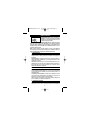
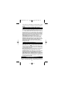
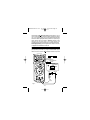
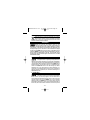
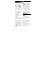
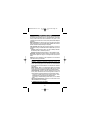
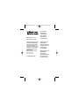
DC AND AC VOLTAGE M EASUREM ENT ( Se e F i g. 1 )
❶ Con nec t t est l ead s as s ho wn i n f i gur e 1. ❷ Tu r n f unct i o n sel ect o r sw i t c h t o V
or V . ❸ To uch Pr o b e t i p s ac r o s s vol t a g e s o u r c e ( i n pa r al l e l wi t h c i r c u i t ) . ❹
Vo l t ag e v al ue wi l l ap pear o n Di g i t al Di s p l ay al o n g wi t h t h e v o l t ag e p o l ar i t y ( f o r DC) .
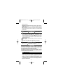
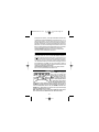
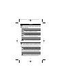
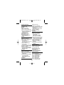
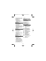
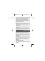
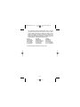
Tr u e R M S AC M e a s u r e m e n t s : M o d e l R M S 2 2 5 A i s a n AC- c o up l e d Tr u e -
RMS measuri ng meter. It measures the true RMS value of distorted AC
voltage or current signals. The Crest Factor handl ing capability is shown in
Tab l e 1. The Cr es t Fact or i s t h e Pe ak Vo l t ag e di vi d ed by t h e RM S vol t a g e.
Note: To ac c u r at el y me as u r e a DC v o l t age wi t h an AC c o mpo n en t , me as u r e t h e
AC co mpo nen t f i r st wi t h s el ec t or s wi t c h set t o V . Not e t he meas ur emen t an d
- 11 -
RMS225A.Man.07.00 11/30/00 8:30 PM Page 13

- 12 -
range used. Switch to V , activate Range Lock (see Menu Functions, page 22),
and s el ec t a r ang e equ al t o or h i g her t h en t h e V r ange us ed p r evi ou sl y. Not e t h e
measur ement . The r esul t i s t he measur ed AC Vol t age on t op of t h e measu r ed DC
component. (Max input is 1000V for any combination).
D • Glei ch- und Wechsel spannungsmessung ( Siehe Fig. 1)
❶
Meßkabel gemäß Fig.1 verbi nden.
❷
Funkt i onss ch al t er auf V or V s t el l en.
❸
Meßspitzen mit Meßkreis verbinden – parall el zur Spannungsquel le.
❹
Meßwert
abl es en ( au t omat i sch e Pol ar i t ät s anzei ge bei DC M essungen ) .
Echt - Ef f e kt i vwe rt me ssung: M ode l l RM S2 2 5A i st e i n AC- ge koppe l t e s
Echt - Ef f e kt i v we r t - me sse n de s Ge r ä t . Es mi ß t d e n ech t e n Ef f e kt i v w e r t auch v on
verzerrten Spannungs- und Stromei ngängen. Der Crest Faktor Bereich ist i n Tabell e
FUSED
MAX
40mA
MAX
mA
10A
VCOM
CAT II1 00 0V
CAT III 60 0V
FUSED
10A MAX
1000V
750V
OFF
V
V
A
A
MENU
RMS225A
CLEAR
SELECT
V
0 1010 2020 3030 4040
red/rot/
roja/rouge
2
1
3
4
V &
V
> 20V
Fig. 1
RMS225A.Man.07.00 11/30/00 8:30 PM Page 14

- 13 -
5.0
4.0
3.0
2.5
1.0
2%
0%
5%
4%
3%
100%806040200
Wave f or m, Cr est Fact or
Wel l enf or m, Cr est Fact or
Fo r m a d e o n d a, Fa c t o r d e Cr es t a
Fo r m e d ' o n d e, Fa c t e u r Cr ê t e
Addi ti onal cor rect ion f rom 1.5 to 5. 0
Zusät zli che Kor rekt ur von 1. 5 bi s 5. 0
Co r r e c c i ó n a d i t i o n al p a r a 1 . 5 a 5 . 0
Co r r e c t i o n s u p p l ém . d e 1 . 5 à 5 . 0
Input RMS, Percentage of Full-Scale • Effektiv-Wert Eingang, % vom Endbereich
Valor eficaz de entrada, % del fondo de escala • Entrée effective, % pleine échelle
Table 1
1 aufgeführt. Der Crest Faktor ist di e Spitzenspannung geteil t durch die Effektivwert-
spannung.
Anme r kun g: Um ei n e Gl ei ch sp an nun g mi t Wechsel spannu ngs ko mpon ent e r i c ht i g
zu mess en, mes sen Si e zu er st d i e Wech sel spann ung mi t d em Funk t i o ns sc hal t er au f
V. Notieren Sie den Bereich. Schalten Sie nach V, aktivieren Sie Range Lock
(siehe Menüfunktionen, Seite 22), und wählen Sie einen Bereich ebenso hoch oder
höher als der vorhin gewählte V Bereich. Noti eren Sie di e Ablesung. Das Resultat
ist die gemessene Gleichspannung mit der gemessenen Wechselspannungs-
komponente. (Max Ei ngang i st 1000V für j ede Kombinati on).
E • M e d i d a s d e t e nsi ón CC y CA ( D CV y ACV) - ( ve a F i g 1 )
❶
Conect e l a pu nt a d e pr u eba r oj a a l a ent r ada V- Ω y l a negra a la entrada COM.
❷
❷
Ponga el sel ect or d e f unci ón en Vo V. .
❸
Toq u e c on l a s p unt as de
prueba los puntos de tensión (en paralelo con el ci rcui to).
❹
Lea el valor en el
visuali zador (y la pol ari dad en caso de CC: posi ti va i mpl ícita, negati va i ndicada).
Medidas de verdadero valor eficaz en CA: El m ode l o RMS 225A e st á m e d i d or
de verdadero val or efi caz (TRMS), acopl ado en CA. Miden el verdadero valor eficaz
de señales distorsionadas de tensión o corri ente CA. En la Tabla 1 se indica la
capacidad de manejo de factores de cresta. El factor de cresta es l a tensión de pi co
divi dida por la tensión eficaz.
Nota: Par a medi r c on p r eci si ó n una t ens i ó n CC que t en ga u na compon ent e d e CA,
mi d a en pr i mer l u gar l a co mpon ent e d e CA poni en do el sel ect or de f u nc i ó n en
V .
Tome no t a de l val or m ed i do y l a es c al a ut i l i za d a. Camb i e a
V , active el bloqueo
de escala (Range Lock, Funciones de menú, pág. 22) y seleccione una escal a i gual o
superior a la uti li zada previ amente en
V . Observe la medida. El resultado es la
tensión de CA sobre la componente de CC medida. (La entrada máxima es 1000 V
RMS225A.Man.07.00 11/30/00 8:30 PM Page 15

- 14 -
para cualqui er combinación).
F• Mesure de Tensions CC et CA (voi r fi g. 1)
❶
Connect ez l e c or do n r o ug e à l ’ ent r ée V- Ω et l e n oi r à l ’ ent r ée COM.
❷
Pl ac ez l e
sélecteur sur V ou V .
❸
Connect ez l es c or d on s au ci r c ui t – en par al l èl e av ec
la source de tension.
❹
Lisez la mesure sur l’affi cheur (avec la polari té pour les
mesur es en CC) .
Mesures Efficaces Vraies: Le modèle RMS225A est un instrument à
mesure efficace vrai e avec couplage CA. Il mesure la valeur efficace vraie
égal emen t d’ ent r ées de t ensi ons et de cour ant s al t er n at i f s av ec ond e d éf or mée. L es
limites du facteur crête sont indiquées dans le tableau 1. Le facteur crête est la
valeur crête divi sée par l e valeur efficace.
Note: Pour mesur er cor r ect ement une t ensi on cont i nue avec une composant e
al t er nat i v e, mesur ez d’ abor d l a c ompo sant e al t er nat i v e avec l e sél ect eur mi s su r
V. Notez la mesure et la gamme utilisée. Placez le sélecteur sur V , activez
Ra nge L ock (v oi r F onct i ons d e M e nu, p a ge 22) , e t sé l ec t i o nne z une ga m m e é ga l e à
ou supérieure à la gamme V util isée précédemment. Notez l a mesure. Le résultat
est l a t en si on co nt i nue mes ur ée av ec l a composan t e al t er n at i v e mes ur ée. ( L’ ent r ée
max en t out e co mbi nai so n est d e 1 00 0V) .
DC AND AC CURRENT M EASUREM ENT ( Se e Fi g. 2 )
❶ Connec t r ed t est l ead t o t h e mA i nput f o r cur r ent meas ur emen t s u p t o 4 0mA o r
to the 10A input for current measurements to 10A. Connect black test lead to
COM i np ut conn ect o r. ❷ Set t h e Fu nc t i o n Swi t c h t o A or A as r equi r ed. ❸
Ope n ci r cui t i n w hi c h cu r r e n t i s t o b e m e a su r e d ( vol t a ge be t w e e n t hi s po i nt a nd
ground must not exceed 1000V). Securely connect test l eads in series with the
load. ❹ Tur n on p o wer t o ci r cui t b ei ng t es t e d. ➎ Re a d c ur r e nt v a l u e on D i gi t a l
Di s pl ay.
Note: If, in the 10A range, the meter is exposed to current greater than 10A, it
should be turned off and all owed to cool for at l east 10 minutes
Incorrect Input Warning: “FErr” is displayed when a test lead is connected to
current i nput, but the selector switch is not set to a current range.
Tr u e R M S AC M e a s u r e m e n t s : M o d e l R M S 2 2 5 A i s a n AC- c o up l e d Tr u e -
RMS measuri ng meter. It measures the true RMS value of distorted AC
voltage or current si gnals. The Crest Factor handli ng capabili ty is shown i n table
1. The Crest Factor i s the Peak Voltage divi ded by the RMS vol tage.
D • Gleich- und Wechsel strommessung (Siehe Fig. 2)
❶
Rot e s M e ß ka be l mi t de m 4 0m A Ei nga ng ve r bi n d e n f ür M e ss ung e n bi s 4 0 m A
oder mit dem 10A Ei ngang für Messungen bi s 10A. Schwarzes Meßkabel mit COM
verbinden.
❷
Funktionsschalter auf A oder A stellen.
❸
Meßkreis öffnen (an
dieser Stell e darf das Potential gegenüber Erde 1000V nicht überschreiten).
RMS225A.Man.07.00 11/30/00 8:30 PM Page 16

- 15 -
FUSED
MAX
40mA
MAX
mA
10A
VCOM
CAT II1 00 0V
CAT III 60 0V
FUSED
10A MAX
1000V
750V
OFF
V
V
A
A
MENU
RMS225A
CLEAR
SELECT
A
0 1010 2020 3030 4040
Discharge capacitors
Kondensatoren entladen
Descargue l os condensadores
Décharger les condensateurs
3b
3a
3c
4d
2
1
4
5
red/rot/
roja/rouge
A A
Fig. 2
Meßspitzen si cher i n Seri e mit dem Stromkreis verbi nden.
❹
Meßkreis einschalten.
➎
St r omwer t abl esen.
Anme r kung: We nn i m 10A Be r ei ch kur zz ei t i g ei n St r o m h öh er a l s 10A anl i e gt ,
Ge r ä t a bs cha l t e n und m i n de st e ns 10 Mi n ut e n a bkü hl en l asse n.
Ei n ga n gs wa r n un g: “FErr” wird angezeigt wenn ein Meßkabel mit einem Strom-
ei n gan g v er bu nd en i st , der Wahl s ch al t er j edoc h n i c ht au f ei n em St r omb er ei c h s t eht .
Echt - Ef f e kt i vwe rt me ssung: M ode l l RM S2 2 5A i st e i n AC- ge koppe l t e s
Echt - Ef f e kt i v we r t - me sse n de s Ge r ä t . Es mi ß t d e n ech t e n Ef f e kt i v w e r t auch v on
RMS225A.Man.07.00 11/30/00 8:30 PM Page 17

- 16 -
verzerrten Spannungs- und Stromei ngängen. Der Crest Faktor Bereich ist i n Tabell e
1 aufgeführt. Der Crest Faktor ist di e Spitzenspannung geteil t durch die Effektivwert-
spannung.
E • M e d i d a s d e cor r i e nt e CC y CA ( DCA y ACA) - ( ve a F i g. 2 )
❶
Conect e l a pu nt a de p r ueba r o j a a l a ent r ad a de 4 0mA p ar a medi d as d e c or r i ent e
hasta 40 mA, o a la entrada de 10 A para medi das de corri ente hasta 10 A. Conecte
la punta de prueba negra a la entrada COM.
❷
Ponga el s el ec t or d e f unci ó n en A
o A , según se requiera.
❸
Abr a el ci r c ui t o en el q ue vay a a medi r l a cor r i ent e. ( l a
tensión entre este punto y tierra no debe superar los 1000 V). Conecte con
seguridad las puntas de prueba, en seri e con l a carga.
❹
Conect e l a al i men t aci ón
del ci rcui to sobre el que va a medi r.
➎
Lea el valor de la corriente en el vi sual izador.
Nota: Es po s i b l e m e d i r e n t r e 1 0 y 20 A d ur a n t e u n m á x i mo d e 3 0 s e gun do s .
Después d ej e t r ansc ur r i r 10 mi n ut os par a qu e se en fr í e el i nst r ument o.
Av i s o d e e n t r a d a i n co r r e c t a : Ap ar ece “ FEr r ” c uan do se c on ect a u na p un t a de
prueba a l a entrada de corriente y el selector no está en una escal a de corriente.
Medidas de verdadero valor eficaz en CA: El m odel o RMS225 e st á me di d or
de verdadero valor efi caz (TRMS), acoplado en CA. Mide el verdadero valor eficaz de
señales di storsi onadas de tensión o corriente CA. En l a Tabla 1 se i ndica l a
capacidad de manejo de factores de cresta. El factor de cresta es l a tensión de pi co
divi dida por la tensión eficaz.
F • Mesure de Courant CC et CA (voi r fi g. 2)
❶
Connect ez l e cor don r ou ge à l ’ ent r ée 40mA p our mes ur es j usqu’ à 40 mA et à
l’entrée 10A pour mesures jusqu’à 10A. Connectez le cordon noir à l’entrée COM.
❷
Pl ac ez l e s él ec t eur s ur A ou A s el o n l a mes ur e à ef f ec t uer.
❸
Ouvr e z l e c i r cui t
à mes ur er ( l e p ot en t i el à ce po i n t par r ap po r t à l a t er r e ne do i t pas dépasser 1 00 0V) .
Connect ez l es po i nt es de t ou che so l i dement en sér i e avec l e ci r cui t .
❹
Mettez l e
circui t sous tension.
➎
Lisez l a mesure.
Note: Si , d ans l a gamme d e 10 A, vou s mesur ez b r i èv ement u n cour an t su pér i eur à
10A, éteignez l ’appareil, et l ai ssez l e refroi dir pendant an moins 10 minutes.
Av e rt i s s e m e n t d ’ En t r é e : “FErr” est affiché quand un cordon de test est relié à
une entrée de courant mai s l e sélecteur n’est pas mis sur une fonction courant..
Mesures Efficaces Vraies: Le modèle RMS225A est un instrument à
mesure efficace vrai e avec couplage CA. Il mesure la valeur efficace vraie
égal emen t d’ ent r ées de t ensi ons et de cour ant s al t er n at i f s av ec ond e d éf or mée. L es
limites du facteur crête sont indiquées dans le tableau 1. Le facteur crête est la
valeur crête divi sée par l e valeur efficace.
RESI STANCE M EASUREM ENT ( Se e Fi g. 3 )
❶ Tur n o f f a n y p o w er t o t h e r e s i s t a n c e t o b e me as u r e d a n d d i s cha r g e a n y
capacitors. Any voltage present duri ng a resistance measurement will cause
RMS225A.Man.07.00 11/30/00 8:30 PM Page 18

inaccurate readings.❷ Connect test l eads as shown i n f i gur e 3. ❸ Set
Funct i on/ Range Swi t ch t o Ω positi on. ❹ Connect t est l eads to ci r cui t bei ng
measur ed. ➎ Re a d r e s i st a n c e va l u e on D i g i t a l D i sp l a y. Ope n ci r cu i t s w i l l b e
displ ayed as “ I.OL” .
Note: Wh e n m ea s ur i n g v e r y l o w r e s i s t a n ce s , us e Re l a t i v e M e a s u r e m ent t o
el i mi nat e t h e t est l ead r es i s t anc e ( see M enu Fun ct i on s, p age 2 3) .
D • Widerstandsmessung ( siehe Fig. 3)
❶
Jede Spannung vom Wi derstand abschalten und Kondensatoren entl aden. Eine
am Wi der st and anl i egende Spannu ng wür de das Resul t at ver f äl schen.
❷
Ro t e s
Meßkabel mit V• Ω Ei ng a n g und sch w a r z e s m i t C OM v e r bi n de n.
❸
Funkt i o ns-
schalter auf Ω-Position stellen.
❹
Meßspitzen mit Widerstand/ Schaltkreis
verbinden.
➎
Meßwert ablesen. Ein offener Schal tkreis wird mit Überlast angezei gt.
- 17 -
FUSED
MAX
40mA
MAX
mA
10A
VCOM
CAT II1 00 0V
CAT III 60 0V
FUSED
10A MAX
1000V
750V
OFF
V
V
A
A
MENU
RMS225A
CLEAR
SELECT
K
0 1010 2020 3030 4040
1
4
3
5
red
rot
roja
rouge
2
Fig. 3
RMS225A.Man.07.00 11/30/00 8:30 PM Page 19

- 18 -
Anme r kun g: Bei ni edr i g en Wi der st ands wer t en mi t Rel at i vmess un g ( s i ehe Sei t e 2 3)
den Widerstand der Meßkabel kompensi eren.
E • M e d i d a s d e Re si st e n ci a ( ve a F i g . 3 )
❶
Asegúr ese de que no hay t ensi ón apl i c ada a l a r esi st enci a y des car gue l os
condensadores. La presenci a de tensión causará i mprecisi ón en las medidas de
resistencia.
❷
Conect e l a p unt a de pr ueba r oj a a l a en t r ada V- Ω y la negra a la
ent r ada COM.
❸
Ponga el sel ec t or de f u nc i ó n en l a p os i c i ó n de Ω.
❹
Conect e l as
puntas de prueba a la resistencia o circui to que vaya a medir.
➎
Lea el val or de l a
resistencia en el visualizador. Un circuito abierto se indicará como condición de
sobrecarga.
Nota: cuando esté midi endo resistencias muy bajas, util ice el modo relati vo para
el i mi n ar l a r es i s t enc i a d e l as pu nt as de p r ueb a ( vea Fu nc i o nes de men ú, p ág. 2 3. )
F • Mesure de Rési stance ( voir fi g. 3)
❶
Enl eve z t o ut e t e n si o n de l a r é si s t a nce à me su r e r e t dé c ha r ge z l es co nde n sa t e ur s .
La présence d’une tension fausserait le résultat.
❷
Connect ez l e c or don r o uge à
l’entrée V• Ω et l e no i r à l en t r ée COM.
❸
Pl ac ez l e sél ec t eur s ur l a p os i t i on Ω.
❹
Connect ez l es co rd on s au ci r c ui t à mes ur er.
➎
Lisez la valeur affi chée. Un circuit
ouvert est affiché par un dépassement de gamme.
Note: Pou r des f ai b l es v al eu r s d e r és i s t anc e, u t i l i s ez l a mes ur e r el at i v e ( v oi r page
24) pour compenser la résistance des cordons de test.
DI ODE AND CONTI NUI TY T EST ( Se e F i g . 4 )
The di od e t est measu r es t he v ol t age d r op acr os s a di od e j u nc t i o n. ❶ Co nn ect t h e
test leads as shown in figure 4. ❷ Set t he Fun ct i on / r an ge swi t ch t o . ❸
Appl y pr o be t i p of r ed l ead t o t he an od e an d of bl ac k l ead t o t h e cat hod e o f t he
diode. ❹ The met er ’ s di sp l ay i nd i c at es t he f o r war d vo l t ag e dr op ( ap pr o x. 0. 6 V f or
sil icon diode or 0.4V for germanium diode). An open diode i s indi cated by “ I OL” .
➎ Re v e r se t e s t l e a d conne ct i ons t o t he di ode t o pe r f or m a r e ve r se bi as t e s t . “ I OL”
indicates a good diode. Not e s: “I OL” for both reverse and forward bias tests
indicates an open diode. A low voltage reading for both bias tests indicates a
shorted di ode. If the di ode is shunted by a resistor of 1000 ohms or less, i t must
be removed from the circuit before taking the measurement. Bipolar transistor
junctions may be tested in the same manner described above as emitter-base and
base-col lector j uncti ons are diode junctions.
When measuri ng conti nui ty (also for shorted diodes) the meter emits a
continuous tone when the resi stance value fall s below 50Ω.
D • Dioden- und Transistortest
Der Di o dent est zei gt den Spannungsabf al l über den Di odendur chgan g
❶
Rot e s
Meßkabel mit V-Ω Ei n g a n g u n d s c h w ar z es mi t COM Ei n ga n g v e r b i n d e n .
❷
Hz
A
V
A
%
V
RMS225A.Man.07.00 11/30/00 8:30 PM Page 20
Seite laden ...
Seite laden ...
Seite laden ...
Seite laden ...
Seite laden ...
Seite laden ...
Seite laden ...
Seite laden ...
Seite laden ...
Seite laden ...
Seite laden ...
Seite laden ...
Seite laden ...
Seite laden ...
Seite laden ...
Seite laden ...
Seite laden ...
Seite laden ...
Seite laden ...
Seite laden ...
Seite laden ...
Seite laden ...
Seite laden ...
-
 1
1
-
 2
2
-
 3
3
-
 4
4
-
 5
5
-
 6
6
-
 7
7
-
 8
8
-
 9
9
-
 10
10
-
 11
11
-
 12
12
-
 13
13
-
 14
14
-
 15
15
-
 16
16
-
 17
17
-
 18
18
-
 19
19
-
 20
20
-
 21
21
-
 22
22
-
 23
23
-
 24
24
-
 25
25
-
 26
26
-
 27
27
-
 28
28
-
 29
29
-
 30
30
-
 31
31
-
 32
32
-
 33
33
-
 34
34
-
 35
35
-
 36
36
-
 37
37
-
 38
38
-
 39
39
-
 40
40
-
 41
41
-
 42
42
-
 43
43


Wavetek 225A Bedienungsanleitung
- Kategorie
- Multimeter
- Typ
- Bedienungsanleitung
- Dieses Handbuch ist auch geeignet für
in anderen Sprachen
- English: Wavetek 225A Operating instructions
- français: Wavetek 225A Mode d'emploi
- español: Wavetek 225A Instrucciones de operación
Verwandte Papiere
-
Wavetek RMS225A Bedienungsanleitung
-
-
Wavetek AC40A AD40A Bedienungsanleitung
-
-
 Wavetek Meterman 160B Benutzerhandbuch
-
-
-
Wavetek AD105 Bedienungsanleitung
-
-


