Wavetek 2020/2030 Bedienungsanleitung
- Kategorie
- Multimeter
- Typ
- Bedienungsanleitung
Dieses Handbuch eignet sich auch für

OP E R AT O R ’S MA N U A L
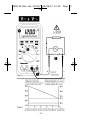
2020/2030
Autoranging Digital
M u l t i m e t e r s
BE D I E N U N G S A N L E I T U N G
MA N U A L D E IN S T R U C C I O N E S
MA N U E L D’ UT I L I S AT I O N
2020/30.Man.3x5,25/XPr 19/06/97 14:35 Page 1

WARRANTY
The 2020 and 2030 Digital Multimeters are warranted against any defects of
material or workmanship within a period of one (1) year following the date of
purchase of the multimeter by the original purchaser or original user.
Any multimeter claimed to be defective during the warranty period should be
returned with proof of purchase to an authorized Wavetek Corp. Service Center
or to the local Wavetek dealer or distributor where your multimeter was
purchased. See maintenance section for details.
Any implied warranties arising out of the sale of a Wavetek multimeter,
including but not limited to implied warranties of merchantability and fitness for
a particular purpose, are limited in duration to the above stated one (1) year
period. Wavetek shall not be liable for loss of use of the multimeter or other
incidental or consequential damages, expenses, or economical loss or for any
claim or claims for such damage, expenses or economical loss.
Some states do not allow limitations on how long implied warranties last or
the exclusion or limitation of incidental or consequential damages, so the
above limitations or exclusions may not apply to you.
This warranty gives you specific legal rights, and you may also have other
rights which vary from state to state.
D GEWÄHRLEISTUNG
Auf die Digitalen Multimeter Modelle 2020 und 2030 gibt Wavetek ein Jahr
Gewährleistung ab Kaufdatum auf Material- und Herstellungsfehler. Siehe für
Einzelheiten Kapitel “Unterhalt und Reparatur”.
Für weiterführende Ansprüche aus Garantiefällen, wie Folgeschäden,
Gewinnausfälle usw. kommt Wavetek nicht auf.
E GARANTIA
Los Multímetros Digitales Modelos 2020 y 2030 están garantizados contra
cualquier defecto de material o de mano de obra durante un periodo de un (1) año
contado a partir de la fecha de adquisición. En la sección de “Mantenimiento y
Reparación” se explican los detalles relativos a reparaciones en garantía.
Cualquier otra garantía implícita está también limitada al periodo citado de un (1)
año. Wavetek no se hará responsable de pérdidas de uso del multímetro, ni de
ningún otro daño accidental o consecuencial, gastos o pérdidas económicas, en
ninguna reclamación a que pudiera haber lugar por dichos daños, gastos o pérdidas
económicas.
F GARANTIE
Les multimètres digitaux, Modèles 2020 et 2030 sont garantis pour un (1) an
à partir de la date d’achat contre les défauts de matériaux et de fabrication. Voir
chapitre “Maintenance et Réparation” pour plus de détails.
Toute garantie impliquée est également limitée à un an. Wavetek ne peut être
tenu responsable pour perte d’utilisation ou autres préjudices indirects, frais,
perte de bénéfice, etc.
2020/30.Man.3x5,25/XPr 19/06/97 14:35 Page 2

CONTENTS
D • Inhalt
E • Contenidos
F • Contenu
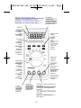
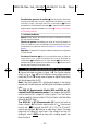
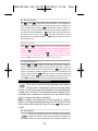
EPLANATION OF SYMBOLS
D • Erklärung der Symbole = E • Significado de los símbolos = F • Explication des Symboles
Safety Information ............................................... 2
Instrument Familiarization.................................... 4
Measurement Procedures ................................... 9
Menu Functions................................................. 22
Specifications ................................................... 28
Maintenance and Repair .................................... 40
Sicherheitsinformationen .................................... 2
Vorstellung des Gerätes....................................... 4
Meßprozeduren ................................................... 9
Menü Funktionen............................................... 23
Spezifikationen .................................................. 30
Unterhalt und Reparatur .....................................41
Información de seguridad ................................... 3
Familiarización con el instrumento......................4
Procedimientos de medida .................................. 9
Menu Functions................................................. 23
Especificaciones ............................................... 35
Mantenimiento y reparación .............................. 41
Informations de Sécurité ..................................... 3
Présentation de l’Appareil ................................... 4
Procédures de Mesure ...................................... 10
Fonctions de Menu............................................ 23
Spécifications ................................................... 39
Maintenance et Réparation ................................ 41
Attention! Refer to Operating Instructions •D• Achtung! Bitte Anleitung
lesen •E• ¡Atención! Consulte las Instrucciones de Uso •F• Attention!
Consultez le manuel.
Ground connection •D• Erdanschluß •E• Conexión a tierra
•F• Connection de terre.
Alernating current •D• Wechselstrom •E• Corriente alterna
•F• Courant alternatif.
Direct current •D• Gleichstrom •E• Corriente continua
•F• Courant continu.
Dangerous voltage may be present at terminals •D• Eine gefährliche
Spannung kann an den Eingängen anliegen •E• Puede haber tensión
peligrosa en los terminales •F• Une tension dangereuse peut être
présente aux entrées.
This instrument has double insulation •D• Dieses Gerät ist doppelt
geisoliert•E• Este instrumento tiene doble aislamiento •F• Cet
appareil est prévu d’une double isolation.
– 1 –
2020/30.Man.3x5,25/XPr 19/06/97 14:35 Page 3
Seite wird geladen ...
Seite wird geladen ...
Seite wird geladen ...
Seite wird geladen ...
Seite wird geladen ...
Seite wird geladen ...
Seite wird geladen ...
Seite wird geladen ...
Seite wird geladen ...
Seite wird geladen ...

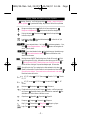
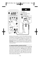
D • Gleich- und Wechselspannungsmessung (siehe Fig.1)
❶ Meßkabel wie in Figur 1 gezeigt verbinden. ❷ Funktionsschalter auf V oder
V stellen. ❸ Meßspitzen mit Meßkreis verbinden – parallel zur
Spannungsquelle. ❹ Meßwert ablesen (automatische Polaritätsanzeige bei DC
Messungen).
Anmerkung: Wenn der Eingang 25V überschreitet, erscheint ein Blitz-Symbol in
der Anzeige zusammen mit einem doppelten Biepton, um anzugeben daß die
Eingangsspannung lebensgefährlich sein kann.
Echt-Effektivwertmessungen: Modelle 2020 und 2030 sind AC
gekoppelte Echt-Effektivwert-messende Geräte. Sie messen den echten
Effektivwert, auch von verzerrten Strom- und Spannungs-Wellenformen. Der
Crest-Faktorbereich wird in Tabelle 1 gezeigt. Der Crest Faktor ist der Spitzenwert
geteilt durch den Effektivwert.
Echt Effektivwert (AC + DC) Messungen: ❶ Meßkabel wie in Figur 1 gezeigt
verbinden. ❷ Funktionsschalter auf V stellen. Zweite Funktionstaste
drücken um Echt-Effektivwertmessung (AC + DC) zu aktivieren. AC und DC
Symbole werden angezeigt. ❸ Wie unter Punkt 3 oben weiter messen. Das Gerät
sperrt den Bereich gemäß höchstem Eingangssignal. Steigt die Spannung über
diesen Bereich hinaus (OL Anzeige), höheren Bereich mit
✔RNG Menüfunktion
wählen (Siehe Menüfunktionen, Seite xx).
E • Medidas de tensión CC y CA (vea Fig. 1)
❶
Conecte las puntas de prueba como se muestra en la Figura 1.
❷
Ponga el
selector de función en ACV o DCV.
❸
Toque con las puntas de prueba los puntos
de tensión (en paralelo con el circuito).
❹
Aparece el valor de la tensión en el
visualizador digital, junto con la polaridad en l caso de DCV.
Note: If the input exceeds 25V, a lightning bolt appears in the display, coupled
with a double beep tone, indicating that the voltage is potentially lethal.
Medidas de verdadero valor eficaz en CA: Los modelos 2020 y 2030 son
medidores de verdadero valor eficaz (TRMS), acoplados en CA. Miden el
verdadero valor eficaz de señales distorsionadas de tensión o corriente CA. En la
Tabla 1 se indica la capacidad de manejo de factores de cresta. El factor de cresta
es la tensión de pico dividida por la tensión eficaz.
True RMS (AC + DC) Measurements: ❶ Connect test leads as shown in
figure 1. ❷ Turn function selector switch to V . Press second function key
to activate true RMS (AC + DC). The AC
and DC symbols are displayed. ❸ Continue as under step 3 above. The meter
range locks for highest AC signal input. If the voltage is too high (OL displayed),
select
✔RNGand up range until a reading appears (see Menu Functions).
F • Mesure de Tensions CC et CA (voir fig. 1)
❶ Connectez les câbles comme indiqué en figure 1. ❷ Placez le sélecteur sur
VDC ( ) ou VAC ( ). ❸ Connectez les pointes de touche au circuit – en
parallèle avec la source de tension. ❹ Lisez la valeur.
– 12 –
2020/30.Man.3x5,25/XPr 19/06/97 14:36 Page 14
Seite wird geladen ...

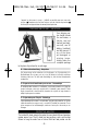
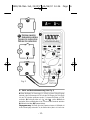
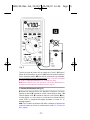
D • Gleich- und Wechselstrommessung (siehe Fig. 2)
❶ Rotes Meßkabel für Messungen bis 100mA mit dem 100mA Eingang
verbinden, oder für Messungen bis 10A mit dem 10A Eingang (bis 20A können
bis max 30 Sekunden gemessen werden). Schwarzes Meßkabel mit COM
verbinden. ❷ Funktionsschalter auf A oder A stellen. ❸ M e ß k r e i s
abschalten, öffnen und Meßspitzen sicher in Serie mit dem Stromkreis verbinden.
❹ Meßkreis einschalten. ➎Stromwert ablesen.
Eingangswarnung: Das Gerät gibt einen Dauerton ab wenn ein Meßkabel mit
einem Stromeingang verbunden ist, der Wahlschalter jedoch nicht auf einer
– 14 –
Fig. 2
2020/30.Man.3x5,25/XPr 19/06/97 14:36 Page 16
Seite wird geladen ...

pointes de touche solidement en série avec le circuit. ❹ Mettez le circuit sous
tension. ➎Lisez la mesure.
Avertissement d’entrée: Un signal sonore vous avertit quand un cordon de
mesure est connecté à une entrée de courant, alors que le sélecteur ne se trouve
pas sur une fonction de courant. Une telle mesure endommagerait l’appareil.
“FErr” est affiché.
Mesure efficace vraie: Les modèles 2020 et 2030 sont des
instruments à mesure efficace vraie avec couplage CA. Ils mesurent la
valeur efficace vraie également de formes d’onde déformées en tension et en
courant CA. La figure 1 montre l’évolution du facteur crête. Le facteur crête est la
valeur crête divisée par la valeur efficace.
Mesure Efficace Vraie (CA + CC): ❶ Connectez les câbles comme indiqué
en figure 1. ❷ Placez le sélecteur sur A . Pressez la seconde touche de
fonction pour activer la mesure efficace vraie (CA + CC). Les symboles AC
(CA) et DC (CC) sont affichés. ❸ Continuez comme sous le point 3 plus haut.
L’instrument bloque la gamme correspondante à la plus haute valeur d’entrée. Si,
par la suite, la valeur d’entrée excède cette gamme (OL affiché), choisissez une
gamme plus élevée avec la fonction
✔RNG du menu (voir Fonctions de Menu,
page xx). Changez éventuellement de l’entrée 100mA vers l’entrée 10A (en
déconnectant d’abord l’appareil).
RESISTANCE MEASUREMENT (See Fig. 3)
❶ Turn off any power to the resistance to be measured and discharge any
capacitors. Any voltage present during a resistance measurement will
cause inaccurate readings.❷ Connect test leads as shown in figure 3. ❸
Set Function/Range Switch to Ω position. ❹ Connect test leads to circuit
being measured. ➎ Read resistance value on Digital Display. Open
circuits will be displayed as “OPEN” in autoranging mode and as “OL” in
Range-Lock mode.
Note: When measuring very low resistances, use Relative Measurement
to eliminate the test lead resistance (see Menu Functions).
D • Widerstandsmessung (siehe Fig. 3)
❶ Stellen Sie sicher daß keine Spannung am Widerstand oder Meßkreis anliegt.
Eine Spannung würde die Messung verfälschen. ❷ Meßkabel wie in Figur 3
verbinden. ❸ Funktionsschalter auf Ω Position stellen. ❹ Meßspitzen mit
Schaltkreis verbinden. ➎ Meßwert ablesen. Offene Schaltungen oder zu hohe
Widerstände werden bei automatischer Bereichswahl als “OPEN” und mit
Bereichssperre als “OL” angezeigt.
Anmerkung: Beim Messen sehr niedriger Widerstände, Widerstand der
Meßkabel durch Relativmessung ausgleichen (siehe Menüfunktionen, Seite xx).
E • Medidas de resistencia (vea Fig. 3)
❶ Asegúrese de que no hay tensión aplicada a la resistencia o al circuito. ❷
– 16 –
2020/30.Man.3x5,25/XPr 19/06/97 14:36 Page 18
Seite wird geladen ...
Seite wird geladen ...
Seite wird geladen ...
Seite wird geladen ...
Seite wird geladen ...
Seite wird geladen ...

D • Menü-Funktionen
D i e - oder - Taste aktiviert den Menübalken in der Anzeige und
verschiebt den Cursor (Unter-Strich) nach links oder nach rechts. Mit dem Cursor
unter der gewünschten Funktion, - Taste drücken um diese Funktion zu
aktivieren. Ein ✔-Symbol wird auf der linken Seite der Funktion angezeigt. Um
eine aktive Funktion zu desaktivieren - Taste drücken wenn de Cursor unter
der gewünschten Funktion steht. - Taste zwei mal drücken um alle
Menüfunktionen zu desaktivieren. A n m e r k u n g : Mehrere Funktionen können
gleichzeitig aktiv sein.
E • Menu Functions
Either or key engages the menu bar in the display and moves the
cursor (underline) left or right. While the cursor is under the desired function,
press the key to activate that function. A check mark appears to its left. To
desactivate an active function, press the key while the function is selected
on the menu bar (underlined). Press key twice to deselect all menu
functions. Note: Several menu functions can be active concurrently.
F • Fonctions de Menu
La touche ou engage la barre de menu sur l’afficheur et déplace le
curseur (soulignement) vers la gauche ou vers la droite. Tandis que le curseur se
trouve en-dessous d’une fonction, pressez la touche pour activer cette
fonction. Le symbole ✔ apparait à la gauche de la fonction. Pour désactiver une
fonction, pressez la touche tandis que le curseur se trouve en-dessous de
cette fonction. Pressez deux fois pour désactiver toutes les fonctions de
menu. Note: Plusieurs fonctions de menu peuvent être actives simultanément.
READING HOLD
Works with all functions except capacitance and frequency.
Allows to take a measurement and then remove the probes
from the circuit while the value remains displayed. A tone indicates when
a stable value is recorded. The measurement remains displayed until a
new stable input is measured, an overload occurs, the function selector
switch is changed or the meter is powered off.
N o t e : To suppress false triggering, the minimum range for voltage is
preset to 10V range and measurements less than 800 counts will not be
held. In order to select ranges less than 10V, press when cursor is
on HLD.
D • Anzeigesperre
Steht für alle Meßfunktionen zur Verfügung, ausgenommen
Kapazität und Frequenz. Nach der Messung bleibt der Meßwert auf
der Anzeige erhalten, auch wenn die Meßspitzen vom Schaltkreis getrennt sind.
– 23 –
2020/30.Man.3x5,25/XPr 19/06/97 14:36 Page 25
Seite wird geladen ...

E • Medidas Relativas
Works with all functions. Teniendo una medida en el visualizador,
activate the REL function. Memorizándose la lectura presente como
valor de referencia y reponiéndose el visualizador a cero. Para las medidas
subsiguientes, el visualizador indica la diferencia entre el nuevo valor y el
almacenado como referencia.
F • Mesure Relative
Est disponible pour toutes les fonctions de mesure. Avec une mesure
sur l’afficheur, activez la fonction REL. La valeur affichée est prise comme
référence, et l’affichage est mis à zéro. Pour les prochaines mesures, cette valeur-
référence est déduite du résultat, et seule la différence est affichée.
AUTO MIN MAX
TM
(MX-MN AV)
Works in all functions. Measures and records the
minimum, maximum and running average of both
positive and negative polarity input signals. Select measurement function
and apply input to meter before activating MX-MN AV. The meter
continues to display the current reading while recording min and max
values. Each new recording is indicated with a beep tone. Press to
sequentially see max (MX displayed), min (MN displayed), max - min
(MX-MN displayed), average (AV displayed) and current values (MX MN
AV displayed). To reset the recording, desactivate and reactivate the MX-
MN AV function. Auto-power-down is desactivated with MX-MN AV.
D • Auto Min/Max Messung (MX-MN AV)
Steht für alle Meßfunktionen zur Verfügung. Mißt und
speichert Minimum, Maximum und laufende Mittel-Werte von
positiven und negativen Eingangssignalen. Meßfunktion wählen und Eingang
anlegen bevor Sie MX-MN AV aktivieren. Das Gerät zeigt laufende Werte an und
speichert gleichzeitig Min und Max Werte. Jede neue Speicherung wird mit einem
Biebton befestigt. Taste drücken um nacheinander Max Werte (MX
angezeigt), Min Werte (MN angezeigt), Max minus Min Werte (MX-MN
angezeigt), laufende Mittelwerte (AV angezeigt) und laufende Werte (MX-MN AV
angezeigt) anzuzeigen. Funktion aus- und wieder einschalten um mit neuen
Meßwerten zu beginnen. Automatische Abschaltung steht mit aktiver MX-MN AV
Funktion nicht zur Verfügung.
E • Medidas Auto Min/Max (MX-MN AV)
Works in all functions. Measures and records the
minimum, maximum and running average of both positive and
negative polarity input signals. Select measurement function and apply input to
meter before activating MX-MN AV. The meter continues to display the current
– 25 –
2020/30.Man.3x5,25/XPr 19/06/97 14:36 Page 27

reading while recording min and max values. Each new recording is indicated with
a beep tone. Press to sequentially see max (MX displayed), min (MN
displayed), max - min (MX-MN displayed), average (AV displayed) and current
values (MX MN AV displayed). To reset the recording, desactivate and reactivate
the MX-MN AV function. Auto-power-down is desactivated with MX-MN AV.
F • Mesure Auto Min/Max (MX-MN AV)
Disponible pour toutes les fonctions de mesure. Mesure et
affiche les valeurs courantes tout en enregistrant les valeurs
maximales, minimales et moyennes d’entrées positives et négatives.Choisissez
une fonction de mesure et appliquez un signal d’entrée avant d’activer MX-MN AV.
L’appareil continue à afficher les valeurs courantes et enregistre les valeurs
minimales et maximales. Chaque nouvel enregistrement est confirmé par un bip
sonore. Pressez pour afficher séquentiellement les valeurs maximales (MX
affiché), les valeurs minimales (MN affiché) les valeurs max - min (MX-MN
affiché), les valeurs moyennes, (AV affiché) et les valeurs courantes (MX MN AV
affiché). Désactivez et réactivez la fonction MX-MN AV pour enregistrer de
nouvelles valeurs. La coupure automatiques est désactivée avec MX-MN AV.
PEAK HOLD (PK)
Works with AC and DC current and voltage and records inputs as
short as 1ms. Select measurement function and apply input to
meter before activating PK. Measurement of positive peak values begins
immediately. To measure peak negative values (MIN), move cursor to MX-
MN AV and press so MN appears. Measurement of peak negative
values begins immediately. Two tones indicate a new value has been
recorded. Press the second function button to reset Peak Hold to accept
new peak readings. Auto-power-down is desactivated with PK.
Note: Peak Hold measurement locks the current range. See Range Lock
(RNG) to change range.
D • Spitzenwertspeicher (PK)
Steht für AC und DC Strom- und Spannungsmessungen zur Verfügung
und speichert Signale bis zu 1ms. Meßfunktion wählen und Eingang
anlegen bevor Sie PK aktivieren. Damit beginnt die Speicherung von positiven
Spitzenwerten. Um negative Spitzenwerte zu speichern, Menü aktivieren und
Cursor nach MX-MN AV bringen. Taste drücken bis MN angezeigt wird.
Damit werden negative Werte gespeichert. Ein doppelter Biepton befestigt die
Speicherung eines neuen Wertes. Die zweite Funktionstaste drücken um Speicher
zu löschen und mit der Speicherung neuer Werte zu beginnen. Automatische
Abschaltung steht mit aktiver PK Funktion nicht zur Verfügung.
A n m e r k u n g : Spitzenwertspeicherung blokiert den anstehenden Bereich. Siehe
Bereichssperre (RNG) um einen anderen Bereich zu wählen.
– 26 –
2020/30.Man.3x5,25/XPr 19/06/97 14:36 Page 28
Seite wird geladen ...
Seite wird geladen ...

D • Automatische Abschaltung
Um die Batterie zu schonen schaltet das Gerät nach 30 Minuten Inaktivität
automatisch ab. Sie können es wieder einschalten durch die zweite Funktionstaste
zu drücken oder den Funktionsschalter nach OFF und zurück nach einer
Meßfunktion zu drehen.
E • Apagado Automatico
El multímetro se apaga automáticamente cuando transcurren 30 minutos sin
a c t i v i d a d . You can turn it back on by simply pressing the second function key
, or by turning the function selector switch to OFF and back to a measuring
function.
F • Coupure Automatique
Afin d’économiser les piles, l’instrument s’éteint automatiquement après 30
minutes d’inactivité. Vous pouvez le ralummer en pressant la deuxième touche de
fonction ou en tournant le sélecteur de fonctions sur OFF et à nouveau sur
une fonction de mesure
INCORRECT INPUT WARNING
A continuous tone warns you warns you when a test lead is placed in the
10A input jack and the Selector switch is not set to current. (If the DMM is
connected to a voltage source with leads set for current, very high current
could result). All current ranges are protected with fast acting fuses.
D • Eingangswarnung
Ein akustisches Signal warnt Sie wenn ein Meßkabel mit dem 10A Stromeingang
verbunden ist, der Funktionsschalter jedoch nicht auf Strom steht. Eine solche
Messung würde einen sehr hohen Strom im Gerät verursachen. Alle
Stromeingänge sind mit flinken Sicherungen geschützt.
E • Aviso por Conexion Incorrecta de las Puntas de Prueba
El zumbador suena si ha conectado una punta de prueba a la entrada de corriente
10A y el selector no está en una escala de corriente. De seguir adelante con la
medida podría dañar el multímetro. All current ranges are protected with fast
acting fuses.
F • Avertissement d’Entrée
Un signal sonore vous avertit quand un cordon de mesure est connecté à l’entrée
10A alors que le sélecteur n’est pas placé sur une gamme de courant. Une telle
mesure endommagerait l’appareil. Toutes les gammes de courant sont protégées
par des fusibles rapides.
– 29 –
2020/30.Man.3x5,25/XPr 19/06/97 14:36 Page 31
Seite wird geladen ...
Seite wird geladen ...
Seite wird geladen ...

Allgemeine Spezifikationen
Anzeige: 5 Digit LCD, 18888 Punkte, 41-
Segment Bargraf, Menübalken,
Funktions- und Einheitsanzeigen.
Polaritätsanzeige: Automatisch.
Nullabgleich: Automatisch
Überlastanzeige: OL
Entladene Batterieanzeige: bei 7.5V.
Es bleiben etwa 20 Stunden.
Automatische Abschaltung bei 6.6V.
Anzeigenauffrischung: 2/Sek, nominal;
20/Sek für Bargraf.
Betriebstemp.: 0 bis 50°C, 0 bis 80%
Relative Feuchte
Lagertemp: -40°C bis 70°C, 0 bis 95%
R.F., Batterie entfernt.
Temperaturkoeffizient: <0.1 x
(angegebene Genauigkeit)/°C (0° bis
20°C und 30° bis 55°C)
Stromversorgung: Standard 9-Volt
Transistorbatterie, NEDA 1604, JIS
006P, IEC 6F22
Automatische Abschaltung: Nach 30
Minuten Inaktivität.
Autonomie (typisch): 200 Stunden
Alkaline
Abmess. (H x B x T): 175 x 90 x 34 mm
Gewicht mit Batterie: 568 g
Zubehör: Meßkabel, Ersatzsicherung,
Batterie, Anleitung
Schock und Vibration: MIL-T-28800,
Klasse II
Gehäusematerial: Feuerwehrendes,
stoßbeständiges Thermoplastik
Sicherheit: Gemäß EN61010-1:
1993/A2:1995 Kat III, UL3111, IP44.
EMC Dieses Produkt beant-
wortet an die Bestimmungen
der folgenden EWG Richtlinien:
89/336/EEC (Elektromagnetische Kompa-
tibilität) und 73/23/EEC (Niedrige
Spannung) geändert durch 93/68/EEC
(CE Marking).
Elektrisches Rauschen und starke
magnetische Felder in der direkten
Umgebung des Meßgerätes können
jedoch den Meßkreis beeinflussen. Das
Gerät kann auch durch Störsignale im ge-
messenen Schaltkreis beeinflußt werden.
Der Anwender muß Vorsichtsmaßnahmen
treffen um irreführende Meßergebnisse
bei Messungen in der Umgebung von
starken elektromagnetischen Feldern zu
vermeiden.
Elektrische Spezifikationen
Genauigkeit bei 23°C ± 5°C, <75% R.F.
für ein Jahr gewährleistet.
Gleichspannung
Bereiche:
100, 1000mV, 10, 100, 1000V
Auflösung, 0.01mV im 100mV Ber.
Genauigkeit, alle Bereiche: 2020:
±(0.25%vMW +2Dgt)
2030: ±(0.10%vMW +2Dgt)
Eingangsimpedanz: 10MΩ
Ansprechzeit: <2s
NMRR: >60dB bei 50 oder 60Hz
CMRR: >120dB bis 1000Vdc
Überlastschutz: 1000VDC oder AC
Spitze. 6kV Transienten.
Gefährliche Spannungsanzeige: Blitz-
Symbol in der Anzeige und doppelter
Biepton wenn Eingangsspannung 25V
überschreitet.
Wechselspannung.
Genauigkeiten für Eingänge von 5% bis
Endbereich.
Bereiche: 100, 1000mV, 10, 100, 1000V
Auflösung: 0.01mV im 100mV Bereich
Genauigk.
2.0% vMW ±8Dgt bei 45 bis
2kHz (bis 400Hz im 100mV Bereich)
Ansprechzeit: <3s
Frequenzverhalten: 3dB >10kHz
Eingangsimpedanz: 10MΩ // <100pF
AC Umsetzung: Echt-effektiv, AC
gekuppelt; Echt-effekiv (AC+DC) in
V Funktion durch Drücken der
zweiten Funktionstaste (selbe AC
Spezifikationen wie Wechselspannung
plus ±2% Gleich-
spannungsgenauigkeit in allen
Bereichen. Bei hoher Gleichspannung
muß mit gesperrtem Bereich gemessen
werden um ein richtiges Resultat zu
erhalten.)
Crest Faktor: 1:1 bis 5:1
Überlastschutz: <10Hz: 400Vrms; >10Hz:
1000Vrms. 6kV Transienten.
– 33 –
D SPEZIFIKATIONEN
2020/30.Man.3x5,25/XPr 19/06/97 14:36 Page 35

Gleichstrom
Bereiche: 1000µA, 10, 100, 1000mA, 10,
20A
Auflösung, 0.1µA im 1000µA Bereich
Bereich Genauigk. Genauigk.
2020 2030
1000.0µA 1.0%±2Dgt 0.5%±2Dgt
10.000mA 0.5%±1Dgt 0.35%±1Dgt
100.00mA 0.5%±1Dgt 0.35%±1Dgt
1000.0mA 1.0%±2Dgt 0.5%±1Dgt
10.000A 1.0%±1Dgt 1.0%±1Dgt
20.00A 1.0%±1Dgt 1.0%±1Dgt
Spannungsabfall, 1000µA bis 100mA
Bereiche: 15mV/mA; 1000mA bis 20A
Bereiche: 40mV/A
Ansprechzeit: <3s
Überlastschutz: mA Eingang: 0.25A/600V
Sicherung; 1000A Trennvermögen
A Eingang: 10A kontinuierlich, 20A für
30 Sekunden. 15A/600V Sicherung.
100kA Trennvermögen.
Wechselstrom (45-1000Hz)
Bereiche: 1000µA, 10, 100, 1000mA, 10,
20A
Auflösung, 0.1µA im 1000µA Bereich
Genauigkeit, 1000µA bis 1000mA
Bereiche: ±(1.7%vMW + 8Dgt)
10, 20A Bereiche: ±(1.7%vMW ±3Dgt)
Spannungsabfall: siehe Gleichstrom
Ansprechzeit: <3s
Frequenzverhalten: 3dB >10kHz
AC Umsetzung: Echt-effektiv AC
gekoppelt; Echt effektiv (AC+DC) in
A Funktion durch Drücken der
zweiten Funktionstaste (gleiche
Spezifikationen wie Wechselstrom).
Crest Faktor: 1:1 bis 5:1
Überlastschutz: siehe Gleichstrom
Widerstand
Bereich Genauigk. Genauigk.
2020 2030
100.00Ω 0.7%±4Dgt 0.5%±4Dgt
1000.0Ω 0.5%±4Dgt 0.3%±4Dgt
10.000kΩ 0.5%±4Dgt 0.3%±4Dgt
100.00kΩ 0.5%±4Dgt 0.3%±4Dgt
1000.0kΩ 0.5%±4Dgt 0.3%±4Dgt
10.000MΩ 1.5%±4Dgt 0.7%±4Dgt
20.00MΩ 2.0%±4Dgt 1.2%±4Dgt
Max Teststrom: 1.0mA im 100Ω Ber.; 0.1
mA im 1000Ω Ber.; 10µA im 10kΩ
Ber.; 1.0µA im 100kΩ Ber.; 0.1µA in
anderen Bereichen.
Max Testspannung: 100mV in 100Ω bis
1000kΩ Bereichen; 1.0V im 10MΩ
Bereich; 2.0V im 20MΩ Bereich.
Auflösung, 0.01Ω im 100Ω Ber.
Ansprechzeit: <2s unter 1MΩ; <3s über
1MΩ
Max Leerlaufspannung: 6.5V
Überlastschutz, alle Bereiche: 500VDC
oder AC effektiv.
Dioden/Durchgangstest
Bereich: 2V
Aulösung: 0.2mV
Teststrom: 1.0mA max
Anzeige: Spannungsabfall über
Diodendurchgang
Ansprecheit: <2s
Genauigkeit: ±(1.0%vMW +5Dgt)
Leerlaufspannung: 5.5VDC
Ansprechzeit, Durchgangstest: <200ms
Schwelle, Durchgangstest: <200mV
Durchgangsanzeige: Dauerton bei R
≤100Ω.
Anzeige, offene Schaltung: “OPEN”
Überlastschutz: 500VDC oder AC effektiv
Kapazität
Bereiche: 20, 200nF, 2, 20, 200µF; 2mF
Auflösung, 100pF im 20nF Bereich
Genauigkeit, 20, 200nF Bereiche:
2.0%vMW ± 3Dgt; 2, 20µF Bereiche:
2.0%vMW ±2Dgt; 200µF Bereich:
3.0%vMW ±3Dgt; 2mF Bereich:
3.0%vMW ±8Dgt
Ansprechzeit (nach erster Auffrischung):
<1s unter 20µF; <2s unter 200µF;
<25s bis 2mF
Max Leerlaufspannung: 6.5V
Überlastanzeige: “OL” in automatischer
Bereichswahl und bei gesperrtem
Bereich bei zu hohem Kapazitätswert
oder kurzgeschlossenen Meßkabeln;
“OPEN” bei gesperrtem Bereich und
Kapazitätswert unter 10% des
Bereiches (ausgenommen 20nF
Bereich: Nullanzeige)
Überlastschutz: 500VDC oder AC effektiv
Frequenzzähler
Bereiche: 19.999, 199.99kHz,
1.9999MHz
Auflösung, 1.0Hz im 19.999kHz Ber.
Genauigkeit, 19.999kHz Bereich:
±(0.2%vMW +2Dgt)
– 34 –
2020/30.Man.3x5,25/XPr 19/06/97 14:36 Page 36

Empfindlichkeit: 100mV in 19.999 und
199.99kHz Bereichen; 1.0V im
1.9999MHz Bereich
Ansprechzeit: <1.5s
Eingangsimpedanz: 51kΩ in Dioden, AC
gekoppelt
Überlastschutz: 300VDC oder AC effektiv
Bargraf: steht nicht zur Verfügung
Taktverhältnis
Frequenzbereiche: 40 bis 1000Hz, 1k bis
20kHz, 20 bis 100kHz
Prozent des Bereiches: 5 bis 95%
Auflösung: 0.1%
Genauigkeit,
40 bis 1000Hz: 2.0% vMW ±1Dgt
1k bis 20kHz: 1.0% vMW ±1Dgt
20 bis 100kHz: 5.0% vMW ±1Dgt
Ansprechzeit: <1.5 s
Eingangsimpedanz: 51kΩ in Dioden, AC
gekoppelt
Überlastschutz: 300VDC oder AC eff.
Bargraf: steht nicht zur Verfügung
Impulserfassung
Anzeige: 50ms Ton bei positiven
Übergängen. Dauerton bei Impulsrate
über 20Hz.
Erfassung: AC gekoppelt
Logikpegel: TTL, CMOS
Schwelle: 2.6V
Min Impulsbreite: 50ns
Max Ansteiggeschwindikeit: 10ns
Impulsrate: 1MPPS
Eingangsimpedanz: 10MΩ // 150pF
Optionszubehör
RF241 650MHz Hochfrequenzsonde
DL243B Standard Testkabelsatz
DL248B Deluxe Testkabelsatz
TC 253 Temperaturumsetzer
(900°C/1652°F)
TL245 Ersatz-Sicherheitsmeßkabel
CT231 150A Wechselstromzange
CT232 1000A Wechselstromzange
CT234A 400A Wechselstromzange
CT235 1000A AC/DC Stromzange
CT236 500A Wechselstromzange (mV
Ausgang)
CT237 200A AC/DC Stromzange
CT238 20A AC/DC Stromzange
FPC850 KIT : Fiber Optic Meßsatz
VC221 Gefütterte Vyniltasche. Für Meter
und Holster
VC231 Gefütterte Vyniltasche. Für Meter
ohne Holster
– 35 –
E ESPECIFICACIONES
Especificaciones Generales
Visualizador: LCD de 5 dígitos, 18888
cuentas, barra analógica de 41
segmentos, indicadores de función y
unidades
Indicación de polaridad: Automática
Ajuste de cero: Automático
Indicación de sobrecarga: OL
Indicación de “pila baja”: at 7.5V –
20 hours left. Low-battery-cut-off at
6.6V.
Frecuencia de refresco de la lectura: 2
veces/segundo nominal; 20 veces/s la
barra analógica.
Temp. de funcionamiento: 0 a 50 °C, 0 a
80% H.R.
Temp. de almacenamiento: -40 a 70 °C, 0
a 95% H.R., sin pila.
Coef. de temperatura: 0.1 x (precisión
espec.)/°C (0° a 20°C y 30° a 55°C)
Alimentación: Pila normal de 9 V, NEDA
1604, JIS 006P, IEC 6F22
Apagado automático: El medidor se
apaga transcurridos 30 minutos sin
actividad
Duración de la pila (típica): alcalina 200
hrs
Dimensiones: 175 x 90 x 34 mm
Peso (pila incluida): 568 g
Accesorios: Puntas de prueba, fusible de
repuesto, pila y Manual de
Instrucciones
Shock and vibration: MIL-T-28800, class
II
Case material: Flame retardant, high-
impact thermoplastic
Seguridad: Según normas EN61010-1:
1993/A2:1995 Cat III, UL3111, IP44.
EMC: Este producto cumple
los requisitos de las siguientes
Directivas de la Comunidad
Europea: 86/336/EEC (Compatibilidad
2020/30.Man.3x5,25/XPr 19/06/97 14:36 Page 37
Seite wird geladen ...
Seite wird geladen ...
Seite wird geladen ...
Seite wird geladen ...
Seite wird geladen ...
Seite wird geladen ...

Ampere fuse holder. Replace with Wavetek ref FG3000-400-214, Little
Fuse ref. KLK-15 or Bussman ref. KTK-15. B a t t e ry Replacement:
Remove battery and replace with NEDA type 1604 or equivalent 9-volt
alkaline battery. Reassemble the instrument.
Warning: Use only an equivalent fuse to the one specified. Use of an
incorrect fuse could result in serious injury or even death.
Warning: Failure to turn off the multimeter before installing the battery
could result in damage to the instrument and to the battery if the battery is
connected incorrectly to the multimeter.
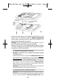
D • Batterie/Sicherungsaustausch (siehe Fig 7)
Wa r n u n g : Um elektrischen Schock zu vermeiden, Gerät vor Öffnen abschalten
und Meßkabel entfernen
Geräterückseite losschrauben und abheben. mA Eingangssicherung: D e f e k t e
Sicherung entfernen und mit 0.25A/600V flinker Sicherung ersetzen (Teil Nummer
FP250; 4er Packung). 10/20A Eingangssicherung: Defekte 1 5 A / 6 0 0 V
Sicherung entfernen und mit gleichwertiger ersetzen (Wavetek ref FG3000-400-
214, Little Fuse ref. KLK-15 or Bussman ref. KTK-15). B a t t e r i e a u s t a u s c h :
Batterie entfernen und durch gleichwertige 9V Batterie (NEDA 1604) ersetzen.
Geräterückseite wieder anbringen und festschrauben.
Warnungen: Nur gleichwertige Sicherungen verwenden. Nicht-Abschalten des
Gerätes bei Batterieaustausch kann Batterie und Gerät zerstören.
E • Sustitución de la Pila y los Fusibles (vea fig. 7)
Advertencia: Para evitar el peligro de descarga eléctrica, apague el multímetro y
desconecte las puntas de prueba antes de abrir la tapa posterior. Quite los tres
tornillos y levante la tapa posterior. Fusible de la entrada de mA: retire el
– 42–
Fig. 7
2020/30.Man.3x5,25/XPr 19/06/97 14:36 Page 44
Seite wird geladen ...

9045 Balboa Ave. Hurricane Way
San Diego, CA 92123 Norwich, NR6 6JB, U.K.
Tel: (619) 279 2200 Tel: int + 44-1603-404824
Fax: (619) 627 0130 Fax: int + 44-603-483670
The DMM will be returned with the transportation charges paid by Wa v e t e k
Corporation.
D • Reparatur
Lesen Sie die Gewährleistung bevor Sie eine Reparatur unter oder außerhalb
Gewährleistung anfragen. Unter Gewährleistung bringen Sie bitte das defekte
Gerät zu einer anerkannten Wavetek Verkaufsstelle oder Servicestelle für einen
direkten Umtausch. Außerhalb Gewährleistung senden Sie das Gerät zu einer
Wavetek anerkannten Servicestelle. Bitte informieren Sie sich bei Wavetek oder
ihrem Fachhändler nach der nächst beiliegenden Adresse und nach aktuellen
Reparaturgebühren.
Bitte senden Sie folgende Informationen und Dokumente mit: Firmenname,
Kundenname, Adresse, Te l e f o n n u m m e r, Kaufnachweis (für Reparaturen unter
Gewährleistung), eine kurze Beschreibung der gewünschten Handlung, und die
geforderte Bezahlung (Eingriffe außerhalb der Gewährleistung). Bitte auch
Testkabel beifügen.
Bezahlungen in Form eines Checks, Bezahlungsformulieren, Kredietkarte mit
Verfalldatum, usw. bitte in Namen der Servicestelle aufstellen. Bitte Multimeter
(Frei) senden an:
U.S.A. und Canada: Europa:
Wavetek Corporation Wavetek Ltd
Instrument Repair Instrument Repair
9045 Balboa Ave. Hurricane Way
San Diego, CA 92123 Norwich, NR6 6JB, U.K.
Tel: (619) 279 2200 Tel: int + 44-1603-404824
Fax: (619) 627 0130 Fax: int + 44-603-483670
oder an die Ihnen mitgeteilte Adresse. Multimeter wird (Frei) zurück geschickt.
E • Reparación
Lea las condiciones de garantía, al principio de este manual, antes de solicitar
cualquier reparación dentro o fuera de garantía. Si la reparación es en garantía,
puede llevar el multímetro defectuoso a cualquier Distribuidor Autorizado o Centro
de Servicio de Wavetek, donde le cambiarán en mano el producto por otro igual o
similar. Para reparaciones fuera de garantía deberá enviar el multímetro a un Centro
de Servicio de Wavetek. En Wavetek, o en su Distribuidor o punto de venta, le
indicarán el Centro de Servicio más próximo y las tarifas de reparación vigentes.
La documentación que acompañe a todo multímetro enviado para reparación debe
incluir los siguientes datos: nombre de la empresa, persona de contacto, dirección,
número de teléfono, prueba de compra (para reparaciones en garantía), una breve
– 44 –
2020/30.Man.3x5,25/XPr 19/06/97 14:36 Page 46
Seite wird geladen ...
Seite wird geladen ...
-
 1
1
-
 2
2
-
 3
3
-
 4
4
-
 5
5
-
 6
6
-
 7
7
-
 8
8
-
 9
9
-
 10
10
-
 11
11
-
 12
12
-
 13
13
-
 14
14
-
 15
15
-
 16
16
-
 17
17
-
 18
18
-
 19
19
-
 20
20
-
 21
21
-
 22
22
-
 23
23
-
 24
24
-
 25
25
-
 26
26
-
 27
27
-
 28
28
-
 29
29
-
 30
30
-
 31
31
-
 32
32
-
 33
33
-
 34
34
-
 35
35
-
 36
36
-
 37
37
-
 38
38
-
 39
39
-
 40
40
-
 41
41
-
 42
42
-
 43
43
-
 44
44
-
 45
45
-
 46
46
-
 47
47
-
 48
48


Wavetek 2020/2030 Bedienungsanleitung
- Kategorie
- Multimeter
- Typ
- Bedienungsanleitung
- Dieses Handbuch eignet sich auch für
in anderen Sprachen
- English: Wavetek 2020/2030 Operating instructions
- français: Wavetek 2020/2030 Mode d'emploi
- español: Wavetek 2020/2030 Instrucciones de operación
Verwandte Artikel
-
Wavetek 2015 Bedienungsanleitung
-
-
-
 Wavetek Meterman 160B Benutzerhandbuch
-
-
-
 Wavetek Meterman 235 Bedienungsanleitung
-
 Wavetek Meterman AM8 Bedienungsanleitung
-
 Wavetek Meterman DM78A Benutzerhandbuch
-
 Wavetek Meterman Meterman 220 Benutzerhandbuch


Andere Dokumente
-
 Chauvin-Arnoux CA5230G Bedienungsanleitung
-
CHAUVIN ARNOUX f 65 Benutzerhandbuch
-
Facom 711 Bedienungsanleitung
-
Megger DCM1500 Benutzerhandbuch
-
Beta 1760DGT Bedienungsanleitung
-
Tektronix DMM916 Instructions For Use Manual
-
Megger DLRO-10 Benutzerhandbuch
-
CHAUVIN ARNOUX CA5003 Benutzerhandbuch
-
Amprobe DM78B Digital Multimeter Benutzerhandbuch
-
TACKLIFE DM02A Bedienungsanleitung
