Lunos Nexxt built-In device Installationsanleitung
- Typ
- Installationsanleitung

1
DE Einbauanleitung
Dezentrales Lüftungssystem
mit Wärmerückgewinnung
Typ Nexxt
Einschub
- Bitte an den Nutzer weiterleiten -
EN Installation Manual
Decentralised Ventilation
System with Heat Recovery
Type Nexxt
Slide-in unit
- Please pass on to user -

2
(C)
15 cm
30 cm
1
(A)
(B)
2 3
4 5
9/NXT-IBF 40105
9/NXT-IB 40146
NXT-E 40130
NXT 41192

3
(E)
7
8
(Z1)
(Z2)
(Z3)
(Z4)
(Q)
(P)
(N)
(O)
9
10
6
(D)
(D)
(D)

4
(Z6)
(Z5)
Silvento ec Silvento ec Silvento ec
(Z7)
(Z8)
11
12

5
(G)
(F)
13
(H)
14
15
(I)
16
(F)
17

6
Diese Anleitung beschreibt die Aufputzmontage und Unterputzmontage der dezentralen Lüftungs-
geräte mit Wärmerückgewinnung Typ Nexxt
Lesen Sie vor Montage diese Anleitung sorgfältig und vollständig durch! Beachten Sie unbedingt
die allgemeinen Sicherheitshinweise und die Sicherheitssymbole mit Hinweisen im Text.
Diese Anleitung ist nach Abschluss der Montage an den Nutzer (Mieter, Eigentümer, Hausverwal-
tung usw.) weiterzugeben.
Zeichen in dieser Anleitung
Vorsicht! Jede Montagearbeit am Lüftungsgerät darf nur bei allpolig abgetrennter Netz-
spannung erfolgen!
Achtung! Der elektrische Anschluss darf nur von autorisiertem Fachpersonal und nach
gültiger VDE 0100 vorgenommen werden!
Achtung! Dieses Gerät darf nicht von Kindern und Personen (Filterwechsel/Reinigung)
bedient werden, die aufgrund ihrer physischen, sensorischen oder geistigen Fähigkeiten oder
ihrer Unerfahrenheit oder Unkenntnis nicht in der Lage sind, es sicher zu bedienen. Kinder
sollten beaufsichtigt werden, um sicherzustellen, dass sie nicht mit dem Gerät spielen.
Entsorgen Sie die Verpackung sortenrein. Wenn Sie sich vom Gerät trennen möchten, ent-
sorgen Sie es zu den aktuellen Bestimmungen. Auskunft erteilt die kommunale Stelle.
Dieses Zeichen warnt Sie vor Verletzungsgefahren.
Dieses Zeichen warnt Sie vor Verletzungsgefahr durch Elektrizität.
Gerätespannung: 200-240 V AC 50/60 Hz
Steuerspannung: 1 -10 V DC SELV
Elektrische Leistungsaufnahme: 5,7-40/46,5 W
Schutzart: IP 22
Volumenstrom: 15-75 m³/h
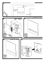
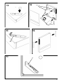
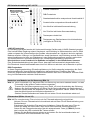
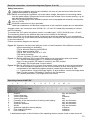
Montieren Sie das Lüftungsgerät mit einem empfohlenen seitlichen Mindestabstand von 30 cm und
einem empfohlenen Mindestabstand nach oben und nach unten von 15 cm.
Der seitliche Abstand dient zur Gewährleistung der Lüftungsfunktion, der Abstand nach oben und
nach unten der Montagefreiheit.
Wir empfehlen, das Gerät in einer Höhe von 1,50 m einzubauen, damit eine nutzerfreundliche Bedie-
nung gewährleistet ist.
(C) Fenster
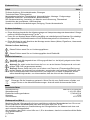
Zu dieser Anleitung, Sicherheitshinweise, Entsorgen 6
Technische Daten, Einbauposition, 6
Montagebesonderheiten, Einsatzbereich, Versandeinheiten, Montage - Fertigmontage 7
Elektrischer Anschluss - Anschlussbilder, Bedienelement 8
DIP-Schaltereinstellung, Anstecken von Modulen an die Steuerung, Filterwechsel 9
Verschließen der Innenblende, USB-Anschluss 10
Hinweis zu LUNOS-Außenabdeckungen, Reinigung, Zusatz-/Austauschteile 10
Einbauanleitung DE
Zu dieser Anleitung
Inhalt Seite:
Technische Daten
Einbauposition (Bild 1)
Entsorgen
Sicherheitshinweise

7
Temperatureinsatzbereich: - 15°C bis + 40°C
Einsetzbar bei einer relativen Luftfeuchte bis 65% im Innenraumbereich (nicht kondensierend). Bei
Überschreitung der Einsatzgrenzen Gerät ausschalten und Innenblende verschließen. Frischluftzu-
fuhr durch Fensterlüftung sicherstellen.
Entsteht Kondensat, wird dieses automatisch nach außen abgeführt. Achten Sie bitte im Winter da-
rauf, dass es zu keiner Eisbildung am Außengitter und im Bereich darum kommt.
Das Lüftungsgerät muss im Innenraum lotrecht an einer Außenwand installiert werden.
Es ist nur eine Einbaulage möglich und zwar mit oben befindlichen nach rechts und links
zeigenden Luftöffnungen.
Das Lüftungsgerät muss für Betrieb und Wartung immer frei zugänglich sein, die Luftöffnun-
gen dürfen nicht zugebaut, verstellt oder abgedeckt werden
Stellen Sie bei nachträglicher Montage sicher, dass im Bereich des Mauerdurchbruchs keine
Versorgungsleitungen (z.B. Gas, Wasser, Strom) liegen
Stellen Sie sicher, dass der Mauerdurchbruch den statischen Erfordernissen vor Ort ent-
spricht, ziehen Sie ggf. einen Sturz ein.
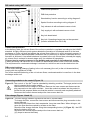
Überprüfen Sie die Lieferung auf Vollständigkeit und einwandfreien Zustand!
Bild 2: Einschub mit Enthalpiewärmetauscher Typ NXT und NXT-E
(A) Deckel mit Sichtrahmen; (B) Einschub
+ Filter, Magnetverschlüsse und Schraubenzubehör
Bild 3: Innenblende Typ 9/NXT-IBF
Bild 4: Innenblende Typ 9/NXT-IB
Bild 5: Setzen Sie den Einschub in das Wandeinbaugehäuse ein.
Hinweis: Der Einschub muss sich genau in das passive Übergangsstück (elektrischer Klap-
penverschluss) und auf die Netzanschlussplatine fügen.
Durch das Einsetzen wird der elektrische Anschluss des Einschubes realisiert.
Bitte achten Sie auf einen korrekten Sitz der Dichtung des passiven Übergangsstückes
(elektrischen Klappenverschlusses)!
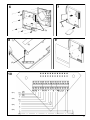
Bild 6: Setzen Sie den Gehäusedeckel auf das Wandeinbaugehäuse mit dem darin befindli-
chen Einschub auf!
Führen Sie das Flachbandkabel (D) bei NXT-E durch die Öffnung im Gehäusedeckel! (D)
Schrauben Sie den Gehäusedeckel mit den beiliegenden Schrauben am Wandeinbaugehäu-
se fest.
Bild 7: Setzen Sie die Filter ein.
Achten Sie auf die korrekte Anströmrichtung der Filter, sie ist durch einen Pfeil markiert.
(D) Flachbandkabel (nicht bei NXT)
Bild 8: Schließen Sie das Bedienelement der Innenblende an die Steuereinheit des Einschubs
an.
Hinweis: Dieser Montageschritt entfällt bei Verwendung der Innenblende Typ 9/NXT-IB.
(E) Innenblende Typ 9/NXT-IBF
Bild 9: Setzen Sie die Innenblende auf, sie wird durch Magnete in den vier Befestigungspunkten
gehalten.
Fertig!
Montagebesonderheiten
Versandeinheiten (Bilder 2 bis 4)
Montage - Fertigmontage (Bilder 5 bis 9)
Einsatzbereich

8
Vorsicht! Jede Montagearbeit am Lüftungsgerät darf nur bei allpolig abgetrennter Netzspan-
nung erfolgen!
Machen Sie vor Anschluss des Lüftungsgerätes an die Netzspannung alle Anschlussleitungen
spannungsfrei! (Abtrennung vom Netz mit mindestens 3 mm Kontaktöffnung, z.B. allpolig tren-
nende elektr. Sicherung).
Jeder zu diesem Lüftungssystem gehörende Stromkreis muss mit einem Fehlerstromschutz
(z.B. FI-Schalter) ausgestattet sein!
Elektrischer Anschluss nur durch Fachmann!
Sicherheitshinweise
Verwenden Sie als Netzkabel maximal NYM-J 5 x 1,5 mm²! Der Anschluss des PE-Leiters ist unbe-
dingt notwendig!
Zur Anbindung der TAC und/oder der Gestensteuerung benutzen Sie Kabel des Typs J-Y(St)Y
(2x2x0,8), max. 1,5 mm²! Die Anschlusslitzen für den elektrischen Klappenverschluss sind werkssei-
tig beigelegt!
Netzanschlussleiterplatte und Netzanschlussklemmen sind zur Unterstützung beschriftet!
Keinesfalls eines der schon an die Netzanschlussplatine werksseitig angeschlossenen Kabel lösen!
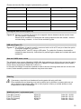
Weitere Anschlussbilder auf Anfrage!
Bild 10: Betrieb über das Bedienelement am Gerät und Darstellung der verschiedenen An-
schlussmöglichkeiten je nach Verfügbarkeit
(Z1) zum elektrischen Klappenverschluss 9/KVEN-2
(Z2) zur Gestensteuerung 5/GS
(Z3) zur TAC, KNX Control 4 bzw. 0 -10 V
(Z4) Netzanschluss
((N) rot; (O) schwarz; (P) weiß; (Q) gelb)
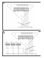
Bild 11: Manuelles Schalten der Volumenstromstufen über einen externen zweipoligen Taster:
L1 = Volumenstromstufe größer; L2 = Volumenstromstufe kleiner
Hinweis: DIP-Schalter 2 muss hierfür in Position OFF sein.
((Z5) Brücke; (Z6) 2-Wippentaster zweipolig)
Bild 12: Manuelles Schalten der Volumenstromstufen über einen externen einpoligen Taster
an L1 und gleichzeitigem Betrieb von einem oder mehreren Abluftventilatoren über Kopp-
lung an L2 zum Ausgleich des durch die Abluftventilatoren entstehenden zusätzlichen Un-
terdrucks.
L1: 1x Tasten: Volumenstromstufe grösser; 2x Tasten: Volumenstromstufe kleiner
Hinweis: DIP-Schalter 2 muss hierfür in Position ON sein.
((Z7) Schalter zweipolig; (Z8) Taster einpolig)
1 2 3 4 5 6 7 8 9 10 11
1 EIN/AUS Taste und Anzeige
2 Volumenstrom kleiner Taste
3 Volumenstromstufe Anzeige
4 Volumenstrom größer Taste
5 Möglichkeit der Abschaltung der Tastenhinterleuchtung Taste und Anzeige
6 Sommerschaltung Taste und Anzeige
7 Automatikbetrieb Taste und Anzeige
8 WLAN Taste und Anzeige
9 Warnanzeige Frostschutzbetrieb Anzeige
10 Filterwechselanzeige Anzeige
11 Fehleranzeige Anzeige
Eine detaillierte Beschreibung der Funktionen des Bedienelements finden Sie auf www.lunos.de.
Bedienelement 9/NXT-IBF
Elektrischer Anschluss - Anschlussbilder (Bilder 10 bis 12)

9
Werkseinstellung:
Weißer DIP-
Schalter
LUNOS Frostschutz
Im Auslieferungszustand werden die Volumenströme des Gerätes nach LUNOS-Standard geregelt.
Eine hocheffiziente Regelung erkennt Kondensat- und Eisbildung im Wärmetauscher oder im Gerät
selbst und passt die Volumenströme des Gerätes vollautomatisch an. Hierdurch wird eine optimale
Balance zwischen Lüftungs- und Geräteeffizienz sowie Kondensat- und Eisbildung erreicht. Bei kriti-
schen Konditionen wird eine sog. Disbalance in den Gerätevolumenströmen erzeugt, wodurch der
Zuluftvolumenstrom in mehreren Stufen bis zur vollständigen Abschaltung reduziert wird.
Hierdurch kann es zu Unterdruck im Gebäude und speziell in den Ablufträumen kommen.
Eine Sicherheitsabschaltung kann dazu führen, dass das Gerät automatisch abgeschaltet wird.
Die Erfordernis eines Kondensatabflusses ist auf ein Minimum reduziert und ist bauseits zu prüfen.
DIBt Frostschutz
In dieser Regelungseinstellung (Einstellungsänderung im Gerät notwendig) entsprechen die Gerä-
teeigenschaften den Vorschriften der allgemeinen bauaufsichtlichen Zulassung des DIBt.
Durch die eingeschränkt balancierten Gerätevolumenströme kann es zu Kondensat- und/oder Eisbil-
dung im Wärmetauscher und/oder Gerät kommen.
1 2 3 4
Bild 13: Durch Anstecken von Modulen kann die Steuerung des Nexxt erweitert werden. Für das
Funkmodul ist die größere Tasche rechts vorgesehen.
Trennen Sie die Spannungsversorgung vom Gerät, z.B. durch Ausschalten der Sicherung.
Nehmen Sie die Innenblende ab und lösen Sie die Steckverbindung zum Bedienelement.
Stecken Sie das Modul wie abgebildet in die dafür vorgesehene Tasche. Achten Sie darauf,
dass das Modul korrekt und komplett aufgesteckt ist.
Stecken Sie das Bedienelement wieder an und setzen Sie die Innenblende wieder auf.
Bild 14: Ein verschmutzter Filter wird durch die Filterwechselanzeige signalisiert.
Nehmen Sie zum Filterwechsel die Innenblende ab und lösen Sie die Steckverbindung zum
Bedienelement.
Entnehmen Sie die beiden Filter aus ihren Aufnahmen. Setzen Sie zwei neue Filter ein.
Achten Sie dabei auf die auf den Filtern durch Pfeile markierte Strömungsrichtung.
Setzen Sie die Filterwechselanzeige über die entsprechende Taste ((H) Bild 15) zurück -
das Leuchten der LED unterhalb des Tasters erlischt.
Stecken Sie das Bedienelement wieder an und setzen Sie die Innenblende wieder auf.
((G) Schlaufen zum Herausnehmen der Filter)
Filterwechsel (Bilder 14 und 15)
DIP-Schaltereinstellung NXT / NXT-E
Anstecken von Modulen an die Steuerung (Bild 13)
Tastensperre deaktiviert
Nur Zuluft bei aktivierter Sommerschaltung
Sonderfunktion entsprechend Anschlussbild 3
Standardtasterfunktion entsprechend Anschlussbild 2
DIBt Frostschutz
LUNOS Frostschutz
Nur Abluft bei aktivierterSommerschaltung
Tastensperrung, Bedienelement ist nicht bedienbar
(verfügbar ab FW 0.98)

10
Bitte notieren Sie hier die von Ihnen durchgeführten Filterwechsel:
Filterwechsel-Datum Voraussichtlicher Filterwechsel Eingesetzter Filtertyp
Bild 156 Bei nicht vorhandenem elektrischen Klappenverschluss kann mit den magnetischen
Verschlusselementen im Bedarfsfall die Innenblende verschlossen werden:
Lüftungsgerät ausschalten und Verschlusselemente mit der roten Seite nach außen von
außen vor die Lüftungsgitter legen.
Bild 17: Der USB-Anschluss (I) kann zur Kommunikation mit einem PC verwendet werden und es
besteht die Möglichkeit von Programm-Updates für Ihren Nexxt.
Verbinden Sie Nexxt und PC mit einem USB-Kabel. Zur Aktualisierung der Firmware laden
Sie die Update-Datei herunter (www.lunos.de). Die Anleitung für die Durchführung des Up-
dates liegt jeder Update-Datei bei.
Filter M5 (2 Stück) 9/FNXT-5 Bestell-Nr.: 40109
Filter F7 (2 Stück) 9/FNXT-7 Bestell-Nr.: 40110
Filter F9 (2 Stück) 9/FNXT-9 Bestell-Nr.: 40111
Funkmodul FM-EO Bestell-Nr.: 40083
Wischen Sie bei Bedarf Innenfassade und Gehäuseteile mit einem trockenen weichen Tuch
ab.
Filterwechsel und Reinigung dürfen nicht von Kindern und Personen durchgeführt werden, die
aufgrund ihrer physischen, sensorischen oder geistigen Fähigkeiten oder ihrer Unerfahrenheit
oder Unkenntnis nicht in der Lage sind, diese sicher durchzuführen.
Die von LUNOS angebotenen Außenabdeckungen aus Vollkunststoff bieten eine hohe Schlagregen-
festigkeit und können in der Beanspruchungsgruppe III nach DIN 4108-3 (2014-11) eingesetzt wer-
den. Metallische oder metallisch beschichtete Abdeckungen können in der Beanspruchungsgruppe I
nach DIN 4108-3 (2014-11) eingesetzt werden.
Bei Gebäuden in windexponierten Lagen oder der Gefahr von Starkwinden und Regen auf die Au-
ßenabdeckungen sind ggf. weitere Wetterschutzmaßnahmen zu treffen.
Zusatz-/Austauschteile
Hinweis zu LUNOS-Außenabdeckungen
USB-Anschluss (Bild 17)
Verschließen der Innenblende (Bild 16)
Reinigung

11
These instructions describe surface mounting and flush mounting of the decentralised ventilation
units with heat recovery type Nexxt.
Read this manual carefully and completely prior to installation! Always observe the general safety
instructions and the safety symbols with information in the text.
Hand out this manual to the user (tenants, proprietors, property management etc.) after comple-
ting assembly.
Symbols in this manual:
Caution! Any installation work on the ventilation unit may only be carried out with the
mains voltage disconnected at all poles!
Attention! The electric connection may only be made by authorised qualified personnel
and according to the applicable version of VDE 0100!
Attention! This unit must not be operated (filter change/cleaning) by children or persons
who are not capable of operating it safely due to their physical, sensory or mental abilities or
their lack of experience or knowledge. Children should be supervised to ensure that they do not
play with the unit.
This symbol warns you against risks of injury
This symbol warns you against risks of injury from electricity
Dispose of the packaging correctly sorted. If you wish to dispose of the device, please follow
the current regulations. Information is available from your local authority.
Unit voltage: 200-240 V AC 50/60 Hz
Control voltage: 1 -10 V DC SELV
Electrical power consumption: 5.7-40/46.5 W
Protection class: IP 22
Volume flow: 15-75 m³/h
Mount the ventilation device with a recommended lateral minimum separation distance of 30 cm and
a recommended minimum separation distance of 15 cm above and below.
The side separation distance serves to ensure the ventilation function, the separation distance above
and below the assembly freedom.
We recommend to install the device at an altitude of 1,50 meters to ensure a user-friendly operating.
(C) window
About this manual, Safety instructions, Disposal 11
Technical data, Installation position 11
Special installation features, Range of application 12
Shipping units, Installation-Final assembly 12
Electrical connection-Connection diagrams, Operating element 13
DIP-switch setting, Connecting modules to the control, Filter change 14
Closing the innner screen, USB port, Note on LUNOS outer covers 15
Cleaning, Additional parts / replacement parts 15
Installation Manual EN
Installation position (Figure 1)
Contents Page:
About this manual
Technical data
Safety instructions
Disposal

12
Indoors, the ventilation unit must be installed vertically on an outer wall.
There is only one installation position possible - with the air openings at the top pointing to
the right and left.
The ventilation unit must always be freely accessible for operation and maintenance; the air
openings must not be blocked or covered.
In case of subsequent installation, make sure that there are no supply lines (e.g. gas, water,
electricity) in the area of the wall breakthrough
Make sure that the wall breakthrough corresponds to the static requirements on site, if neces-
sary install a lintel.
Temperature application range: - 15°C to + 40°C
Can be used at a relative humidity of up to 65% indoors (non-condensing). The user is requested to
switch off the unit and close the inner screen if the application limits are exceeded. Ensure a supply
of fresh air by window ventilation.
If condensate is produced, it is automatically discharged to the outside. In winter, please ensure that
there is no ice formation on the outer grille and in the area around it.
Please check the delivery for completeness and mint condition!
Figure 2: Built-in device with crossflow heat exchanger type NXT and NXT-E
(A) cover with view frame; (B) built-in device
+ filter, magnetic closures and screw accessories
Figure 3: Inner screen type 9/NXT-IBF
Figure 4: Inner screen type 9/NXT-IB
Figure 5: Insert the built-in device into the wall installation housing.
Note: The built-in device must fit exactly into the passive transition piece (electrical flap
closure) and onto the mains connection board.
The electrical connection of the built-in device is made by inserting it.
Please ensure that the seal of the passive transition piece (electrical flap closure) is cor-
rectly seated!
Figure 6: Place the housing cover on the wall installation housing with the built-in device in it!
Lead the flat ribbon cable (D) at the NXT-E through the opening in the housing cover!
Screw the housing cover to the wall installation housing using the screws provided.
Figure 7: Insert the filters.
Make sure that the inflow direction of the filters is correct - it is marked by an arrow.
(D) ribbon cable (Not NXT)
Figure 8: Connect the control element of the inner screen to the control unit of the built-in device.
Note: This step is not necessary when using the inner screen type 9/NXT-IB.
(E) inner screen type 9/NXT-IBF
Figure 9: Put on the inner screen - it is held by magnets in the four fixing points.
Done!
Shipping units (Figures 2 to 4)
Range of application
Special installation features
Installation - Final assembly (Figures 5 to 9)

13
Caution! Any installation work on the ventilation unit may only be carried out with the mains
voltage disconnected at all poles!
Before connecting the ventilation unit to the mains voltage, disconnect all connecting cables
from the power supply! (Disconnect from the mains with at least 3 mm contact opening, e.g. all-
pole disconnecting electrical fuse).
Each circuit belonging to this ventilation system must be equipped with residual current protec-
tion (e.g. RCD)!
Electrical connection only by a specialist!
Additional installations and electrical components in this ventilation system are not admissible!
Safety instructions
As power cable, use a maximum size of NYM-J 5 x 1.5 mm²! It is absolutely necessary to connect
the PE conductor!
To connect the TAC and/or the gesture control, use cable type J-Y(St)Y (2x2x0.8), max. 1.5 mm²!
The connecting wires for the electrical flap closure are included in the delivery!
Mains connection circuit board and mains connection terminals are labelled for your convenience!
Never disconnect any of the cables that have already been connected to the mains connection board
by the manufacturer!
Further connection diagrams on request!
Figure 10: Operation via the control element on the unit and illustration of the different connection
options depending on availability
(Z1) for electrical flap closure 9/KVEN-2
(Z2) for gesture control 5/GS
(Z3) for TAC, KNX Control 4 or 0 -10 V
(Z4) mains connection
((N) red; (O) black; (P) white; (Q) yellow)
Figure 11: Manual switching of the volume flow stages via an external two-pole push-button:
L1 = volume flow stage higher; L2 = volume flow stage lower
Note: For this purpose, DIP switch 2 must be in the OFF position.
((Z5) bridge; (Z6) double-pole 2 rocker switch)
Figure 12: Manual switching of the volume flow stages via an external single-pole push-button
at L1 and simultaneous operation of one or more exhaust air fans via coupling at L2 to
compensate for the additional negative pressure created by the exhaust air fans.
L1: 1x push-buttons: volume flow stage higher; 2x push-buttons: volume flow stage lower
Note: For this purpose, DIP switch 2 must be in the ON position.
((Z7) double-pole switch; (Z8) single-pole push button)
1 2 3 4 5 6 7 8 9 10 11
1 ON/OFF Key and indication
2 Volume flow less Key
3 Volume flow stage Indication
4 Volume flow more Key
5 Possibility of the disconnection of the key back-lighting Key and indication
6 Summer circuit Key and indication
7 Automatic operation Key and indication
8 WLAN Key and indication
9 Antifreeze operation warning display Indication
10 Filter change indication Indication
11 Error indication Indication
A detailed description of the functions of the operating element can be found on www.lunos.de!
Electrical connection - Connection diagrams (Figures 10 to 12)
Operating element 9/NXT-IBF

14
Figure 13: The control of the Nexxt can be extended by attaching modules. The larger pocket on the
right is intended for the radio module.
Disconnect the main voltage on all poles! Remove the inner screen and disconnect the
plug connection to the control element. Insert the module as shown into the pocket in-
tended for this purpose. Make sure that the module is correctly and completely attached.
Reconnect the control element and put the inner screen back on.
Figure 14: The filter change indicator signals that the filter is contaminated.
To change the filter, remove the inner screen and disconnect the plug connection to the
control element.
Remove the two filters from their receptacles. Insert two new filters. When doing so, ob-
serve the flow direction marked by arrows on the filters.
Reset the filter change indicator using the corresponding button ((H) Figure 15) - the LED
below the button will go out.
Reconnect the control element and put the inner screen back on.
((G) loops to remove the filters)
DIP-switch setting NXT / NXT-E
Filter change (Figures 14 and 15)
Connecting modules to the control (Figure 13)
Factory-settings:
White DIP switch
1 2 3 4
Key lock deactivated
Only supply air with activated summer circuit
Special function according to wiring diagram 3
Standard key function according to wiring diagram 2
DIBt frost protection
LUNOS frost protection
Only exhaust air with activated summer circuit
Key lock. Operating element can not be operated
(function available from FW 0.98)
LUNOS frost protection
In the delivery state, the volume flows of the unit are controlled or regulated according to the LUNOS
standard. A highly efficient control system detects the formation of condensate and ice in the heat
exchanger or in the unit itself and adjusts the volume flows of the unit in a fully automatic manner. In
this way the optimum balance between ventilation and unit efficiency as well as condensate and ice
formation is achieved. A so-called imbalance is created in the unit volume flows, whereby the supply
air volume flow is reduced in several stages until it is switched off completely.
This can lead to negative pressure in the building and especially in the exhaust air rooms.
A safety shutdown can cause the unit to switch off automatically when certain criteria are reached.
The requirement for condensate drainage is reduced to a minimum and must be checked on site.
DIBt control settings
In this control setting (change of setting in the unit necessary) the unit (or the unit characteristics)
comply with the regulations of DIBt.
Due to the restricted balancing of the unit volume flows, condensate and/or ice can form in the heat
exchanger and/or unit.

15
Please note here the filter changes implemented by yourself:
Filter change date Probable filter change Inserted filter type
Figure 16: If there is no electric flap closure, the magnetic closure elements can be used to close
the inner screen if necessary:
Switch off the ventilation unit and place the closing elements from the outside - with the
red side facing outwards - in front of the ventilation grilles .
Figure 17: The USB port (I) can be used for communication with a PC and provides the option
of program updates for your Nexxt.
Connect the Nexxt and PC using a USB cable. To update the firmware, download the
update file (www.lunos.de). Instructions for performing the update are included with each
update file.
Filter M5 (2 pieces) 9/FNXT-5 Order No.: 40109
Filter F7 (2 pieces) 9/FNXT-7 Order No.: 40110
Filter F9 (2 pieces) 9/FNXT-9 Order No.: 40111
Radio module FM-EO Order No.: 40083
If necessary, wipe the inner facade and housing parts with a dry soft cloth.
Filter replacement and cleaning must not be carried out by children or persons who are not
able to perform these tasks safely due to their physical, sensory or mental abilities or their
inexperience or lack of knowledge.
The all-plastic outer covers offered by LUNOS offer high resistance to driving rain and can be used in
Stress Group III according to DIN 4108-3 (2014-11). Metallic or metal-coated covers can be used in
Stress Group I according to DIN 4108-3 (2014-11).
In the case of buildings in locations exposed to wind or the risk of strong winds and rain on the outer
covers, further weather protection measures may have to be taken.
Cleaning
Additional parts / replacement parts
USB port (Figure 17)
Note on LUNOS outer covers
Closing the inner screen (Figure 16)

16
LUNOS Germany
LUNOS Lüftungstechnik GmbH & Co. KG Phone +49 30 362 001-0
für Raumluftsysteme Fax +49 30 362 001-89
13593 Berlin ∙ Germany www.lunos.de
E298 03.22
Notes
-
 1
1
-
 2
2
-
 3
3
-
 4
4
-
 5
5
-
 6
6
-
 7
7
-
 8
8
-
 9
9
-
 10
10
-
 11
11
-
 12
12
-
 13
13
-
 14
14
-
 15
15
-
 16
16


Lunos Nexxt built-In device Installationsanleitung
- Typ
- Installationsanleitung
in anderen Sprachen
Verwandte Artikel
-
Lunos Nexxt wall housing Installationsanleitung
-
-
-
-
-
-
-
-
-