Lunos 9/IBF-RF Inner radio cover incl. control Installationsanleitung
- Typ
- Installationsanleitung

1
DE Einbauanleitung
Funkinnenblende
- Bitte an den Nutzer weiterleiten -
EN Installation Manual
Inner radio cover
- Please pass on to user -

2

3
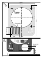
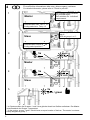
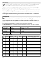
Abmessungen
Dimensions
Lieferumfang
Scope of delivery
Einbauanleitung
Installation instructions
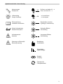
Warnung vor Elektrizität
Electricity warning
Drücken und halten für ...s
Press and hold für ...s
Dauerhaftes Leuchten
Lighting up Continuously
Schnelles Blinken
Fast blinking
Langsames Blinken
Slow blinking
Bestätigung
Confirmation
Signalstärke
Signal strength
Koppeln
Coupling
Filterwechsel
Filtereplacement
Weiter Informationen
Detailed description
...s
...x kurz drücken
...x short press
...x
Symbolverzeichnis / Icon directory
Aufmerksamkeit
Attention

4
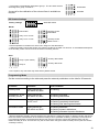
L
N
blau / blue
100-240 V AC
50/60 Hz
Gerät / Unit
rt / rd
sw / bla
gl / yl
rt / rd
bl / blu
li / pu
braun / brown
185 mm
231 mm
52 mm
65 mm 17 mm
135 mm
135 mm
4x Ø 6 mm
z.B. / e.g. NYM 3x1,5mm
100-240V 50/60Hz

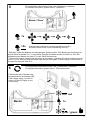
5
Offen
Open
Geschlossen
Closed
1
2
3
Externer Taster
External button
Sensor
Sensor
LED
LED
Interner Taster / Internal button
DIP-Schalter / DIP switch
Codierschalter / Coding switch
6-Pol Verbinder / 6-Pol connector
+
53 mm 70 mm

6
Master
Codierschalter nach Tab. S. 13
Coding switch acc. Tab p. 13
DIP-Schalter nach individuel-
len Anforderungen
DIP-switches acc. individuell
requirements
Slave
Codierschalter Position 0
Coding switch position 0
DIP2 Gruppe setzen 1
oder 2*
DIP2 set group 1 or 2*
Master
Slave
1
2
3
4
5 3x
grün / green
4 Für ausführliche Informationen bitte unter „Anlernvorgang“ nachlesen.
For detailed information, please refer to "Teach-in process".
* Im System sollten die Gruppen 1 und 2 eine gleiche Anzahl an Geräten aufweisen. Der Master
ist automatisch der Gruppe 1 zugeordnet.
* In the system, groups 1 and 2 should have an equal number of devices. The master is automa-
tically assigned to group 1.
rot / red
5s
5s
rot / red

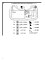
7
Master / Slave*
Filterwechsel alle 3 Monate oder
bei dauerhaft rot leuchtender LED
Filter change every 3 months or
when or if the LED lights up red
continuously
5
6 Für ausführliche Informationen bitte unter „Filterwechsel“ nachlesen.
For detailed information, please refer to "Filterreplacement".
Für ausführliche Informationen bitte unter „Bedienung“ nachlesen.
For detailed information, please refer to "Operation".
3x
grün / green
Master
rot / red
1x
1x
>5s Sommermodus aktivieren, endet automatisch nach 8 h
activate summer mode, ends automatically after 8 h
* Über den Taster des Masters wird das gesamte System bedient. Eine Bedienung des Slaves än-
dert die Stufe an diesem für 1 h, nach dieser Zeit gibt der Master wieder sie Stufe vor. Eine Stu-
fenänderung am Master wird nach 5-7s vom Slave übernommen.
* The entire system is operated via the button on the master. Operating the slave changes the level
on it for 1 hour, after this time the master specifies the level again. A level change on the master is
accepted by the slave after 5-7s.

8
Slave
3x > -50 dB
2x > -75 dB
1x > -90 dB
1x < -90 dB
grün / green
grün / green
grün / green
rot / red
7 Für ausführliche Informationen bitte unter „Signalstärke“ nachlesen.
For detailed information, please refer to "Signal strength".
1x
2x rot / red kein Master gekoppelt
no master coupled

9
Temperatureinsatzbereich: - 15°C bis + 40°C
Einsetzbar bei einer relativen Luftfeuchte bis 65% im Innenraumbereich (nicht kondensierend). Bei
Überschreitung der Einsatzgrenzen Gerät ausschalten und Innenblenden schließen. Frischluftzufuhr
durch Fensterlüftung sicherstellen.
Einsatzbereich
Positionieren Sie das Gerät nicht oberhalb von empfindlichen Möbeln, Oberflächen oder Bildern, die
Wand unter den Geräten soll „frei“ bleiben. Positionieren Sie das Gerät nicht oberhalb oder in der
Nähe von Raumthermostaten.
Einbauposition
Vorsicht! Jede Montagearbeit (Netzanschluss und Einstellung der Miniaturschalter) darf nur bei
abgetrennter Netzspannung erfolgen.
Machen Sie vor Anschluss des Lüftungsgerätes an die Netzspannung alle Anschlussleitungen
spannungsfrei.
(Abtrennung vom Netz mit mindestens 3 mm Kontaktöffnung, z.B. elektr. Sicherung).
Jeder zum Lüfter gehörende Stromkreis muss mit einem Fehlerstromschutz (z.B. Fl - Schalter)
ausgestattet sein.
Elektrischer Anschluss nur durch einen Fachmann.
Zusätzliche Installationen und elektrische Bauelemente im Lüftungsgerät sind unzulässig! Anschluss-
bilder für weitere Lüfterfunktionen auf Anfrage.
Elektrischer Anschluss
Technische Daten
Entsorgen Sie die Verpackung sortenrein. Wenn Sie sich vom Gerät trennen möchten, entsor-
gen Sie es zu den aktuellen Bestimmungen. Auskunft erteilt die kommunale Stelle.
Entsorgen
Inhalt DE
Eingangspannung: 100-240 V AC 50/60 Hz
Ausgangsspannung: 12 V DC SELV max. 24 W
Funkfrequenz: 868 MHz (bidirectional)
Allgemeine Informationen 9
Funksystem, Feuchteregelung 10
Anlernvorgang / Einrichtung des Systems 10
Bedienung / externe Steuermöglichkeiten 11
Filterwechsel 12
Signalstärke 12
Codierschaltereinstellungen 12
DIP-Schalter Einstellungen 13
Programmiermodus 13
Entkoppeln einer Komponente 14
Zurücksetzen auf Werkseinstellungen 14
Dieses Dokument richtet sich ausschließlich an Fachpersonal. Installationen oder Einstellungen dür-
fen nur von Fachpersonal durchgeführt werden.
Dieses Dokument soll von den Nutzern aufbewahrt und im Falle von Arbeiten am Gerät an das Fach-
personal übergeben werden.
Wartung, Filterwechsel und Reinigung darf nicht von Kindern und Personen durchgeführt werden, die
aufgrund ihrer physischen, sensorischen oder geistigen Fähigkeiten oder ihrer Unerfahrenheit oder
Unkenntnis nicht in der Lage sind, diese sicher durchzuführen.
Zu dieser Einbauanleitung

10
Funksystem
Feuchteregelung
Feuchteregelung Funkblende
Die Feuchteregelung Funkblende (FB) erfolgt durch Abgleich der absoluten Feuchtigkeit zwischen
Innen- und Außenklima. Bei Geräten, die paarweise im Reversierbetrieb lüften, kann der in der Blen-
de integrierte Feuchte-/Temperatursensor sowohl die Parameter der Abluft als auch die der Zuluft
erfassen. Der Lüftungsbetrieb wird entsprechend der vorliegenden Werte geregelt und vermieden,
dass durch einen erhöhten Luftaustausch die Luftfeuchtigkeit im inneren der Nutzungseinheit auf-
grund erhöhter Außenluftfeuchtigkeit ansteigt.
Klassische Feuchteregelung
Bei der klassischen Feuchteregelung wird anhand der gemessenen Werte von relativer Luftfeuchtig-
keit und Temperatur der Abluft auf die relative Luftfeuchtigkeit bei 22°C (Normbedingung) zurückge-
rechnet, praktisch eine Regelung nach absoluter Luftfeuchtigkeit. Der ermittelte Wert dient dann zur
Regelung des Volumenstroms zwischen 50% und 70% relativer Luftfeuchtigkeit bei 22°C. Praktisch
eine Regelung zwischen 9,7 g/m³ (untere Schaltschwelle) und 13,6 g/m³ (obere Schaltschwelle)
absoluter Feuchtigkeit. Die vorliegende Außenluftfeuchtigkeit wird dabei nicht berücksichtigt.
Das Funksystem besteht immer aus einem Master und max. 10 Slave Geräten bzw. Steuerungen.
Der Master kann dabei eine Funkblende mit angeschlossenem Lüftungsgerät oder auch eine Steue-
rung (5/UNI-RF oder 5/SC-RF) sein.
Der Master gibt im System den Betriebsmodus und die Stufe in Abhängigkeit von Steuerbefehlen
oder Sensorwerten vor und kommuniziert dies in Richtung der Slave Komponenten. Von den Slave
Geräten werden regelmäßig Betriebsparameter abgefragt, um die Stabilität des Systems und der
Funkverbindung dauerhaft gewährleisten zu können. Während der Kommunikation überprüfen die
Teilnehmer stets Sende– und Empfangsstärke und passen die Sendeleistung entsprechend der An-
forderungen an.
Bei der Kommunikation handelt es sich um eine verschlüsselte bidirektionale Kommunikation. Es ist
sichergestellt, dass nur die aneinander angelernten Geräte miteinander kommunizieren. Zur Auf-
rechterhaltung der Stabilität und Synchronität des Systems, werden empfangene Daten und Befehle
stets vom Empfänger in Richtung des Senders bestätigt.
4 Anlernvorgang / Einrichtung des Systems
Jede mit einem Funkmodul versehene Komponente im System (Steuerung 5/SC-RF oder 5/UNI-RF
oder Funkinnenblende 9/IBF-RF) kann als Master konfiguriert werden. Es wird empfohlen eine zent-
ral platzierte Komponente mit guter Lage zur Messung von Temperatur– und Feuchtigkeitswerten als
Systemmaster zu wählen. Der Master sollte nicht in einem Nebenraum, wie z.B. einem Hauswirt-
schaftsraum mit unter Umständen temporär stark schwankenden Feuchtigkeitswerten, platziert sein.
Bevor der Anlernvorgang gestartet werden kann, muss der Master konfiguriert werden. Dazu den
Codierschalter entsprechend nachfolgender Tabelle auf den angeschlossenen Lüftertyp einstellen.
DIP-Schalter (Intervallbetrieb, Nachlaufzeit und Feuchteregelung) nach individuellen Bedürfnissen
konfigurieren.
An der Slave Komponente wird der Codierschalter während des Anlernvorgangs auf Position 0 be-
lassen. Sollte ein Mischsystem vorliegen, d.h. eine vom Master abweichende Lüftungskomponente
verbaut sein, kann der Codierschalter nach erfolgreichem Anlernvorgang entsprechend der nachfol-
genden Tabelle verstellt werden. Ist die Komponente identisch zum Master, kann die Position 0 be-
lassen werden.
Über den DIP-Schalter 2 wird die Slave Komponente einer Lüftungsgruppe (Gruppe 1 oder 2) zuge-
ordnet. Über diese Zuordnung wird konfiguriert welche Komponenten gemeinsam im Zuluftbetrieb
und welche im Abluftbetrieb arbeiten. Der Master ist automatisch der Gruppe 1 zugeordnet. Nach
erfolgter Einrichtung und Anlernvorgang aller Komponenten sollten beiden Gruppen eine identisch
Anzahl an Lüftern zugeordnet sein.
Nach erfolgter Installation / elektrischem Anschluss müssen die einzelnen Systemkompo-
nenten jeweils mit dem Systemmaster gekoppelt werden.

11
Ist die Einrichtung aller Lüftungskomponenten abgeschlossen, kann der eigentliche Anlernvorgang
gestartet werden (siehe auch Abb. 4).
1. Internen Taster auf der Steuerung des Masters für 5 Sekunden betätigen und dann loslas-
sen. LED blinkt weiterhin rot im Sekundentakt, Anlernmodus aktiviert.
2. Internen Taster des Slave ebenfalls für 5 Sekunden betätigen und dann loslassen. LED
blinkt weiterhin rot im Sekundentakt
3. Bei erfolgreichem Anlernvorgang erlischt die rote LED bei den beteiligten Komponenten. Die
grüne LED leuchtet 3x zur Bestätigung des erfolgreichen Anlernvorgang auf.
Dieser Vorgang muss für jeden Slave im System wiederholt werden. Wird vom Master oder Slave
keine passende Komponente zum Anlernen gefunden, wird der Anlernmodus automatisch nach 120
Sekunden beendet.
5 Bedienung / externe Steuermöglichkeiten
Die Bedienung der Volumenstromstufen erfolgt rollend. Pro Tastendruck wird dabei der Volumen-
strom um eine Stufe verringert. Ist der niedrigste Volumenstrom oder AUS (je nach gewähltem Pro-
gramm) erreicht, wird mit dem nächsten Tastendruck auf die höchste Stufe geschaltet.
Ein langer Tastendruck führt bei Reversiergeräten mit Wärmerückgewinnung zur Deaktivierung der
Wärmerückgewinnung, den so genannten Sommermodus. Die Reversierzeit beträgt dann 1 h.
Eine Bedienung des Slave Gerätes führt zu einer temporären Änderung des Volumenstroms an dem
jeweiligen Gerät. Nach einer Stunde bekommt der Slave die Stufenvorgabe wieder vom Master.
Smart Comfort 5/SC-RF als Master
Einen deutlich komfortablere Bedienung kann mittels Smart Comfort Steuerung 5/SC-RF realisiert
werden. Dazu wird diese, wie in der entsprechenden Einbauanleitung beschrieben, als Master im
System angelernt bzw. konfiguriert. Folglich werden die zu bedienenden Funkinnenblenden bzw. die
an diese angeschlossenen Geräte als Slave an die Steuerung angelernt.
Die Verstellung der Volumenstromstufe, die Aktivierung und Deaktivierung des feuchtegeführten
Betriebes oder die schnelle Benutzung der Komfortfunktionen wie die Nachtabsenkung, Intensivlüf-
tung, Party– und Sommermodus können schnell per Tastendruck ausgeführt werden.
Des Weiteren hält die Smart Comfort Steuerung einen 0-10 V Steuereingang zur Steuerung des
Systems durch eine übergeordnete Haus Automatisierung bereit.
Die temporäre und lokale Bedienung einer einzelnen Funkinnenblenden ist, wie bereits beschrieben,
nach wie vor möglich. Die Gültigkeit der Änderung beträgt weiterhin 1 Stunde.
Universalsteuerung 5/UNI-RF als Master und Funkbrücke
Soll das Funksystem mit einem einfachen Serienschalter oder mittels übergeordneter Hausautomati-
sierung betrieben werden, kann eine Universalsteuerung vom Typ 5/UNI-RF als Master im System
konfiguriert werden.
Die Steuerung kann direkt hinter einem Serienschalter verbaut werden und hält einen 0-10V Nieder-
spannungseingang zur Steuerung des Systems durch eine übergeordnete Steuerung bereit. Die
entsprechenden Spannungen können der Einbauanleitung der Universalsteuerung entnommen wer-
den.
Die Funkblenden im System sind in diesem Fall wieder als Slave zu konfigurieren und können wei-
terhin lokal für eine begrenzte Zeit verstellt werden.
Steuerung per Fernbedienung RC-EO oder Homee App
Durch das optional erhältliche Funkmodul UNI-EO kann der Funkmaster im System ertüchtigt wer-
den mittels der EnOcean Funkfernbedienung RC-EO oder Homee App gesteuert zu werden. Das
Modul wird auf den 6-poligen Steckverbinder der Steuerung des Master aufgesteckt. Die Verbindung
vom Funkmodul UNI-EO mit der Fernbedienung RC-EO oder des Homee SmartHome Systems sind
in den entsprechenden Anleitung aufgeführt und in der Homee App beschrieben.
4 Anlernvorgang / Einrichtung des Systems
Die Bedienung der Funkblende bzw. des Funksystems erfolgt im einfachsten Fall über
den externen Taster (siehe Abb. 3) des Masters. Der Taster befindet sich an der rechten
Seite der entsprechenden Blende.

12
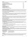
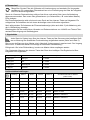
Lüftertyp Stufe 0
Stufe I
Stufe II
Stufe III
Sonderfunktion DIP 4 aktiviert
(siehe unten)
0 Slave - - - -
1 RA 15-60 AUS / OFF 15 m³/h 30 m³/h 60 m³/h
2 RA 15-60 15 m³/h 30 m³/h 45 m³/h 60 m³/h
3 e² AUS / OFF 15 m³/h 30 m³/h 38 m³/h e²kurz / e²short
4 e² 15 m³/h 20 m³/h 30 m³/h 38 m³/h e²kurz / e²short
5 e²60 AUS / OFF 15 m³/h 30 m³/h 40 m³/h e²60kurz / e²60short
6 e²60 5 m³/h 15 m³/h 30 m³/h 40 m³/h e²60kurz / e²60short
7 e²60 AUS / OFF 15 m³/h 30 m³/h 60 m³/h e²60kurz / e²60short
8 e²60 15 m³/h 30 m³/h 45 m³/h 60 m³/h e²60kurz / e²60short
C e²60** AUS / OFF 15 m³/h 30 m³/h 60 m³/h e²60kurz / e²60short
D e²60** 15 m³/h 30 m³/h 45 m³/h 60 m³/h e²60kurz / e²60short
E 0-10 V
Codierschaltereinstellungen
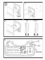
Durch ein Lösen der Rastverbindung mittig auf der linken und rechte Seite, kann die Abdeckung
abgenommen werden. Den neuen oder gewaschenen (nur Schaumfilter, z.B. unter kalten Wasser)
Filter einlegen.
Die Filterwechselanzeige wird mit einem kurzen Druck auf den internen Taster zurückgesetzt. Ein
erfolgreiches Zurücksetzen wird mit einem dreimaligen roten Aufleuchten signalisiert.
Nach erfolgreichem Zurücksetzen der Filterwechselanzeige (siehe auch Abb. 5) die Abdeckung wie-
der in Offenstellung einrasten.
Bitte beachten Sie die ausführlichen Hinweise und Dokumentationen von LUNOS zum Thema Filter-
wechsel/Filterreinigung und Gerätehygiene.
6 Filterwechsel
7 Signalstärke
Dazu muss der Slave an einen Master, wie in Abschnitt „Anlernvorgang“ angelernt sein. Der Vorgang
kann bis zu 10 Sekunden dauern und erfolgt mit maximaler Sendeleistung.
Erfolgt nach 10 s keine Rückmeldung, konnte vom Master nichts empfangen werden.
Zum Starten der Messung den internen Taster des Slave kurz betätigen. Das Ergebnis wird über
integrierte LEDs signalisiert.
Rückmeldung LED Qualität Gemessener Wert (RSSI)
3x lang grün Sehr gut > -50 dB
2x lang grün Gut > -75 dB
1x lang grün Befriedigend > -90 dB
1x lang rot Schlecht < -90 dB
Überprüfen Sie den Filter alle 3 Monate auf Verschmutzung und wechseln Sie ihn gegebe-
nenfalls aus. Ein notwendiger Filterwechsel bzw. eine Filterreinigung wird über die integrierte
rote LED dauerhaft signalisiert.
Jeder Slave im System kann über den internen Taster auf der Steuerung des jeweiligen Gerä-
tes zur Messung der Qualität der Funkverbindung aufgefordert werden (siehe auch Abb. 5).

13
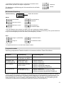
Intervall AUS
alle 4 Std. 30 min *
alle 2 Std. 15 min *
Weißer DIP-Schalter Werkseinstellung
Feuchteregelung
deaktiviert
-
Feuchteregung
Funkblende (FB)**
* Der Intervallbetrieb wird je Gerät in der Stufe II der oben aufgeführten Tabelle ausgeführt.
** Bei der Feuchteregelung Funkblende (FB) werden die Außenkonditionen berücksichtigt. Eine genauere Beschrei-
bung der Feuchteregelung ist unter dem Punkt „Feuchteregelung“ zu finden.
1 2 3 4
1 2 3 4
Sensordaten Master
Sensordaten senden *
1 2 3 4
Gruppe 1 (wie Master)
Gruppe 2
1 2 3 4
DIP-Schalter Einstellung
Master
Slave
* Im System darf immer nur ein Slave Sensordaten senden.
Funktion Voraussetzung Rückmeldung LED
Werksreset Codierschalter auf F
DIP-Schalter auf „0000“ 5x Blinken
Intelligenz* der
Feuchteregelung Codierschalter auf F
DIP-Schalter „000+“ 1x Blinken aktiviert
2x Blinken deaktiviert
LED Funktion Codierschalter beliebig
auf 0-E, nicht F
1x Blinken Vollfunktion
2x Blinken vollständig deaktiviert
3x Blinken Filterwarnung deaktiviert
Lüftungsbetrieb Codierschalter auf F
DIP-Schalter auf „00+0“ 1x Blinken Balanciert
2x Blinken dynamische Disbalance (DIBt)
3x Blinken erweiterte dynamische Disbalance
Steuerung entsprechend Tabelle einstellen und externen seitlichen Taster 30s drücken.
Programmiermodus
* Bei der im Standard aktivierten intelligenten Feuchteregelung wird anhand der gemessenen Werte von relativer
Luftfeuchtigkeit und Temperatur auf die relative Luftfeuchtigkeit bei 22°C (Normbedingung) zurückgerechnet, prak-
tisch eine Regelung nach absoluter Luftfeuchtigkeit. Der ermittelte Wert dient dann zur Regelung des Volumen-
stroms zwischen 50 % und 70 % relativer Luftfeuchtigkeit bei 22°C. Diese Funktion hat nur Auswirkung bei der
Verwendung der klassischen Feuchteregelung (siehe auch Abschnitt „Feuchteregelung“).
deaktiviert
aktiviert
1 2 3 4
** Der Master ist automatisch Gruppe 1 zugeordnet. Die beiden Slave
Geräte werden per DIP 2 der Gruppe 2 zugeordnet.
Ein Anleitung zur Kalibrierung der Volumenströme ist auf Anfra-
ge erhältlich.

14
Entkoppeln einer Komponente (Slave)
Zum Entkoppeln eines Gerätes muss der Master noch in Betrieb sein. Bei dem Gerät, dass entkop-
pelt werden soll (kein Master), muss der interne Taster auf der Steuerung für 15 Sekunden gedrückt
gehalten werden.
Die grüne LED fängt an dauerhaft im Sekundentakt zu blinken. Die erfolgreiche Entkopplung des
Gerätes aus dem System bzw. vom Master wird durch dreimaliges Aufleuchten der roten LED bestä-
tigt.
Ist der Master nicht mehr in Betrieb oder soll der Master entkoppelt werden, muss die Komponente
auf Werkseinstellungen zurückgesetzt werden. Das Vorgehen hierzu ist im nächsten Abschnitt be-
schrieben.
Zurücksetzen auf Werkseinstellungen
Zur Wiederherstellung der Werkseinstellungen (abgesehen von den mechanischen Bauteilen wie
Codierschalter und DIP– Schalter) muss der interne Taster auf der Steuerung für 30 Sekunden ge-
drückt und gehalten werden.
Weißer DIP-Schalter
Werkseinstellung Position 3

15
Temperature application range: - 15°C to + 40°C.
Can be used at a relative humidity of up to 65% indoors (non-condensing). If the operating limits are
exceeded, switch off the device and close the inner screens. Provide fresh air supply by means of
window ventilation.
Range of Application
Do not position the device above sensitive furniture, surfaces or pictures, the wall below the devices
should remain "free". Do not position the device above or near room thermostats.
Installation Position
Caution! Any installation work (mains connection and setting of the miniature switches) may only
be carried out with the mains voltage disconnected.
Before connecting the ventilation unit to the mains voltage, de-energise all connection lines.
(Disconnection from the mains with at least 3 mm contact opening, e.g. electrical fuse).
Each circuit belonging to the fan must be equipped with a residual current protection (e.g. Fl -
switch).
Electrical connection only by a specialist.
Additional installations and electrical components in the ventilation unit are not permitted! Connection
diagrams for further fan functions available on request.
Electrical Connection
Technical Data
This document is intended for technical personnel only. Installations or settings may only be carried
out by qualified personnel.
This document should be kept by the users and handed over to the qualified personnel in the event
of work on the device.
Cleaning must not be carried out by children and persons who are unable to do so safely due to their
physical, sensory or mental abilities or their inexperience or lack of knowledge.
About this installation instructions
Dispose of the packaging sorted by materials. If you wish to discard the device, dispose of it in
accordance with the current regulations. Information can be obtained from the municipal autho-
rity in charge.
Disposal
Contents EN
Input voltage: 100-240 V AC 50/60 Hz
Output voltage: 12 V DC SELV max. 24 W
Radio frequency: 868 MHz (bidirectional)
General Information 15
Radio System, Humidity Control 16
Teach-in Procedure / System Setup 16
Operation / External Control Options 16
Filter Change 17
Signal Strength 17
Coding Switch Settings 17
DIP Switch Settings 18
Programming Mode 18
Decoupling of a Component 19
Reset to Factory Settings 19

16
Radio System
Humidity Control
Humidity control radio screen
The humidity control radio screen is performed by balancing the absolute humidity between indoor
and outdoor climate. In the case of units that ventilate in pairs in reversing mode, the humidity/
temperature sensor integrated in the screen can record both the parameters of the exhaust air and
those of the supply air. The ventilation mode is controlled according to the existing values and it is
prevented that the humidity inside the utilisation unit rises due to increased outside air humidity as a
result of an increased air exchange.
Classic humidity control
In classic humidity control, the measured values of relative humidity and temperature of the exhaust
air are used to calculate back to the relative humidity at 22°C (standard condition), practically a con-
trol according to absolute humidity. The determined value is then used to control the volume flow
between 50% and 70% relative humidity at 22°C. Practically a control between 9.7 g/m³ (lower swit-
ching threshold) and 13.6 g/m³ (upper switching threshold) of absolute humidity. The existing outside
air humidity is not taken into account.
The radio system always consists of a master and max. 10 slave devices or controls. The master can
be a radio screen with a connected ventilation unit or a control unit (5/UNI-RF or 5/SC-RF).
The master specifies the operating mode and the stage in the system depending on control com-
mands or sensor values and communicates this to the slave components. Operating parameters are
regularly queried from the slave devices in order to be able to permanently guarantee the stability of
the system and the radio connection. During communication, the participants always check the trans-
mission and reception strength and adjust the transmission power according to the requirements.
The communication is an encrypted bidirectional communication. It is ensured that only the devices
that have been connected to each other communicate with each other. To maintain the stability and
synchronicity of the system, data and commands received are always confirmed by the receiver in
the direction of the sender.
Teach-in Procedure / System Setup
Any component in the system equipped with a radio module (control 5/SC-RF or 5/UNI-RF or radio
inner screen 9/IBF-RF) can be configured as a master. It is recommended to choose a centrally
placed component with a good location for measuring temperature and humidity values as the sys-
tem master. The master should not be placed in an adjoining room, such as a utility room, where
humidity values may be temporarily subject to large fluctuations.
Before the teach-in process can be started, the master must be configured. To do this, set the coding
switch to the connected fan type according to the following table. Configure the DIP switches (interval
operation, run-on time and humidity control) according to individual requirements.
At the slave component, the coding switch is left in position 0 during the teach-in process. If a mixed
system is used, i.e. if a ventilation component is installed that differs from the master, the coding
switch can be set according to the following table after the teach-in process has been successfully
completed. If the component is identical to the master, position 0 can remain unchanged.
The slave component is assigned to a ventilation group (group 1 or 2) via DIP switch 2. This assign-
ment is used to configure which components work together in supply air mode and which work in
exhaust air mode. The master is automatically assigned to group 1. After all components have been
set up and the teach-in process has been completed, an identical number of fans should be assigned
to both groups.
After being installed and electrically connected, the individual system components must
each be coupled with the system master.

17
Once the setup of all ventilation components is complete, the actual teach-in process can be started
(see also Fig. 4).
1 Press the internal pushbutton on the master control for 5 seconds and then release it. LED
continues to flash red at one-second intervals - the teach-in mode activated.
2 Press the internal pushbutton of the slave also for 5 seconds and then release it. LED conti-
nues to flash red at one-second intervals.
3 If the teach-in process is successful, the red LED of the components involved will go out. The
green LED lights up 3 times to confirm the successful teach-in process.
This procedure must be repeated for each slave in the system. If no component suitable for teach-in
is found by the master or slave, the teach-in mode will automatically be terminated after 120 seconds.
Operation / External Control Options
In the most basic case, the radio screen or radio system is operated via the external pushbutton (see
Fig. 3) of the master. The button is located on the right side of the corresponding screen.
The operation of the volume flow stages is carried out in a rolling mode. Each time the button is pres-
sed, the volume flow is decreased by one stage. When the lowest volume flow or OFF (depending on
the selected program) is reached, the next push of the button switches to the highest level.
In reversing units with heat recovery, a long press on the button leads to deactivation of the heat
recovery, the so-called summer mode. The reversing time is then 1 h.
An operation of the slave unit leads to a temporary change of the volume flow at the respective unit.
After one hour, the slave will receive the stage specification from the master again.
Smart Comfort 5/SC-RF as Master
A much more convenient operation can be achieved using the Smart Comfort control 5/SC-RF which
can be taught in or configured as a master in the system, as described in the corresponding installati-
on instructions. Consequently, the radio-controlled inner screens to be operated or the devices
connected to them are taught in to the control unit as slaves.
The adjustment of the volume flow rate level, the activation and deactivation of the humidity-
controlled operation or the quick use of the comfort functions such as night setback, intensive ventila-
tion, party and summer mode can be carried out quickly by pressing a button.
Furthermore, the Smart Comfort control provides a 0-10 V control input for control of the system by a
higher-level home automation system.
The temporary and local operation of a single radio inner screen is still possible, as already descri-
bed. The validity of the change is still 1 hour.
Universal Control 5/UNI-RF as Master and Wireless Bridge
If the radio system is to be operated with a simple series switch or by means of higher-level home
automation, a universal control type 5/UNI-RF can be configured as the master in the system.
The control can be installed directly behind a series switch and has a 0-10V low-voltage input for
controlling the system by a higher-level control. The corresponding voltages can be found in the
installation instructions for the universal control.
In this case, the radio screens in the system must again be configured as slaves and can still be
adjusted locally for a limited time.
Control via remote control RC-EO or Homee App
By means of the optionally available radio module UNI-EO the radio master in the system can be
enabled to be controlled via the EnOcean radio remote control RC-EO or Homee App. The module is
plugged onto the 6-pin connector of the master control. The connection of the UNI-EO radio module
with the RC-EO remote control or the Homee SmartHome system is described in the corresponding
instructions and in the Homee App.
Teach-in Procedure / System Setup
In the most basic case, the radio screen or radio system is operated via the external push-
button (see Fig. 3) of the master. The button is located on the right side of the correspon-
ding screen.

18
Fan type Stage 0
Stage I
Stage II
Stage III
Special Function DIP 4 activated
(see below)
0 Slave - - - -
1 RA 15-60 AUS / OFF 15 m³/h 30 m³/h 60 m³/h
2 RA 15-60 15 m³/h 30 m³/h 45 m³/h 60 m³/h
3 e² AUS / OFF 15 m³/h 30 m³/h 38 m³/h e²kurz / e²short
4 e² 15 m³/h 20 m³/h 30 m³/h 38 m³/h e²kurz / e²short
5 e²60 AUS / OFF 15 m³/h 30 m³/h 40 m³/h e²60kurz / e²60short
6 e²60 5 m³/h 15 m³/h 30 m³/h 40 m³/h e²60kurz / e²60short
7 e²60 AUS / OFF 15 m³/h 30 m³/h 60 m³/h e²60kurz / e²60short
8 e²60 15 m³/h 30 m³/h 45 m³/h 60 m³/h e²60kurz / e²60short
C e²60** AUS / OFF 15 m³/h 30 m³/h 60 m³/h e²60kurz / e²60short
D e²60** 15 m³/h 30 m³/h 45 m³/h 60 m³/h e²60kurz / e²60short
E 0-10 V
Coding Switch Settings
The cover can be removed by loosening the snap-in connection in the middle on the left and right
side. Insert the new or washed (foam filter only, e.g. under cold water) filter.
The filter change indicator can be reset by briefly pressing the internal pushbutton. A successful reset
is indicated by three red flashes.
After successfully resetting the filter change indicator (see also Fig. 5), snap the cover back into the
open position.
Please observe the detailed instructions and documentation provided by LUNOS on the subject of
filter change/filter cleaning and device hygiene.
Filter Change
Signal Strength
For this purpose, the slave must be taught in to a master as described in the section "Teach-in Pro-
cedure". The procedure can take up to 10 seconds and is performed with maximum transmitting
power.
If no response is received after 10 s, nothing could be received from the master.
To start the measurement, briefly press the internal pushbutton of the slave. The result is indicated
by integrated LEDs.
LED Feedback Quality Measured Value (RSSI)
3x long green Very good > -50 dB
2x long green Good > -75 dB
1x long green Satisfactory > -90 dB
1x long red Bad < -90 dB
Check the filter for contamination every 3 months and replace it if necessary. A necessary
filter change or filter cleaning is permanently indicated by the integrated red LED.
Each slave in the system can be requested to measure the quality of the radio connection via
the internal button on the control of the respective device (see also Fig. 5).

19
Interval OFF
every 4 hrs. 30 min *
every 2 hrs. 15 min *
White DIP-switch Factory settings
Humidity control
deactivated
-
Humidity control
Radio screen **
* Interval operation is carried out for each unit in stage II of the table above.
** With the humidity control radio screen, the outdoor conditions are taken into account. A more detailed description
of the humidity control can be found in the section "Humidity Control".
1 2 3 4
1 2 3 4
Sensory data master
Sensory data send *
1 2 3 4
Group 1 (like master)
Group 2
1 2 3 4
DIP-Switch Settings
Master
Slave
* In the system, only one slave may send sensory data at a time.
Function Condition LED Feedback
Factory reset Coding switch at F
DIP-switch at „0000“ 5x flashing
Intelligence* of the
humidity control Coding switch at F
DIP-switch at „000+“ 1x flashing activated
2x flashing deactivated
LED function Coding switch anywhere
on 0-E, not F
1x flashing full function
2x flashing completely deactivated
3x flashing filter warning deactivated
Ventilation mode Coding switch at F
DIP-switch at „00+0“ 1x flashing balanced
2x flashing dynamic disbalance
3x flashing extended dynamic disbalance
Set the control according to the table and press the external pushbutton on the side for 30 seconds.
Programming Mode
* With the intelligent humidity control activated in the standard, the measured values of relative humidity and tempe-
rature are used to calculate back to the relative humidity at 22°C (standard condition), practically a control accord-
ing to absolute humidity. The determined value is then used to control the volume flow between 50% and 70%
relative humidity at 22°C. This function only has an effect when using the classic humidity control (see also section
"Humidity Control").
** The master is automatically assigned to group 1. The two slave devices
are assigned to group 2 via DIP 2.
A manual for the calibration of the volume flows is available on
request.
deactivated
activated
1 2 3 4

20
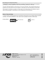
LUNOS Germany
LUNOS Lüftungstechnik GmbH & Co. KG Phone +49 30 362 001-0
für Raumluftsysteme Fax +49 30 362 001-89
Wilhelmstr. 31 info@lunos.de
13593 Berlin ∙ Germany www.lunos.de
E426 09.22
Decoupling of a Component (Slave)
To decouple a device, the master must still be in operation. For the device that is to be decoupled
(no master), the internal pushbutton on the control must be pressed for 15 seconds.
The green LED starts flashing continuously at one-second intervals. The successful decoupling of
the device from the system or from the master is confirmed by the red LED lighting up three times.
If the master is no longer in operation or if the master is to be decoupled, the component must be
reset to factory settings. The procedure for this is described in the next section.
Reset to Factory Settings
To reset to factory settings (apart from the mechanical components such as coding switches and DIP
switches), the internal pushbutton on the control must be pressed and held for 30 seconds.
White DIP-switch
Factory settings Position 3
-
 1
1
-
 2
2
-
 3
3
-
 4
4
-
 5
5
-
 6
6
-
 7
7
-
 8
8
-
 9
9
-
 10
10
-
 11
11
-
 12
12
-
 13
13
-
 14
14
-
 15
15
-
 16
16
-
 17
17
-
 18
18
-
 19
19
-
 20
20


Lunos 9/IBF-RF Inner radio cover incl. control Installationsanleitung
- Typ
- Installationsanleitung
in anderen Sprachen
Verwandte Artikel
-
Lunos 5/SC-RF + 5/UNI-RF wireless connection Installationsanleitung
-
-
Lunos 5/UNI-FT Installationsanleitung
-
-
-
-
-
-
-