POLYTRON TSM 1000 HD PolySelect SAT IF channel converter compact HD Bedienungsanleitung
- Kategorie
- Ladegeräte
- Typ
- Bedienungsanleitung

SAT-ZF Kanalaufbereitung
SAT-IF Channel processing unit
PolySelect TSM 1000 HD
Bedienungsanleitung/
User manual
0901467 V2

2
Sicherheitsvorkehrungen
Vor dem Arbeiten am Grundgerät TSM 1000 bitte
unbedingt folgende Sicherheitsbestimmungen sorg-
fältig lesen!
ACHTUNG Das Öffnen des Gerätes sollte nur von au-
torisiertem Fachpersonal durchgeführt werden.
Zum Aus- und/oder Einbau eines Moduls muss das
Grundgerät immer stromlos sein!
Netzanschluss und Netzkabel
Das Gerät darf nur an einem Stromnetz mit einer Span-
nung von 230 V~ / 50 Hz betrieben werden.
Anschlusskabel
Anschlusskabel immer stolperfrei verlegen!
Erdung der Anlage
Nach den EN 50 083 / VDE 0855 Bestimmungen muss
die Anlage den Sicherheitsbestimmungen wie z.B. Er-
dung, Potenzialausgleich, etc. entsprechen.
Feuchtigkeit und Aufstellungsort
Das Gerät darf nicht Tropf- oder Spritzwasser ausge-
setzt werden. Bei Kondenswasserbildung unbedingt
warten, bis das Gerät wieder trocken ist.
Umgebungstemperatur und Hitzeeinwirkung
Die Umgebungstemperatur darf +50 °C nicht überschrei-
ten. Die Lüftungsschlitze des Gerätes dürfen auf keinen
Fall abgedeckt werden. Zu starke Hitzeeinwirkung oder
Wärmestau beeinträchtigen die Lebensdauer des Gerä-
tes und können eine Gefahrenquelle sein. Um einen
Wärmestau zu verhindern und eine gute Durchlüftung zu
garantieren, sollte das Gerät nur senkrecht montiert
werden (z.B. an einer Wand).
Das Gerät darf nicht direkt über oder in der Nähe von
Wärmequellen (z.B. Heizkörpern, Heizungsanlagen o.ä.)
montiert werden, wo das Gerät Hitzestrahlung oder
Öldämpfen ausgesetzt ist.
Wegen der Brandgefahr durch Überhitzung oder Blitz-
einschlag ist es empfehlenswert, das Gerät auf einer
feuerfesten Unterlage zu montieren.
Sicherungen
Sicherungen sollten nur von autorisiertem Fachpersonal
gewechselt werden. Es dürfen nur Sicherungen des
gleichen Typs eingesetzt werden.
Bedingungen zur Sicherstellung der elektromagneti-
schen Verträglichkeit (EMV)
Alle Abdeckungen und Schrauben müssen fest montiert
und angezogen sein, Kontaktfedern dürfen nicht oxidiert
oder verbogen sein.
Safety precautions
Before working on the base unit TSM 1000 please
read the following safety precautions carefully!
ATTENTION The unit should only be opened by
qualified persons.
For removement and/or installation of a module the
base unit must always be currentless!
Mains connection and mains cable
The unit may be only operated with a mains voltage of
230 V~ / 50 Hz.
Connection cable
Lay cables that they cannot be tripped over!
Grounding of the system
According to the regulations EN 50 083 / VDE 0855 the
plant must correspond to the safety regulations e.g.
grounding, potential equalization, etc.
Humidity and place of assembly
The equipment may not be exposed dripping or splash-
water. In case of condensed water formation wait until
the device is dry again.
Ambient temperature and influence of heat
The ambient temperature must not exceed +50 °C. Don’t
cover the louvers of the device.
To strong heat effect or accumulation of heat impairs the
life span of the equipment and can be a source of dan-
ger.
In order to prevent an accumulation of heat and to guar-
antee a good aeration, the equipment should be only
perpendicularly installed (e.g. at a wall).
The unit must not be installed directly above or in the
immediate vicinity of heat sources (e.g. heating ele-
ments, heating systems or similarly.), where the equip-
ment is exposed to heat radiation or oil vapour.
Due to the risk of fire by overheating or lightning strike it
is recommendable to install the equipment on a non-
combustible base.
Fuses
Fuses should be changed only from authorized technical
personnel. Only fuses of the same type may be used
Precautions to ensure the electro magnetic compat-
ibility (EMV)
All covers and screws must tightly be fitted and should
be tightly fastened. Contact feathers should not be
oxidized or deformed.

3
Inhaltsverzeichnis
1 Beschreibung/ Description ......................................................................................... 4
2 Vorbereitungen/ Preparations .................................................................................... 5
3 Bedienung/ Operation ................................................................................................ 6
3.1 Programmierung/ Programming ......................................................................... 6
3.2 Programmierablauf / Programming procedure ................................................... 7
3.3 Einpegelung/ Level adjustment........................................................................... 8
3.4 Funktionen im Programmmenü/ Functions of programming menueFehler! Textmarke nicht
definiert.
3.4.1 Offset Einstellung/ Offset settings
............................... Fehler! Textmarke nicht definiert.
3.4.2
Funktion "parken"/ Function „parc“
.............................. Fehler! Textmarke nicht definiert.
3.5 Funktionen im Service-Menü/ Functions of service menue ................................ 9
3.5.1
Wiederherstellung der Grundeinstellung/ Restoration of basic settings
................. 9
4 Bauteile des TSM 1000 HD / Components of the TSM 1000 HD ...................... 10
5 Technische Daten/ Technical Data ................................................................... 11
5.1 Eingangsbereich / Input .................................................................................... 11
5.2 Ausgangsbereich/ Output ................................................................................. 11
5.3 Allgemeine Daten/ General data ....................................................................... 11
HINWEIS
Der Inhalt dieses Firmenhandbuches ist urheberrechtlich
geschützt und darf ohne Genehmigung des Verfassers
weder ganz noch teilweise in irgendeiner Form verviel-
fältigt oder kopiert werden. Änderungen in diesem Fir-
menhandbuch, die ohne Zustimmung des Verfassers
erfolgen, können zum Verlust der Gewährleistung bzw.
zur Ablehnung der Produkthaftung seitens des Herstel-
lers führen. Für Verbesserungsvorschläge ist der Ver-
fasser dankbar.
Verfasser:
Polytron-Vertrieb GmbH
Postfach 10 02 33
75313 Bad Wildbad
Germany
Unten stehende Hervorhebungen werden in diesem
Handbuch mit folgenden Bedeutungen verwendet:
HINWEIS gilt für technische Erfordernisse, die der
Benutzer der Geräte besonders beachten
muss, um eine einwandfreie Funktion der
Geräte/Anlage zu gewährleisten.
ACHTUNG bezieht sich auf Anweisungen, die genau
einzuhalten sind, um eine Beschädigung
oder Zerstörung des Gerätes zu vermeiden.
VORSICHT steht für Anweisungen, deren Nichtbeach-
tung eine Gefährdung von Personen nicht
ausschließt.
Bei Hinweisen auf ein durch eine Ortszahl versehenes
Bauteil z.B. (Bild 1/3) bezieht sich in diesem Beispiel der
Hinweis auf Bild 1 Ortszahl 3.
NOTE
The contents of this company manual are copyrighted
and must not be duplicated or copied in any form, either
partially or in full, without the prior consent of the editor.
Changes in this company manual which are carried out
without consent of the creator can lead to the loss of the
guarantee or to the rejection of the product liability on
the part of the manufacturer. The editor is grateful for
suggestions.
Editor:
Polytron-Vertrieb GmbH
Postfach 10 02 33
75313 Bad Wildbad
Germany
The following emphases are used in this manual with the
following meanings:
NOTE applies to technical requirements which
must be taken into account to ensure a
faultless function of the device/plant.
ATTENTION refers to instructions which have to be
adhered exactly to avoid damage or de-
struction of the device.
CAUTION applies to instructions whose nonob-
servance doesn't exclude the endanger-
ing of persons.
At references to a component provided by a place num-
ber (e.g. figure 1/3) the reference corresponds to picture
1 place number 3.

4
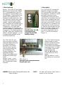
1 Beschreibung
Bei der TSM 1000 HD wird jeder
gewünschte analoge oder digitale
SAT-Transponder aus seiner ur-
sprünglichen Frequenzlage in ein
frei wählbares Frequenzraster um-
gesetzt. Nicht gewünschte Pro-
gramme scheiden dabei aus. Meh-
rere Einheiten können über einen
Verteiler zusammengeschaltet
werden. Jeder Kanalzug besitzt
eine automatische Verstärkungsre-
gelung (AGC), damit stehen alle
Transponder, auch bei Pegel-
schwankungen am Eingang, mit
dem eingestellten Systempegel am
Ausgang an. Die Speisespannung
für LNB’s kann über Steckbrücken
(Bild 1) auf die Eingänge 1, 4, und
8 aufgeschaltet werden und ist
kurzschlussgesichert.
Die TSM 1000 HD wird
durch eine leicht zu hand-
habende Bedienerführung
im Display-Dialog pro-
grammiert. Drei Tasten
sind für diese Program-
mierung vorhanden und
ein vierstelliges LED-
Display zeigt jeden Pro-
grammierschritt an.
Mit der Taste OK werden
die Bedienschritte ange-
wählt.
Mit den Tasten – und +
werden die entsprechen-
den Einstellungen vorge-
nommen.
HINWEIS Nach einem Netzausfall bleiben alle
Daten erhalten.
1 Description
The TSM 1000 HD converts all
required analogue and digital
SAT-transponders from their orig-
inal frequency position to a freely
selectable frequency raster.
Transponders which are not re-
quired are not converted. Several
units can be combined with each
other. Each channel block has an
auto. gain control (AGC), thus all
transponders are available at the
output with the same system lev-
el, even by level variations at the
input. The supply voltage for the
LNB is short-circuit protected,
and can be switched on the in-
puts 1, 4, and 8 over jumpers
(Figure 1).
The TSM 1000 HD display
dialog enables an easy
operator guidance through
the programming steps.
Three buttons are available
for programming. A 4-digit
LED-display shows each
programming step
With the OK button the
control steps can be se-
lected.
With the buttons – and +
the settings can be carried
out.
NOTE All data will remain intact after a
power cut has occurred.
Bild/Figure 1
Steckbrücken für LNB-
Speisespannung
Jumper for the LNB
feeding voltage
Bild/ Figure 2
Anzeige und Programmiertasten
Display and keys
1
4
8

5
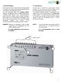
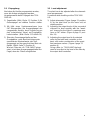
2 Vorbereitungen
Die insgesamt vier Kreuzschlitzschrauben (Bild
3/1) oben und unten am Gehäuseoberteil lösen
und dieses vorsichtig abnehmen.
Auf die Eingänge (Bild 3/2, vordere Reihe)
werden die gewünschten Satellitensignale ge-
schaltet (LNB-Signal). Der Durchschleifaus-
gang (Bild 3/3, hintere Reihe) sollte, insbeson-
dere wenn HD Transponder empfangen wer-
den, nicht genutzt werden. Alle nicht benutzten
Eingänge sollten mit einem 75-Ω-
Abschlusswiderstand abgeschlossen werden.
HINWEIS Dabei ist zu beachten, dass an allen
Eingängen ein Signalpegel von >55
dBµV anliegen muss.
Es wird empfohlen nicht durchzu-
schleifen!
2 Preparations
Loosen the in total four cross-head screws
(Figure 3/1) on the top and the bottom of the
housing upper part and remove it carefully.
The desired satellite signal is switched on the
input of the 1st channel (Figure 3/2 front row)
(LNB signal). The feed-through output (Figure
3/3, back row) should not be used. All unused
inputs should be terminated with a 75-Ω-
terminal resistance.
NOTE It has to be taken into account that a
signal level of > 55 dBµV must be
on at all inputs.
It is recommended not to feed
through.
Bild/ Figure 3
1
1
1
1
3
2

6
3 Bedienung
3.1 Programmierung
Vor Beginn der Programmierung sollte über-
prüft werden, wo sich im SAT-Bereich noch
genügend Platz für den gewünschten SAT-
Kanal befindet.
Bei der Programmierung wird die Transponder-
Frequenz genutzt (z.B. 12440 MHz), nicht die
SAT-ZF (1840 MHz)
Den benötigten Abstand zwischen einem vor-
handenen und dem neuen Kanal soll mind. 38
MHz betragen.
Falls Sie die TSM 1000 HD zusammen mit
dem Filter TSM-SAB…nutzen möchten, beach-
ten Sie bitte zuerst die Anweisung zum Aufbau
in der Bedienungsanleitung des TSM-SAB.
Das abgebildete Bild entspricht exakt dem
Aufbau, der der Vorprogammierung entspricht.
Bei der TSM 1000 HD kann zwischen drei Be-
dienmodi gewählt werden:
Auto Unter Berücksichtigung der Kanalab-
stände werden die Kanäle automatisch
ab einer Startfrequenz hintereinander
platziert. Bei Verwendung eines SAT-
Filters (z.B. TSM-SAB07) ist der Auto-
modus nicht zu empfehlen.
Hand Die Ausgangsfrequenzen können frei
gewählt werden.
Expert Dieser Modus wird nur benötigt, falls
die LO Frequenz der gewünschten Sa-
tellit nicht 9750/10600 MHz beträgt.
Zuerst werden nacheinander alle Eingangs-
frequenzen programmiert. Bei der Anzeige
des ausgewählten Platzes erscheint ein I
vor dem PL..
Danach werden alle Ausgangsfrequenzen
nacheinander programmiert.
3 Operation
3.1. Programming
First of all it is necessary to check where a free
place for the required transponder within the
SAT-range is available before programming.
For programing the SAT frequency will be used
(z.B. 12440 MHz), not the die SAT-IF (1840
MHz)
For the required distance between an existing
and the new channel should be min. 38 MHz.
If you want to use the TSM 1000 HD in combi-
nation with the TSM-SAB.. filter, please at first
note the instructions in the user manual of the
TSM-SAB.
The pictured drawing equates excact the con-
ficuration, of the pre programming.
With the TSM 1000 HD it can be selected be-
tween three operating modes.
Auto Considering channel spacing, the
channels are placed automatically in
succession from a start frequency.
Using a SAT filter (i.e. TSM-SAB07)
the automode is not recommendable.
Hand The output frequencies can be chosen
freely.
Expert The Expert modus is needed if the Lo
frequency of the satellite is not
9750/10600 MHz.
At first the input frequency will be pro-
gramed
one after another. A I for input will be dis-
played in front of PL..
After that the output frequency will be pro-
gramed one after another.

7
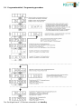
3.2 Programmierablauf / Programming procedure
Das Gerät geht nach 1,5 Minuten automatisch auf standby.
see next page

8
3.3 Einpegelung
Nachdem die Kanäle programmiert wurden,
muss die Anlage eingepegelt werden.
Vorgehensweise beim Einpegeln der TSM-
1000 HD:
1) Pegelsteller (Bild 4 Seite 11 Position 9) für
Gesamtpegel auf mittlere Position stellen.
2) Mit Hilfe eines Spektrumanalysers bzw.
SAT-Messgerätes die Ausgangspegel der
umgesetzten Kanäle, durch Anpassung an
den "schwächsten" Kanal, auf Pegelgleich-
heit einstellen. (Bild 4 Seite 11 Position 14)
3) Über den Gesamtpegelsteller auf der
Grundplatine, unter Berücksichtigung der
spezifizierten Maximalwerte, den Aus-
gangspegel auf den gewünschten Wert ein-
stellen. (Bild 4 Seite 11 Position 9)
Wird ein Filter wie z.B. TSM-SAB07 einge-
setzt, ist mit dem Ausgangspegelsteller der
Pegel, dem des Filters anzugleichen
3.3 Level adjustment
The plant has to be adjusted after the channels
were programmed.
Procedure while levelling out the TSM 1000
HD:
1) Adjust attenuator (Figure 4 page 11 position
9) for the total level (on the basic unit) at
middle position.
2) Adjusting the output levels of the converted
channels to level equality with the "weak-
est" channel by the help of a spectrum ana-
lyser or SAT-meter. (Figure 4 page 11 posi-
tion 14)
3) Adjusting the output level to the desired
value by the total level controller on the
basic unit under consideration of the speci-
fied maximum values. (Figure 4 page 11
position 9)
Using a filter i.e. TSM-SAB07 the level
need to be adjust to the level of the filter by
the output level controller.

9
3.4 Funktionen im Service-Menü
3.4.1 Wiederherstellung der Grundeinstel-
lung
Im Standby-Modus (●) drücken Sie die Tasten
OK, + und – zur gleichen Zeit, bis der Punkt
erlischt. Nach dem Loslassen der Tasten er-
scheint rst im Display. Um die Routine zu star-
ten, bestätigen Sie mit OK. Nun werden die
Funktionen des TSM-1000 überprüft und die
werkseitigen Grundeinstellungen wieder her-
gestellt. Die Routine ist abgeschlossen, wenn
End erscheint.
Danach springt das Gerät automatisch in den
Standby-Modus zurück.
3.5 Functions of the service menu
3.5.1 Restoration of basic setting
When in Standby mode (●), push the buttons
OK, + and – at the same time until the dot dis-
appears. After you have released the buttons,
the display shows rSt. The start of test routine
is acknowledged by pressing the OK button.
Now the functions of the TSM-1000 are
checked and the factory set pre-programmed
settings are be restored.
The routine is finished when End is displayed.
Hereafter, the unit automatically jumps back to
the Standby mode.

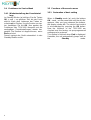
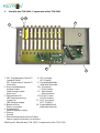
4 Bauteile des TSM 1000 / Components of the TSM 1000
1 SAT-Signaleingang (Kanal 1) 8 LED-Anzeige
(vordere Reihe) LED-Display
SAT-Signal input (Channel 1) 9 Gesamtpegelsteller
(front row) total level controller
2 Durchschleifausgang 10 + (Plustaste)
(hintere Reihe) + (Plus button)
Feed-through output 11 − (Minustaste)
(back row) − (Minus button)
3 Steckbrücken für 12 OK (OK-Taste)
LNB-Speisespannung OK (OK-button)
Jumper for 13 OUT (Ausgang)
LNB feeding voltage OUT (Output)
4 Netzanschluss 14 Pegelsteller/Kanal
Mains connection Attenuator/channel
5 Schaltnetzteil
Switching power supply
6 Erdung
Ground
7 Stromversorgungsanschluss Platine
Power supply connection circuit board
Bild/Figure 4 Bauteile des TSM 1000 / Components of the TSM 1000
K
anal/Channel 1
2
3
4
5
6
7
8
9
10
1
4
8
13
12
11
6
14
8
7
9
1
2
3
4
5
10

11
5 Technische Daten/ Technical Data
5.1 Eingangsbereich / Input
Eingangsfrequenz/ Input frequency range ................................. 10700 - 12750 MHz
Eingangspegel/ Input level ................................................................. 52 ... 75 dBµV
Frequenzabstimmung/ Frequency Stepps ................................ 1 MHz Schritte/steps
LNB-Speisung/ LNB feeding voltage ........................................................................ .
................................................12 V= / 250 mA pro Eingang/max. gesamt 500 mA
................................................. max. 12 V= / 250 mA per input/max. 500 mA total
Oszillatorspannung am Eingang/ Spurious emission ................................... -63 dBm
Zwischenfrequenz/ Intermediate frequency ................................................. 480 MHz
Durchschleifausgang/ Line output .............................................. 10700 - 12750 MHz
Durchschleifausgang Dämpfung/ Line output attenuation ........................ max. -3 dB
Anschlüsse/ Connections ......................................... F-Buchse/75 Ω / F-socket/75 Ω
5.2 Ausgangsbereich/ Output
Ausgangsfrequenzbereich/ Output frequency range .................. 10700 - 12750 MHz
Frequenzabstimmung/ Frequency steps .................................. 1-MHz-Schritte/steps
Oszillatorunterdrückung/ Oscillator suppression ........................................... > 20 dB
Nebenwellenabstand/ Spurious emission ...................................................... ≥ 26 dB
Pegelsteller/ Variable attenuator ..................................................................... -20 dB
Ausgangspegel/ Output level ................................................................ typ.88 dBµV
5.3 Allgemeine Daten/ General data
Betriebsspannung/ Operating voltage ................................ 190 ... 260 V~ / 50/60 Hz
Leistungsaufnahme/ Power consumption ............................................. max. 40 Watt
Umgebungstemperatur/ Ambient temperature ...................................... 0° bis +50°C
Maße (H x B x T)/ Dimensions (h x w x d) ................................... 195 x 380 x 80 mm
Gewicht/ Weight ............................................................................... 3 kg (Netto/ net)

Polytron-Vertrieb GmbH
Postfach 10 02 33
75313 Bad Wildbad
Zentrale/Bestellannahme
H.Q. Order department + 49 (0) 70 81/1702 - 0
Technische Hotline
Technical hotline + 49 (0) 70 81/1702 - 12
Telefax + 49 (0) 70 81) 1702 - 50
Internet http://www.polytron.de
eMail info@polytron.de
Technische Änderungen vorbehalten
Subject to change without prior notice
Copyright © Polytron-Vertrieb GmbH
-
 1
1
-
 2
2
-
 3
3
-
 4
4
-
 5
5
-
 6
6
-
 7
7
-
 8
8
-
 9
9
-
 10
10
-
 11
11
-
 12
12


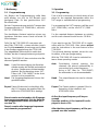
POLYTRON TSM 1000 HD PolySelect SAT IF channel converter compact HD Bedienungsanleitung
- Kategorie
- Ladegeräte
- Typ
- Bedienungsanleitung
in anderen Sprachen
Verwandte Papiere
-
POLYTRON TSM 1000 PolySelect SAT IF channel converter compact Bedienungsanleitung
-
-
-
-
-
-
-
-
-