
1
TSM 32 HD
SAT ZF Konverter
SAT IF Converter
Bedienungsanleitung
Operating manual
0902401 V1

2
Inhaltsverzeichnis
1. Montage- und Sicherheitshinweise 3
2. Beschreibung 5
3. Lieferumfang 5
4. Funktionselemente 5
5. Montage 6
6. Programmierung mittels Drehknopf 6
6.1 Das Menü „OVERVIEW“ 6
6.2 Automatischer Scan Eingang 1 „COPY INPUT 1“ ________________________________ 7
6.3 Manuelle Programmierung „INPUT SAT 1 - 4“ __________________________________ 8
6.4 Programmierung der Ausgangssignale „OUTPUT“ ______________________________ 8
6.5 Erweiterte Einstellungen „ADVANCED“ _______________________________________ 9
6.6 Laden der Einstellung von der SD-Karte „LOAD SD PRESET“ _____________________ 9
6.7 Sichern der Einstellung auf der SD-Karte „SAVE SD PRESET“ ____________________ 9
6.8 Aktivierung Passwortschutz „Exit“ ___________________________________________ 9
7. Technische Daten ____________________________________________________________ 18
8. Vorlage Programmiertabelle __________________________________________________ 19

3
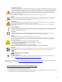
1. Montage- und Sicherheitshinweise
Bitte beachten Sie die nachfolgenden Sicherheitshinweise, um jegliche Risiken für Personen auszuschließen und Beschädigungen
am Gerät zu vermeiden sowie einen Beitrag zum Umweltschutz zu leisten.
Wichtige Hinweise
Bitte lesen Sie die Bedienungsanleitung der Geräte aufmerksam durch bevor Sie diese in Betrieb nehmen! Die Anleitung enthält wichtige
Informationen zur Installation, Umgebungsbedingungen sowie Wartung und Service am Gerät! Bewahren Sie die Bedienungsanleitung für den
späteren Gebrauch auf. Alle Bedienungsanleitungen finden sie auf unserer Website unter:
https://polytron.de/index.php/de/service/bedienungsanleitungen
Bestimmungsgemäßer Gebrauch
Verwenden Sie das Gerät nur an den zulässigen Betriebsorten, unter den zulässigen Umgebungs-bedingungen sowie zu den
in der Bedienungsanleitung beschriebenen Zweck.
Liegen zum beabsichtigten Gebrauch (z.B. Betriebsort, Umgebungsbedingungen) keine Informationen vor oder enthält die
Betriebsanleitung keine entsprechenden Hinweise, müssen Sie sich an den Hersteller dieses Gerätes wenden um
sicherzustellen, dass das Gerät eingebaut werden kann. Erhalten Sie vom Hersteller keine Information hierzu, darf das Gerät
nicht in Betrieb genommen werden.
Transport
Überprüfen Sie die Verpackung und das Gerät nach Erhalt sofort auf Transportschäden. Nehmen Sie ein beschädigtes Gerät
nicht in Betrieb.
Der Transport des Gerätes am Netzkabel ist nicht zulässig, da dies zu einer Beschädigung des Netzkabels oder der
Zugentlastung führen kann. Durch übermäßige Belastung (z.B. Fall, Stoß, Vibration) können Isolierungen beschädigt werden,
die dem Schutz vor Netzspannungen dienen.
Achtung
Die auf dem Gerät angegebene Nennspannung muss mit der örtlichen Netzspannung übereinstimmen. Beim Betrieb von
Geräten mit Schutzklasse I ist der Anschluss an Netzsteckdosen mit Schutzleiteranschluss zwingend erforderlich. Die
Hinweise zum Betrieb des Gerätes sind zu beachten.
Erdung und Potentialausgleich
Vor der Erstinbetriebnahme muss die Erdung hergestellt und der Potentialausgleich durchgeführt werden.
Gemäß der aktuell gültigen Fassung der EN 60728-11 müssen koaxiale Empfangs- und Verteilanlagen den
Sicherheitsanforderungen bezüglich Erdung, Potentialausgleich etc. entsprechen, auch wenn das Gerät ausgebaut wird.
Sonst können Schäden am Produkt, ein Brand oder andere Gefahren entstehen. Zusätzlich kann der Erdungsanschluss am
Gerät genutzt werden. Geräte im Handbereich sind untereinander in den Potentialausgleich einzubinden. Ein Betrieb ohne
Schutzleiteranschluss, Geräteerdung oder Potentialausgleich ist nicht zulässig. Bei Beschädigung ist das Gerät außer Betrieb
zu nehmen.
Die elektrische Anlage zur Stromversorgung des Gerätes, z.B. Hausinstallation muss Schutzeinrichtungen gegen überhöhte
Ströme, Erdschlüsse und Kurzschlüsse enthalten.
Befolgen Sie auch alle anwendbaren nationalen Sicherheitsvorschriften und Normen.
Anschlusskabel
Alle Anschlusskabel müssen stolperfrei mit einer Schlaufe verlegt werden, damit das Kondenswasser- und/oder bei
Schwitzwasserbildung kein Wasser ins Gerät läuft sondern auf den Boden tropft.
Aufstellungsort wählen
Planen sie den Montageort so, dass Kinder nicht am Gerät und dessen Anschlüssen spielen können. Die Montage des
Gerätes sollte nur auf eine feste, ebene und möglichst brandresistente Oberfläche erfolgen. Die in der Bedienungsanleitung
angegebene Betriebsposition der Geräte beachten. Starke Magnetfelder in der Nähe vermeiden. Zu starke Hitzeeinwirkung
oder Wärmestau haben einen negativen Einfluss auf die Lebensdauer. Nicht direkt über oder in der Nähe von
Heizungsanlagen, offenen Feuerquellen o.ä. Wärmequellen montieren, wo das Gerät Hitzestrahlung oder Öldämpfen
ausgesetzt ist. Lüftergekühlte und passiv gekühlte Geräte so montieren, dass die Luft ungehindert durch die unteren
Belüftungsschlitze angesaugt wird und die Wärme an den oberen Lüftungsschlitzen austreten kann. Für freie Luftzirkulation
sorgen, Lüftungsschlitze dürfen nicht abgedeckt werden. Keine Gegenstände auf dem Gerät abstellen. Die Montage in
Nischen und die Abdeckung des Montageortes, z.B. durch Vorhänge ist nicht zulässig. Zur Vermeidung von Stauwärme ist
unbedingt die richtige Einbaulage zu beachten und allseitige, freie Umlüftung gemäß den Angaben in der Bedienungsanleitung
zu gewährleisten! Bei Schrankmontage muss eine ausreichende Luftkonvektion möglich sein, die sicherstellt, dass die
maximal zulässige Umgebungstemperatur des Gerätes eingehalten wird.
Feuchtigkeit
Die Geräte besitzen keinen Schutz gegen Wasser und dürfen daher nur in trockenen Räumen betrieben und angeschlossen
werden. Tropf-, Spritzwasser und hohe Luftfeuchtigkeit schaden dem Gerät. Bei Kondenswasserbildung warten, bis die
Feuchtigkeit abgetrocknet ist. Betriebsumgebung laut spezifizierter IP-Schutzklasse wählen.
Wärme
Gehäuseteile in der Nähe von Kühlrippen und Kühlrippen selber können sehr heiß werden. Daher sollten Sie diese Teile nicht
berühren.

4
Installations- und Servicearbeiten
Das Gerät darf ausschließlich von sachverständigen Personen (gemäß EN 62368-1) oder von Personen, die durch
Sachverständige unterwiesen wurden, entsprechend den Regeln der Technik, installiert und betrieben werden.
Wartungsarbeiten dürfen nur von qualifiziertem Servicepersonal durchgeführt werden. Vor Beginn der Servicearbeiten die
Betriebsspannung abschalten und gegen Wiedereinschalten sichern. Der Netzstecker dient im Service- und Gefahrenfall als
Trennvorrichtung von der Netzspannung und muss deshalb jederzeit erreichbar und benutzbar sein. Um die
Störstrahlsicherheit zu garantieren, müssen sämtliche Geräteabdeckungen nach Öffnen wieder fest verschraubt werden.
Sicherungen werden nur von autorisiertem Fachpersonal gewechselt. Es dürfen nur Sicherungen des gleichen Typs
eingesetzt werden.
Reparaturen
Reparaturen dürfen nur vom Hersteller ausgeführt werden. Durch unsachgemäße Reparaturen können erhebliche Gefahren
für den Benutzer entstehen. Bei Funktionsstörungen muss das Gerät vom Netz getrennt und autorisiertes Fachpersonal
hinzugezogen werden. Gegebenenfalls ist das Gerät an den Hersteller einzusenden.
Gewitter
Laut EN 60728-Teil 1 Sicherheitsanforderungen, aufgrund erhöhter Blitzschlaggefahr keine Wartungs- und/oder
Installationsarbeiten bei Gewitter am Gerät oder an der Anlage vornehmen.
Durch hohe Überspannungen (Blitzeinschlag, Überspannungen im Stromnetz) können Isolierungen beschädigt werden, die
dem Schutz vor Netzspannung dienen.
Umgebungstemperatur
Die in den technischen Daten angegebenen zulässigen Umgebungstemperaturen müssen für Betrieb und Lagerung
eingehalten werden, auch wenn sich die klimatischen Bedingungen durch äußere Einflüsse (Sonneneinstrahlung etc.)
verändern. Durch Überhitzung des Gerätes können Isolierungen beschädigt werden, die der Isolation der Netzspannung
dienen.
Abschluss / Terminierung
Nicht benutzte koaxiale Anschlüsse sind mit 75 Ohm-Abschlusswiderständen abzuschließen. Bei DC versorgten Anschlüssen
erst für eine DC Spannungsentkopplung sorgen bzw. 75 Ohm Abschlusswiderstände verwenden mit integrierter DC
Entkopplung.
Achtung
Diese Baugruppe enthält ESD-Bauteile! (ESD = Elektrostatisch empfindliches Bauteil)
Eine elektrostatische Entladung ist ein elektrischer Stromimpuls, der, ausgelöst durch große Spannungsdifferenz, auch über
ein normalerweise elektrisch isolierendes Material fließen kann.
Um die Zuverlässigkeit von ESD-Baugruppen gewährleisten zu können, ist es notwendig, beim Umgang damit die wichtigsten
Handhabungsregeln zu beachten:
» Nur an elektrostatisch geschützten Arbeitsplätzen (EPA) diese Bauteile verarbeiten!
» Auf ständigen Potentialausgleich achten!
» Personenerdung über Handgelenk- und Schuherdung sicherstellen!
» Elektrostatisch aufladbare Materialien wie normales PE, PVC, Styropor, etc. vermeiden!
» Elektrostatische Felder >100 V/cm vermeiden!
» Nur gekennzeichnete und definierte Verpackungs- und Transportmaterialien einsetzen!
Schäden durch fehlerhaften Anschluss und/oder unsachgemäße Handhabung sind von jeglicher Haftung
ausgeschlossen.
Recycling
Unser gesamtes Verpackungsmaterial (Kartonagen, Einlegezettel, Kunststoff-Folien und -beutel) ist vollständig recyclingfähig.
Die Geräte sind nach ihrer Verwendung entsprechend den aktuellen Entsorgungsvorschriften Ihres
Landkreises/Landes/Staates als Elektronikschrott einer geordneten Entsorgung zuzuführen.
WEEE-Reg.-Nr. DE 51035844
Garantiebedingungen
Es gelten die allgemeinen Geschäftsbedingungen der Polytron-Vertrieb GmbH. Diese finden Sie auf unserer Website unter:
https://polytron.de/index.php/de/unternehmen/agbs
Hiermit erklärt Polytron-Vertrieb GmbH, dass das Produkt TSM 32 HD der Richtlinie 2014/53/EU entspricht. Die
vollständige EU-Konformitätserklärung ist unter folgender Internetadresse verfügbar:
https://polytron.de/index.php/de/service/deklarationen.
ALLGEMEINE HINWEISE ZUR BEDIENUNGSANLEITUNG
Alle Parameterangaben sind lediglich beispielhaft.
Technisch realisierbare Parameter sind frei wählbar.
Menüansichten können je nach Software-Stand leicht variieren; die Bedienbarkeit ändert sich dadurch nicht.
Die Bilder in dieser Anleitung dienen lediglich als Illustrationen.
§

5
1
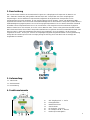
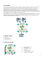
2. Beschreibung
Der SAT-Konverter TSM 32 HD konvertiert SAT-Signale von 4 Eingängen auf Frequenzen im Bereich von
290 - 2340 MHz. Dabei wird jeder gewünschte DVB-S/S2 SAT-Transponder aus seiner ursprünglichen
Frequenzlage in ein frei wählbares Frequenzraster umgesetzt. Nicht gewünschte Transponder sind im
Ausgangssignal nicht mehr enthalten. An den SAT-Eingängen können Quattro-, Quad- oder Wideband-LNBs
angeschlossen werden. Der TSM 32 HD setzt 32/64 beliebige DVB-S oder DVB-S2 Transponder (QPSK/ 8PSK) in
32/64 beliebige Ausgangsfrequenzen im um. Der Ausgangsfrequenzbereich ist von 290 bis 2340 MHz individuell
einstellbar. Dieser Frequenzbereich kann in ein vorhandenes, SAT-taugliches Koaxial-Verteilnetz eingespeist
werden. Hierbei ist es nicht relevant, ob es sich um ein Netz mit Stern-, Baum- oder gemischter Struktur handelt.
Die Teilnehmer können alle auf den Transpondern befindlichen Programme mit einem handelsüblichen DVB-S/S2
Receiver oder TV-Gerät mit integriertem DVB-S/S2 Tuner empfangen. Es ist unerheblich, ob die einzelnen
Programme in HDTV-, als Pay-TV- oder als frei empfangbare Signale ausgestrahlt werden. Die Programmierung
erfolgt über den Drehknopf am Gerät. Im Display erfolgt die Führung durch das Menü und die Anzeige der
eingestellten Parameter.
3. Lieferumfang
1 x TSM 32 HD
1 x Steckernetzteil
1 x Kurzanleitung
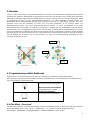
4. Funktionselemente
1 SAT-Eingänge SAT 1 - SAT 4
2 Erdungsklemme
3 Netzteil-Anschluss
4 Slot SD-Karte
5 HF-Ausgang - F-Buchse
6 HF-Testport -30 dB - F-Buchse
7 Drehknopf zur Navigation
4
5
6
2
7
3

6
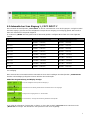
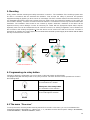
5. Montage
Lesen sie zuerst die Montage- und Sicherheitshinweise in Abschnitt 1. Die Installation des Empfangssystems gemäß
der Norm IEC 60728-11 gewährleistet die Sicherheit des Personals und verhindert, dass Geräte durch Blitzschlag
oder andere Überspannungsquellen beschädigt werden. Der SAT-Konverter muss an einer nicht brennbaren Wand
in waagerechter Position mit den SAT-Eingangs-Anschlüssen von oben zugänglich montiert werden. Zur
Befestigung werden Stahlschrauben benötigt. Die Schrauben sind nicht im Lieferumfang enthalten. Der SAT-
Konverter muss nach der Installation von oben, vorn und unten mindestens 15 cm Freiraum haben. Die
Belüftungsschlitze dürfen nicht durch Gegenstände bedeckt werden, da sonst die Belüftung des Gerätes
beeinträchtigt wird und Schäden im Gerät verursachen kann. Verbinden Sie alle notwendigen HF-Kabel mit den
entsprechenden Ein- und Ausgängen. Optional kann eine SD-Karte im SD-Kartenslot installiert werden. Von dieser
kann eine bestehende Konfiguration auf den Konverter geladen oder die vorhandene Konfiguration auf der SD-Karte
gesichert werden. Der SAT-Konverter wird von einem externen 12V-Steckernetzteil mit Strom versorgt. Schließen
Sie das Netzteil des Konverters erst an das Stromnetz an, wenn alle Verbindungskabel vollständig am SAT-
Konverter angeschlossen sind.
6. Programmierung mittels Drehknopf
Änderungen an der Grundkonfiguration können nur via Drehknopf und Display vorgenommen werden.
Die Programmierung mit dem Drehknopf ist sehr einfach und übersichtlich. Die Grundfunktionen für die Bedienung
sind in der folgenden Tabelle dargestellt:
Drücken des Drehknopf für 2s
Übersichts-Menü wird geladen
Kurzes Drücken des Drehknopf
Bestätigung der Auswahl
Drehen des Drehknopf
Scrollen durch die Auswahl
6.1 Das Menü „Overview“
Um das Menü aufzurufen, muss der Drehknopf für 2 Sekunden gedrückt werden. Im Menü kann man dann zwischen
den Programmierpunkten „COPY INPUT 1“, „INPUT SAT 1 - 4“, „OUTPUT“ und den gerätespezifischen
Einstellungen „ADVANCED“, „LOAD SD PRESET“, „SAVE SD PRESET“, „EXIT“ wählen.
15 cm
15 cm
= Wärmestau !!!
15 cm

7
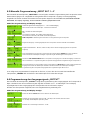
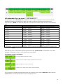
6.2 Automatischer Scan Eingang 1 „COPY INPUT 1“
Durch Anwahl des Menüpunktes „COPY INPUT 1“ wird ein automatischer Scan des Einganges 1 ermöglicht. Dabei
wird der Eingang 1 gescannt und die verfügbaren Transponder am Ausgang zur Verfügung gestellt. Die Anzahl ist
dabei auf maximal 32 Transponder begrenzt.
Im Untermenü „MODE“ wird der gewünschte SCAN-Mode gewählt. Verfügbare Modi finden Sie in der folgenden
Tabelle:
MODE
INPUT SIGNAL
OUTPUT SIGNAL
OFF
- (manuelle Programmierung nötig)
- (manuelle Programmierung nötig)
Qlo Qlo
QUATTRO LOW
(950 MHz … 1950 MHz)
QUATTRO LOW
(950 MHz … 1950 MHz)
Qlo Wlo
QUATTRO LOW
(950 MHz … 1950 MHz)
WIDEBAND LOW
(290 MHz … 1290 MHz)
Wlo Qlo
WIDEBAND LOW
(290 MHz … 1290 MHz)
QUATTRO LOW
(950 MHz … 1950 MHz)
Wlo Wlo
WIDEBAND LOW
(290 MHz … 1290 MHz)
WIDEBAND LOW
(290 MHz … 1290 MHz)
Qhi Qhi
QUATTRO HIGH
(1100 MHz … 2150 MHz)
QUATTRO HIGH
(1100 MHz … 2150 MHz)
Qhi Whi
QUATTRO HIGH
(1100 MHz … 2150 MHz)
WIDEBAND HIGH
(1290 MHz … 2340 MHz)
Whi Qhi
WIDEBAND HIGH
(1290 MHz … 2340 MHz)
QUATTRO HIGH
(1100 MHz … 2150 MHz)
Whi Whi
WIDEBAND HIGH
(1290 MHz … 2340 MHz)
WIDEBAND HIGH
(1290 MHz … 2340 MHz)
W W
WIDEBAND
(290 MHz … 2340 MHz)
WIDEBAND
(290 MHz … 2340 MHz)*
* ACHTUNG: In diesem Mode wird das gesamte Band gescannt. Am Ausgang stehen die ersten 32 Transponder
zur Verfügung.
Nach Auswahl des SCAN-Mode wird der automatische Scan durch bestätigen des Menüpunktes „START SCAN“
aktiviert. Die Bestätigung erfolgt durch kurzes Drücken des Drehknopfes.
Ablauf der Programmierung und Display-Anzeige:
Ist es nötig die gefundenen Transponder zu ändern, so kann dies im Menü „Input SAT 1- 4“ unter dem Punkt
„INPUT SAT 1“ erfolgen. Hier werden die Transponder aus den Scan angezeigt.
Scan der verfügbaren Transponder am Eingang 1
Auswahl des Such-Modes gemäß Tabelle und Starten des Scan-Vorganges
Anzeige Scan-Vorgang, Dauer ca. 30 Sekunden
Scan-Abschluss, Anzeige der Anzahl der gefundenen Transponder

8
6.3 Manuelle Programmierung „INPUT SAT 1 - 4“
Durch Anwahl des Menüpunktes „INPUT SAT 1 - 4“ erfolgt die manuelle Programmierung der Transponder. Dabei
werden die Eingänge 1 bis 4 angewählt und die gewünschten Transponder eingangs- und ausgangsseitig
eingestellt. Die Anzahl ist dabei auf maximal 32 Transponder begrenzt. Wird die Nachricht „MAXIMUM TRANSP.
REACHED“ am Display angezeigt, ist die maximale Umsetzungskapazität erreicht.
Ablauf der Programmierung und Display-Anzeige:
Ist es nötig einen programmierten Transponder zu löschen, so kann dies durch Anwahl des betreffenden
Transponders „TRANSP: 17“ und Drücken des Drehknopfes für 3 Sekunden erfolgen.
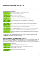
6.4 Programmierung der Ausgangssignale „OUTPUT“
Durch Anwahl des Menüpunktes „OUTPUT“ erfolgt die Programmierung des Ausgangspegels der Transponder in
dBµV. Zusätzlich kann eine Vorentzerrung des Signales im Bereich von 0 - 15 dB erfolgen. Der im Display
angezeigte Wert ist der Ausgangspegel des Transponders mit der höchsten Frequenz.
Werden viele Transponder umgesetzt, kann eine Pegelreduzierung notwendig sein.
Ablauf der Programmierung und Display-Anzeige:
Anwahl des gewünschten Eingangs SAT 1 … SAT 4 und Bestätigung
durch kurzes Drücken des Drehknopfes Untermenü ist aktiviert
DC = Auswahl der LNB-Schaltsignale:
OFF,
13V (Vertikal Low Band), 13V+TONE (Vertikal High Band)
18V (Horizontal Low Band), 18V+TONE (Horizontal High Band)
ADD Transponder = Aktivierung des Untermenüs zur Programmierung der Transponder
Eingabe der Eingangs- und Ausgangsfrequenz des Transponders zwischen 290 MHz und 2340 MHz
Eingabe der Bandbreite 1 - 64 MHz (1 MHz Schritte), danach wird der Eingangspegel des Transponders
angezeigt
Wenn alle Eingaben für Transponder 1 erfolgt sind, bitte zum Menüpunkt TRANSP: 1 scrollen und diesen
durch Drücken des Drehknopfes bestätigen Speicherung der Einstellungen für Transponder 1
Anwahl von ADD TRANSPONDER weitere Transponder vom Eingang SAT 1 werden hinzugefügt - maximal 32
über 4 SAT-Ebenen - Programmierung aller Transponder erfolgt gemäß der Programmierung für Transponder 1
Zur Programmierung von Transpondern weiterer SAT-Eingänge zu INPUT SAT 1 scrollen und den gewünschten
Eingang durch Drehen des Drehknopfes anwählen und durch Drücken des Drehknopfes bestätigen -
Programmierung aller Transponder erfolgt gemäß der Programmierung für INPUT SAT 1
Anwahl des Menüs OUTPUT durch kurzes Drücken des Drehknopfes
Definition des Ausgangspegels im Bereich 89 - 112 dBµV (1 dB Schritte) oder fixe Anwahl
von 70 dBµV oder 83 dBµV für optische Systeme
Definition der Vorentzerrung im Bereich 0 - 15 dB

9
6.5 Erweiterte Einstellungen „ADVANCED“
Durch Anwahl des Menüpunktes „ADVANCED“ können allgemeine Einstellungen am Gerät erfolgen und
gerätspezifische Daten ausgelesen werden.
Ablauf der Programmierung und Display-Anzeige:
LANGUAGE = Sprachwahl (Englisch, Italienisch, Spanisch oder Französisch)
FW VERSION = Anzeige der Firmenware-Version des Gerätes
SERIAL NUMBER = Anzeige der Seriennummer des Gerätes
FORMAT CARD = Formatierung der SD-Karte
6.6 Laden der Einstellung von der SD-Karte „LOAD SD PRESET“
Durch Anwahl des Menüpunktes „LOAD SD PRESET“ kann eine gesicherte Einstellung von der SD-Karte auf das
Gerät geladen werden.
Ablauf der Programmierung und Display-Anzeige:
6.7 Sichern der Einstellung auf der SD-Karte „SAVE SD PRESET“
Durch Anwahl des Menüpunktes „SAVE SD PRESET“ kann eine Einstellung auf der SD-Karte gespeichert werden.
Es wird empfohlen nach jeder Änderung an der Einstellung eine Sicherung auf der SD-Karte vorzunehmen.
In diesem Menü ist es auch möglich alle gesicherten Einstellungen von der SD-Karte zu löschen. Dazu mit dem
Drehknopf das Untermenü „DELETE ALL“ anwählen und durch Drücken des Drehknopfes bestätigen.
Ablauf der Programmierung und Display-Anzeige:
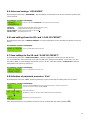
6.8 Aktivierung Passwortschutz „Exit“
Durch Anwahl des Menüpunktes „Exit“ kann das Einstellmenü verlassen und ein Passwort-Zugang angelegt
werden.
Ablauf der Programmierung und Display-Anzeige:
Falls das Passwort des Gerätes nicht verfügbar ist, kann der Zugang zum Gerät mit dem Master-Passwort 50
erfolgen.
Anwahl des Menüs ADVANCED durch kurzes Drücken des Drehknopfes
Laden einer Konfiguration von der SD-Karte
Sichern einer Konfiguration von der SD-Karte
Anwahl des Menüs Exit durch kurzes Drücken des Drehknopfes - Aktivierung des
Passwortschutzes durch Anwahl von LOCK
Eingabe des Passwortes
ACHTUNG - Gerät wird heruntergefahren und mit Passwortschutz neu gestartet!
Deaktivierung des Passwortschutzes

10
Contents
1. Mounting- and safety instructions 11
2. Description 13
3. Delivery content 13
4. Function elements 13
5. Mounting 14
6. Programming via rotary button 14
6.1 The menu “OVERVIEW“ 14
6.2 Automatically scan input 1 “COPY INPUT 1“ __________________________________ 15
6.3 Manually programming “INPUT SAT 1 - 4“ ____________________________________ 16
6.4 Programming of the output signals “OUTPUT“ ________________________________ 16
6.5 Advanced settings “ADVANCED“____________________________________________ 17
6.6 Load settings from the SD card "LOAD SD PRESET“ ___________________________ 17
6.7 Save settings to the SD card “SAVE SD PRESET“ ______________________________ 17
6.8 Activation of password protection “Exit“ _____________________________________ 17
7. Technical data _______________________________________________________________ 18
8. Template programming table _________________________________________________ 19

11
1. Mounting and safety instructions
Please observe the following safety instructions in order to prevent any risks for persons and/or damage to the device, as well as to
contribute to environmental protection.
Important instructions
Please read the operating instructions for the device(s) carefully before putting into operation! The instructions contain important information on
installation, environmental conditions, service and maintenance. Save the operating instructions for later use. All operating instructions can be
found on our website at: https://polytron.de/index.php/en/services/operating-manuals
Approved use
Use the device only at the permissible operating locations, under the permissible environmental conditions and for the purpose
described in the operating instructions. If there is no information about the intended use (e.g. operating location, environmental
conditions) or if the operating instructions do not contain any relevant information, you must contact the manufacturer of this
device to ensure that the device can be installed. If you do not receive any information from the manufacturer, the device must
not be put into operation.
Transport
Please check the packaging and the device for damages in shipment immediately upon receipt. Do not put a damaged device
into operation.
Transporting the device by the power cord is not permitted as this can damage the power cord or the strain relief. Insulation
that serves to protect against mains voltages can be damaged by excessive loads (e.g. fall, shock, vibration).
Attention
The rated voltage on the device must correspond with the mains voltage to be used. When operating devices with protection
class I, connection to power sockets with a protective conductor connection is mandatory. The instructions for operating the
device must be observed.
Grounding and potential equalisation
Please establish grounding and perform potential equalisation before initial startup. According to the currently valid version of
EN 60728-11, coaxial receiving and distribution systems must meet the safety requirements with regard to earthing,
equipotential bonding etc, even if the device is removed. Otherwise, damage to the product, fire, or other dangers can occur.
In addition, the earth connection on the device can be used. Other devices within touching distance are to be integrated in the
equipotential bonding. Operation without a protective conductor connection, device grounding or equipotential bonding is not
permitted. If damaged, the device must be taken out of operation.
The electrical system for powering the device, e.g. house installations must contain protective devices against excessive
currents, earth faults and short circuits. Follow all applicable national safety regulations and standards.
Connection cables
Always install the connection cables with a loop so that condensed and/or splashing water cannot run into the device.
Select installations site
Plan the installation location so that children cannot play with the device and its connections. The device should only be
installed on a solid, flat and most of all fire-resistant surface. Observe the operation position of the devices specified in the
operating instructions. Avoid strong magnetic fields in the surroundings. Too strong a heat effect or accumulation of heat will
have an adverse effect on the durability. Don't mount directly over or near heating systems, open fire sources or the like,
where the device is exposed to heat radiation or oil vapours. Mount fan-cooled and passively cooled devices so that the air
can be sucked in unhindered through the lower ventilation slots and heat can escape through the upper ventilations slots.
Ensure free air circulation, ventilation slots must not be covered. Do not place any objects on the devices. Installation in
recesses, alcoves etc and covering the installation site, e.g. through curtains is not allowed. To avoid heat build-up, the correct
installation position must be observed and all-round, free ventilation must be ensured in accordance with the information in the
operating instructions! When installing the cabinet, sufficient air convection must be possible to ensure that the maximum
permissible ambient temperature of the device is maintained.
Moisture
The devices have no protection against water and may therefore only be operated and connected in dry rooms.
Dripping/splashing water and high humidity damage the device. If there is condensation, wait until the device is completely dry.
Select the operating environment according to the specified IP protection class.
Heat
Housing parts near cooling fins and cooling fins themselves can get very hot. Therefore, you should not touch these parts.

12
Mounting and service work
The device may only be installed and operated by qualified persons (in accordance with EN 62368-1) or by persons who have
been instructed by experts in accordance with the rules of technology. Maintenance work may only be carried out by qualified
service personnel. Before starting the service work, switch off the operating voltage and secure it against being switched on
again. In the event of service or danger, the mains plug serves as a disconnect device from the mains voltage and must
therefore be accessible and usable at all times. In order to guarantee interference immunity, all device covers must be
screwed tight again after opening.
Fuses are only to be changed by authorised specialists. Only fuses of the same type may be used.
Repairs
Repairs may only be carried out by the manufacturer. Improper repairs can pose significant risks to the user. In the event of
malfunctions, the device must be disconnected from the mains and authorised specialist personnel must be consulted. If
necessary, the device must be sent to the manufacturer.
Thunderstorm
According to EN 60728 part 1 safety requirements, due to increased risk of lightning, maintenance and / or installation work
should not be carried out during thunderstorms on the device or the system.
High overvoltages (lightning strikes, overvoltages in the power grid) can damage insulation that serves to protect against
mains voltage.
Ambient temperature
The permissible ambient temperatures specified in the technical data must be observed for operation and storage, even if the
climatic conditions change due to external influences (solar radiation etc.). Overheating the device can damage the insulation
that serves to isolate the mains voltage.
Termination
Unused coaxial connections should be terminated with 75 Ohm terminating resistors. For DC-supplied connections, DC
voltage decoupling must be used or use 75 Ohm terminating resistors with integrated DC decoupling.
Attention
This module contains ESD components! (ESD = Electrostatic Sensitive Device).
An electrostatic discharge is an electrical current pulse, which can flow through an electrically insulated material, when
triggered by a large voltage difference. To ensure the reliability of ESD components, it is necessary to consider their most
important handling rules:
» Pay attention permanently to potential equalisation (equipotential bonding)!
» Use wrist straps and approved footwear for personnel grounding!
» Avoid electrostatically chargeable materials such as normal PE, PVC, polystyrene!
» Avoid electrostatic fields >100 V/cm!
» Use only labeled and defined packing and transportation materials!
Damage caused by faulty connections and/or improper handling are excluded from any liability.
Recycling
All of our packaging materials (packaging, identification sheets, plastic foil and bags) are fully recyclable. The devices are to
be disposed of properly according to the current disposal regulations of your district/country/state as electronic scrap.
WEEE-Reg.-Nr. DE 51035844
Guarantee conditions
The general terms and conditions of Polytron-Vertrieb GmbH apply. The general terms and conditions can be found on our
website at: https://polytron.de/index.php/en/company/general-terms-and-conditions
Hereby, Polytron-Vertrieb GmbH declares that the device TSM 32 HD complies with the Directive 2014/53/EU. The
CE declaration is available at: https://polytron.de/index.php/en/services/declarations.
GENERAL INFORMATION ON THE OPERATING INSTRUCTIONS
All parameter data are examples only.
User adjustable parameters are freely selectable.
Menu views can vary slightly depending on the software version; the operability does not change as a result.
The images in this manual are for illustrative purposes only.
§

13
2. Description
The SAT Converter TSM 32 HD converts SAT signals from 4 inputs in the frequency range of 290 - 2340 MHz. All
required DVB-S/S2 SAT transponders will be converted from their original frequency positions into a freely
selectable frequency grid. Unwanted transponders are no longer included in the output signal. Quattro, quad or
wideband LNBs can be connected to the SAT inputs. The TSM 32 HD converts 32/64 DVB-S or DVB-S2
transponders (QPSK/ 8PSK) into 32/64 output frequencies. The output frequencies are individually adjustable from
290 to 2340 MHz. This frequency range can be fed into an existing SAT compatible coaxial distribution network. It is
not relevant whether it is a network with star, tree or mixed structure.
The subscribers can receive all programs on the transponders with a standard DVB-S/S2 Receiver or TV set with
integrated DVB-S/S2 tuner. It is not relevant whether the individual programs are broadcast in HDTV, as Pay-TV or
as free-to-air signals. Programming is carried out using the rotary knob on the device. The display guides you
through the menu and shows the set parameters.
3. Delivery content
1 x TSM 32 HD
1 x Plug-in power supply
1 x Quick start guide
4. Function elements
1 SAT inputs SAT 1 - SAT 4
2 Grounding clamp
3 Power supply connector
4 Slot SD card
5 RF output - F female
6 RF test port -30 dB - F female
7 Rotary button for navigation
4
5
6
2
7
3
1

14
5. Mounting
Firstly, please read the mounting and safety instructions in section 1. The installation of the receiving system must
be done in accordance with the standard IEC 60728-11. That ensures the safety of personnel and prevents
equipment damage by lightning or other sources of overvoltage. The SAT converter must be mounted vertically on a
non-flammable wall with the SAT input sockets facing up. Steel screws are required for fastening. The screws are
not included in delivery. The SAT converter must have at least 15 cm clearance from the top, front and bottom after
installation. The installation slots should be not covered by objects. Otherwise, ventilation of the device will be
impaired and may cause damage. Connect all necessary RF cables with the appropriate inputs and/or outputs.
Optionally a SD card can be installed into the SD card slot. From this, an existing configuration can be loaded onto
the converter or the existing configuration c from the device can be saved on the SD card. The SAT converter is
powered by an external 12V power supply. Do not connect the converter’s power supply to the mains until all cables
are fully connected to the converter.
6. Programming via rotary button
Changes to the basic configuration can only be done via the rotary button and the display.
The programming with the rotary button is very easy and clear. The basic functions for the operation are shown in
the following table:
Pressing the rotary button for 2s
Overview menu is loaded
Short press of the rotary button
Confirmation of the selection
Turning the rotary button
Scroll through the selection
6.1 The menu “Overview“
To call up the menu, the rotary button must be pressed for 2 seconds. In the menu, you can chose between the
Programming items “COPY INPUT 1“, “INPUT SAT 1 - 4“, “OUTPUT“ and the device specific settings “ADVANCED“,
“LOAD SD PRESET“, “SAVE SD PRESET“, “EXIT“.
15 cm
15 cm
= Heat accumulation !!!
15 cm

15
6.2 Automatically scan input 1 “COPY INPUT 1“
By selecting the menu “COPY INPUT 1“ an automatic scan of input 1 is possible. Input 1 is scanned and the
available transponders are listed at the output. The number is limited to a maximum of 32 transponders.
In the sub menu ”MODE“ the desired SCAN mode can be selected. Available modes are shown in the following
table:
MODE
INPUT SIGNAL
OUTPUT SIGNAL
OFF
- (manually programming necessary)
- (manually programming necessary)
Qlo Qlo
QUATTRO LOW
(950 MHz … 1950 MHz)
QUATTRO LOW
(950 MHz … 1950 MHz)
Qlo Wlo
QUATTRO LOW
(950 MHz … 1950 MHz)
WIDEBAND LOW
(290 MHz … 1290 MHz)
Wlo Qlo
WIDEBAND LOW
(290 MHz … 1290 MHz)
QUATTRO LOW
(950 MHz … 1950 MHz)
Wlo Wlo
WIDEBAND LOW
(290 MHz … 1290 MHz)
WIDEBAND LOW
(290 MHz … 1290 MHz)
Qhi Qhi
QUATTRO HIGH
(1100 MHz … 2150 MHz)
QUATTRO HIGH
(1100 MHz … 2150 MHz)
Qhi Whi
QUATTRO HIGH
(1100 MHz … 2150 MHz)
WIDEBAND HIGH
(1290 MHz … 2340 MHz)
Whi Qhi
WIDEBAND HIGH
(1290 MHz … 2340 MHz)
QUATTRO HIGH
(1100 MHz … 2150 MHz)
Whi Whi
WIDEBAND HIGH
(1290 MHz … 2340 MHz)
WIDEBAND HIGH
(1290 MHz … 2340 MHz)
W W
WIDEBAND
(290 MHz … 2340 MHz)
WIDEBAND
(290 MHz … 2340 MHz)*
* ATTENTION: In this mode, the entire frequency range is scanned. The first 32 transponders are available at the
output.
After selection of the SCAN mode and pressing of the menu item ”START SCAN“, the automatic scan will be
activated. Confirmation is done via a short press of the rotary button.
Programming sequence and display:
If it is necessary to change the transponders found, this can be done in the menu ”Input SAT 1- 4“ via the item
”INPUT SAT 1“. The transponders from the scan are displayed here.
Scan of the available transponders at input 1
Selection of the Scan mode according to the table and start of the scan
Display scanning process, time ca. 30 seconds
Completion of scan, display of the number of found transponders

16
6.3 Manually programming “INPUT SAT 1 - 4“
Via the menu item “INPUT SAT 1 - 4“ the manual programming of the transponders can be done. In this menu, the
inputs 1 to 4 are selected and the desired transponders will be set on the input and output side. The number of
transponders is limited to a maximum of 32. If the message “MAXIMUM TRANSP. REACHED“ is displayed, the
maximum converter capacity has been reached.
Programming sequence and display:
If it is necessary to delete a programmed transponder, this can be done by selecting the relevant transponder
”TRANSP: 17“ and pressing the rotary button for 3 seconds.
6.4 Programming of the output signals “OUTPUT“
By selecting the menu item ”OUTPUT“, the transponder output level in dBµV can be programmed. In addition, the
signal can be pre-equalized in the range of 0 - 15 dB. The value shown on the display is the output level of the
transponder with the highest frequency. If many transponders are implemented, a level reduction may be necessary.
Programming sequence and display:
Selection of the desired input SAT 1 … SAT 4 and confirmation via short
press of the rotary button sub menu is activated
DC = selection of the LNB switching signals:
OFF,
13V (vertical low band), 13V+TONE (vertical high band)
18V (horizontal low band), 18V+TONE (horizontal high band)
ADD Transponder = activation of the submenu for programming the transponders
Entry of the input and output frequency of the transponder between 290 MHz and 2340 MHz
Entry of the bandwidth 1 - 64 MHz (1 MHz steps) and the input level of the transponder will be displayed
After all entries for transponder 1 have been made, please scroll to the menu item TRANSP: 1 and
confirm by pressing the rotary button save the settings for transponder 1
By selecting ADD TRANSPONDER, further transponders from input SAT 1 can be added - maximum 32 over 4
SAT polarisations - all transponders are programmed according to the programming of transponder 1
To program transponders of other SAT inputs, scroll to INPUT SAT 1 and select the desired input by turning the
rotary button and confirm by pressing it - all transponders are programmed in the same way of programming
INPUT SAT 1
Selection of the menu OUTPUT via short press of the rotary button
Definition of the output level in the range of 89 - 112 dBµV (1 dB steps) or fixed selection
of 70 dBµV or 83 dBµV for optical systems
Definition of the pre-equalization in the range of 0 - 15 dB

17
6.5 Advanced settings “ADVANCED“
By selecting the menu item ”ADVANCED“, general settings can be made on the device and device-specific data
can be read out.
Programming sequence and display:
LANGUAGE = Language selection (English, Italian, Spanish or French)
FW VERSION = Displays the firmware version of the device
SERIAL NUMBER = Displays the serial number of the devices
FORMAT CARD = Formatting the SD card
6.6 Load settings from the SD card “LOAD SD PRESET“
By selecting the menu item ”LOAD SD PRESET“, a saved configuration can be reloaded from the SD card to the
device.
Programming sequence and display:
6.7 Save settings to the SD card “SAVE SD PRESET“
By selecting the menu item ”SAVE SD PRESET“, a device configuration can be saved on the SD card.
It is recommended to make a backup on the SD card after every change to the settings. In this menu, it is also
possible to delete all saved settings from the SD card. To do this, select the submenu ”DELETE ALL“ with the
rotary button and confirm by pressing it.
Programming sequence and display:
6.8 Activation of password protection “Exit“
By selecting the menu item ”Exit“, password protection can be created and the setting menu can be exited.
Programming sequence and display:
If the device password is not available, the device can be accessed with the master password 50.
Selection of the menu ADVANCED via short press of the rotary button
Load of a configuration from the SD card
Save of a configuration on the SD card
Selection of the menu Exit via short press of the rotary button - activation of password
protection via selection of the submenu LOCK
Entry of the password
ATTENTION - device is shut down and restarted with password protection!
Deactivation of password protection

18
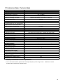
7. Technische Daten / Technical data
Typ
TSM 32 HD
Artikel-Nr. / Art. No.
5903550
Eingänge / Inputs
4 SAT (QUATTRO / QUAD / WIDEBAND)
Frequenzbereich / Frequency range
290 … 2340 MHz
Eingangspegel / Input level
40 … 95 dBµV
ESD-Schutz / ESD protection
alle Eingänge / all inputs
Schaltspannung @ SAT-Eingang /
Switching voltage @ SAT input
AUS / 13 V / 18 V / 0 kHz / 22 kHz
(wählbar via Software / selectable via software)
Strom @ SAT-Eingang /
Current @ SAT input
500 mA
Ausgang / output
1
Frequenzbereich / Frequency range
290 … 2340 MHz *
Ausgangspegel SAT (pro Transponder)/
Output level SAT (per transponder)
112 dBµV
Ausgangspegel SAT @ IM3 35 dB /
Output level SAT @ IM3 35 dB
132 dBµV
Welligkeit / Flatness
<1 dB
Dämpfungssteller / Level adjustment
20 dB
Entzerrer / Slope adjustment
15 dB
Verstärkung SAT / Gain SAT
<40 dB
Testpunkt / Test point
1 (-30 dB zum Ausgangspegel / -30 dB to the output level)
Transponder
Anzahl der Transponder /
Number of transponders
32 (Konvertierung / convertion)
Bandbreite / Bandwidth
1 … 64 MHz (1 MHz Schritte / 1 MHz steps)
Selektivität / Selectivity
35 dB (@ 1 MHz)
Rückflussdämpfung / Return loss
10 dB
SD-Port
Port
1
Funktion / Function
Laden/Sichern der Konfiguration / load/reload of configuration
Betriebsparameter /
Operating parameters
Betriebstemperatur /
Operating temperature
-5 … 50 °C
Maße (BxHxT) / Dimensions (WxHxD)
181 x 165 x 60 mm
Parameter Steckernetzteil /
Parameters power supply
Spannungsversorgung / Power supply
100-240 V~, 50/60 Hz
Leistungsaufnahme /
Power consumption
25 W
Ausgangsspannung / Output voltage
+12 V ±1 V
Ausgangsstrom / Output current
2,5 A
Schutzart / Protection class
Schutzklasse II / protection class II
* Für Ku-Band Transponder bitte die Ausgangsfrequenz im Bereich von 950 … 2200 MHz wählen, um den
Empfang mit handelsüblichen Tunern zu gewährleisten.
* For Ku-band transponders, please select the output frequency in the range of 950… 2200 MHz to ensure
reception with commercially available tuners.

19
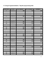
8. Vorlage Programmiertabelle / Template programming table
TRANSPONDER
SAT INPUT
INPUT FRQUENCY
OUTPUT FREQUENCY
BANDWIDTH
1
- 1 - 2 - 3 - 4 -
MHz
MHz
MHz
2
- 1 - 2 - 3 - 4 -
MHz
MHz
MHz
3
- 1 - 2 - 3 - 4 -
MHz
MHz
MHz
4
- 1 - 2 - 3 - 4 -
MHz
MHz
MHz
5
- 1 - 2 - 3 - 4 -
MHz
MHz
MHz
6
- 1 - 2 - 3 - 4 -
MHz
MHz
MHz
7
- 1 - 2 - 3 - 4 -
MHz
MHz
MHz
8
- 1 - 2 - 3 - 4 -
MHz
MHz
MHz
9
- 1 - 2 - 3 - 4 -
MHz
MHz
MHz
10
- 1 - 2 - 3 - 4 -
MHz
MHz
MHz
11
- 1 - 2 - 3 - 4 -
MHz
MHz
MHz
12
- 1 - 2 - 3 - 4 -
MHz
MHz
MHz
13
- 1 - 2 - 3 - 4 -
MHz
MHz
MHz
14
- 1 - 2 - 3 - 4 -
MHz
MHz
MHz
15
- 1 - 2 - 3 - 4 -
MHz
MHz
MHz
16
- 1 - 2 - 3 - 4 -
MHz
MHz
MHz
17
- 1 - 2 - 3 - 4 -
MHz
MHz
MHz
18
- 1 - 2 - 3 - 4 -
MHz
MHz
MHz
19
- 1 - 2 - 3 - 4 -
MHz
MHz
MHz
20
- 1 - 2 - 3 - 4 -
MHz
MHz
MHz
21
- 1 - 2 - 3 - 4 -
MHz
MHz
MHz
22
- 1 - 2 - 3 - 4 -
MHz
MHz
MHz
23
- 1 - 2 - 3 - 4 -
MHz
MHz
MHz
24
- 1 - 2 - 3 - 4 -
MHz
MHz
MHz
25
- 1 - 2 - 3 - 4 -
MHz
MHz
MHz
26
- 1 - 2 - 3 - 4 -
MHz
MHz
MHz
27
- 1 - 2 - 3 - 4 -
MHz
MHz
MHz
28
- 1 - 2 - 3 - 4 -
MHz
MHz
MHz
29
- 1 - 2 - 3 - 4 -
MHz
MHz
MHz
30
- 1 - 2 - 3 - 4 -
MHz
MHz
MHz
31
- 1 - 2 - 3 - 4 -
MHz
MHz
MHz
32
- 1 - 2 - 3 - 4 -
MHz
MHz
MHz

20
Polytron-Vertrieb GmbH
Postfach 10 02 33
75313 Bad Wildbad
Zentrale/Bestellannahme
H.Q. Order department + 49 (0) 70 81 / 1702 - 0
Technische Hotline
Technical hotline + 49 (0) 70 81 / 1702 - 0
Telefax + 49 (0) 70 81 / 1702 - 50
Internet http://www.polytron.de
Email [email protected]
Technische Änderungen vorbehalten
Subject to change without prior notice
Copyright © Polytron-Vertrieb GmbH
-
 1
1
-
 2
2
-
 3
3
-
 4
4
-
 5
5
-
 6
6
-
 7
7
-
 8
8
-
 9
9
-
 10
10
-
 11
11
-
 12
12
-
 13
13
-
 14
14
-
 15
15
-
 16
16
-
 17
17
-
 18
18
-
 19
19
-
 20
20


POLYTRON TSM 32 HD Bedienungsanleitung
- Typ
- Bedienungsanleitung
- Dieses Handbuch eignet sich auch für
in anderen Sprachen
Verwandte Artikel
-
POLYTRON FSA 2-8 A Active SAT Splitter 2x 1 in 8 Bedienungsanleitung
-
-
-
-
-
-
-
-
-
Andere Dokumente
-
Kathrein EXD 2532 Benutzerhandbuch
-
-
Triax TdSCR 508 Benutzerhandbuch
-
Delta Electronics MSW 51 Benutzerhandbuch
-
Axing SKT 40-20M Operation Instructions Manual
-
-
GSS SOQ 100 Brief Assembly Instruction
-
Weishaupt WHI circu 15-3-… #2 Bedienungsanleitung