
1 Wichtige informationen
• Montage, Installation und Service sind von autori-
sierten Elektrofachkräften, die für den Aufbau von
Glasfasernetzen ausgebildet sind, durchzuführen.
• Betriebsspannung der Anlage vor Beginn von Mon-
tage- oder Servicearbeiten abschalten.
•
Führen Sie Installations- und Servicearbeiten nicht
bei Gewittern durch.
• Erden sie das Gerät über die Potentialausgleichs-
schiene (Schrauben ).
• Stellen Sie eine ausreichende Belüftung des Gerä-
tes sicher.
• Vermeiden Sie Kurzschlüsse!
•
Die Normen EN/DIN EN 50083 bzw. IEC/EN/
DIN EN 60728, IEC/EN/DIN EN 61319-1, IEC/EN/
DIN EN 60065 und IEC/EN/DIN EN 60825-1 müs-
sen beachtet werden.
•
Beachten Sie die relevanten Normen, Vorschriften
und Richtlinien zur Installation und zum Betrieb von
Antennenanlagen.
•
Schäden durch fehlerhaften Anschluss und/oder
unsachgemäße Handhabung sind von jeglicher Haf-
tung ausgeschlossen.
Achtung Laser-Klasse 1M
Laserlicht kann zu dauerhaften Augenschäden füh-
ren. Nehmen Sie die Anlage erst wieder in Betrieb,
wenn alle Glasfaserverbindungen sachgerecht ange-
steckt sind und alle unbenutzten optischen Anschlüs-
se mit den Schutzkappen verschlossen sind. Blicken
Sie niemals in offene optische Stecker oder Buchsen
sowie offene optische Fasern, wenn Sie nicht absolut
ausschließen können, dass diese mit Laserlicht belegt
sind.
1 important information
• Assembly, installation and servicing should be car-
ried out by authorised electricians, who are skilled
in constructing optical fibre networks.
• Switch off the operating voltage of the system be-
fore beginning with assembly or service work.
• Do not perform installation and service work during
thunderstorms.
• Earth the unit via the equipotential bonding con-
nector (screws ).
• Make sure the device is adequately ventilated.
• Avoid short circuits!
• The standards EN/DIN EN 50083 resp. IEC/EN/
DIN EN 60728
, IEC/EN/DIN EN 61319-1, IEC/
EN/DIN EN 60065
and
IEC/EN/DIN EN 60825-1
must be observed.
• Observe the relevant standards, regulations and
guidelines on the installation and operation of an-
tenna systems.
• No liability is accepted for damage caused by faulty
connections or inappropriate handling of the device.
Attention - Laser Class 1M
Laser light can cause permanent eye damage.
Only restart the plant, if all used optical fiber con-
nections have been correctly connected and all un-
used optical connections have been closed with a
protective cap. Never look into open optical plugs
or sockets, as well as open optical fibers, unless
you are absolutely sure that these have not been
allocated with laser light.
Kurz-Montageanleitung
Brief Assembly Instruction
Deutsch
English
Optical Equipment
Optical to RF Converter (Quattro)
SOQ 100

- 2 - SOQ 100
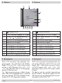
2 Überblick
67890
3
5
4
21
1
Erdungsanschluss
2
FC/PC Optischer Eingang (-15…0 dBm)
3
Anschluss für Versorgungsspannung
10…20 V ; Cinch-Buchse
4
Status-LED für Versorgungsspannung
5
Status-LED für HF-Signal
6
SAT-Ausgang VL (vertikal low)
7
SAT-Ausgang HL (horizontal low)
8
SAT-Ausgang VH (vertikal high)
9
SAT-Ausgang HH (horizontal high)
0
Terrestrischer Ausgang (FM/DAB/DVB-T)
3 beschreibung
SOQ 100 konvertiert die optischen Aus-
gangssignale des LNB GLO 100 (Wellen-
länge 1310 nm, 950…5450 MHz) zurück
auf die 4 SAT-ZF-Bänder (H/H - H/L - V/H
- V/L) und gibt diese über 4 SAT-Ausgangs-
buchsen (F-Buchsen) aus.
Die Spannungsversorgung erfolgt fernge-
speist über die Ausgangsbuchsen. Optional
kann das Netzteil SDP 900 (Zubehör) direkt
an den SOQ 100 angesteckt werden.
2 overvieW
1
Ground connection
2
Optical input FC/PC
(-15…0 dBm)
3
Power supply connector 10…20 V ;
cinch socket
4
Status LED for Power Supply
5
Status LED for RF signal
6
SAT output VL (vertical low)
7
SAT output HL (horizontal low)
8
SAT output VH (vertical high)
9
SAT output HH (horizontal high)
0
Terrestrial output (FM/DAB/DTT)
3 Description
SOQ 100 reconverts the optical output sig-
nals of the LNB GLO 100 (1310 nm wave
length,
950…5450 MHz) into the
4 univer-
sal SAT-IF bands
(H/H - H/L - V/H - V/L)
and outputs them via four SAT output sockets
(F-Type)
.
The device can be remotely powered via
the SAT outputs. The power supply unit SDP
900 (accessory) can alternately be connect-
ed directly to the SOQ 100.

- 3 - SOQ 100
4 installation
• Montieren Sie das Gerät auf schwer
entflammbarem Untergrund (Mauer),
in staubfreier, trockener Umgebung,
geschützt gegen Feuchtigkeit, Dämp-
fe, Spritzwasser und Nässe, an einem,
gegen direkte Sonneneinstrahlung ge-
schützten Ort und nicht in unmittelbarer
Nähe von Wärmequellen.
• Verbinden Sie das Gerät über den Er-
dungsanschluss
1
mit dem Potential-
ausgleich des Systems.
Glasfaser-Verbindung (Eingang)
Beachten Sie die Laser-Hinweise auf der
Titelseite.
•
Das Glasfaserkabel muss mit FC/PC-Ste-
ckern versehen werden. Andere Stecker
können die FC/PC-Buchsen des Geräts be-
schädigen. Fertige Kabel sind in verschie-
denen Längen von 1…200 m erhältlich.
• Glasfaser-Stecker und -Buchsen müssen
frei von Staub sein und sollten mit Isopro-
pylalkohol gereinigt werden.
• Prüfen Sie, dass die optische Leistung
des Eingangssignal im Bereich von
-15 dBm…0 dBm liegt. Führen Sie bei
Bedarf Anpassungen durch.
• Stecken Sie den FC/PC-Stecker des
Glasfaserkabels in die FC/PC-Buchse
2
des Geräts und verschrauben Sie die
Verbindung.
SAT-Kabel-Verbindungen (Ausgänge)
•
Verbinden Sie die SAT-Ausgänge (6 H/H -
7 H/L - 8 V/H - 9 V/L) mit den entspre-
chenden Eingängen des nachgeschalteten
Geräts ihrer Anlage (z.B. Multischalter).
Spannungsversorgung
Das Gerät ist für Fernspeisung über die SAT-
Ausgänge geeignet (10…20 V ).
Alternativ kann das Netzteil SDP 900 (Zu-
behör) direkt an den SOQ 100 angesteckt
werden. Liegt eine Versorgungsspannung
an, leuchtet die Status-LED
4
.
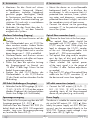
4 installation
• Mount the device
on a non-flammable
background (wall),
in a dust-free, dry
environment, in such a manner that it is
protected from moisture, fumes, splash-
ing water and dampness, somewhere
protected from direct sunlight, not within
the immediate vicinity of heat sources.
• Connect the device via the grounding
connector
1
to the potential equalisa-
tion of the system.
Optical fibre connection (input)
Observe the laser hints at the front page.
• The optical fibre cable should be
equipped with FC/PC plugs. Only the
FC/PC may be used. Other plugs can
lead to damage the FC/PC- coupler
of the unit. Preconfigured cables with
length of 1…200 m are available.
• The optical fibre plug and/or couplers
must be free of dust and should be
cleaned with Isopropyl alcohol.
• Check whether the optical power
of the input signal is in the range of
-15 dBm…0 dBm. Perform adjustments
as needed.
• Plug the FC/PC plug of the optical fibre
cable into the FC/PC connector
2
of
the device and screw them together.
SAT cable connections (outputs)
•
Connect the SAT outputs (6 H/H - 7
H/L - 8 V/H - 9 V/L) to the corre-
sponding inputs of the downstreamed
device of your plant (e.g. multiswitch).
Power Supply
The device is suitable for remote power sup-
ply via the SAT outputs (10…20 V ). Alter-
nately the power supply unit SDP 900 (ac-
cessory) can be connected directly to the
SOQ 100. If power supply voltage is sup-
plied, status LED
4
lights up.

Terrestrial output
As the LNB GLO 100 does not provide ter-
restrial signals, output
0
is not used.
Appropriate signal sources are available on
request.
Terrestrischer Ausgang
Da das LNB GLO 100 als Signalquelle kei-
ne terrestrischen Signale liefert, ist der Aus-
gang
0
ohne Funktion. Geeignete Signal-
quellen erhalten Sie auf Anfrage.
Service:
Phone: +49 (0) 911 / 703 2221 • Fax: +49 (0) 911 / 703 2326 • Email: ser[email protected]
Grundig SAT Systems GmbH • Beuthener Straße 43 • D-90471 Nürnberg
Änderungen vorbehalten. Technische Angaben ohne Gewähr. © by GSS GmbH 25102012
Alterations reserved. Technical data E. & O.E.
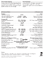
6 technische Daten 6 technical Data
Eingang Input
Optischer Eingang ..................................FC/PC .........................................Optical input
Optische Eingangsleistung ............-15 dBm … 0 dBm ..................... Optical input power
Optische Wellenlänge ................1100 nm … 1650 nm ....................Optical wavelength
Ausgang SAT SAT Output
Ausgangsfrequenzbereich .............. 950…2150 MHz ...........SAT Output frequency range
Ebenen ......................................... VL, HL, VH, HH .......................................Polarities
Rückflussdämpfung .............................. ≥ 10 dB ..........................................Return loss
Ausgangsimpedanz ................................75 Ω ................................ Output impedance
Nominaler Ausgangspegel ...................75 dBµV ........................... Nominal output level
(bei 30 Transpondern) (for 30 transponders)
Ausgang DVB-T, DAB, FM DTT, DAB, FM Output
DVB-T Ausgangsfrequenzbereich ...... 470…862 MHz ............DTT Output frequency range
DAB-Ausgangsfrequenzbereich ........ 174…240 MHz ...........DAB Output frequency range
FM-Ausgangsfrequenzbereich ...........88…108 MHz ..............FM Output frequency range
Rückflussdämpfung .............................. ≥ 10 dB ..........................................Return loss
Ausgangsimpedanz ................................75 Ω ................................ Output impedance
Nominaler Ausgangspegel DVB-T ..........68 dBµV ..................... Nominal output level DTT
(bei 6 Transpondern) (for 6 transponders)
Elektrische und allgemeine Daten Electrical and general data
Betriebsspannung LNB ................10 V … 20 V
...............LNB operating voltage
Stromaufnahme (bei 10V) ...................... 210 mA .................Current consumption (at 10V)
Fernspeisung .....................über SAT-Ausgänge/via SAT outputs ........ Remote power supply
Betriesspannungsanschluss .........Cinch-Buchse/cinch socket ..................DC input connector
Betriebstemperatur ...............................0…+40 °C ....................... Operating temperature
Anschlüsse Connectors
Ausgänge ...............................5 (F-Buchse/female F-Type) ...................................Outputs
Stromversorgung (über SDP 900)
... 1 Cinch-Buchse/socket .........Power supply (via SDP 900)
-
 1
1
-
 2
2
-
 3
3
-
 4
4


in anderen Sprachen
- English: GSS SOQ 100
Andere Dokumente
-
Kathrein OEC 44 mini Benutzerhandbuch
-
-
Axing SFK99902 Benutzerhandbuch
-
ASTRO 408 130 Benutzerhandbuch
-
Triax QUAD TVC 05 Installationsanleitung
-
POLYTRON OPM-CON Bedienungsanleitung
-
-
-
-