Seite wird geladen ...

DI51 463 20
Montageanleitung
Installation manual
G 463
Integral Doppelscheinwerfereinsätze LHD
Integral four headlamp inserts LHD
Modell 2003 ab 06.2002
from year 06.2002
Stand 16.12.2003
dated from 2003-12-16
Technische Änderungen vorbehalten
specifications are subject to change
Seite 1/5
side 1/5
Artikelnummer / part number:
Artikelbezeichnung / designation:
Modell / model:
1
(10)
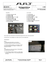
ACHTUNG, wichtiger Hinweis:
Die Scheinwerfer sind spritzwassergeschützt, aber nicht wasserdicht!
ATTENTION, important note:
The headlights are splash-proof, but not waterproof!
Stückliste:
2 x Frontblende links (1a) und rechts (1b)
2 x Nebelscheinwerfer Halogen links (2a) und rechts (2b)
2 x Fernscheinwerfer Xenon links (3a) und rechts (3b)
1 x Kabelbaum (4)
6 x Kabelbinder (5)
8 x Unterlegscheiben 6,4x20mm (6)
8 x Muttern 6mm (7)
2 x Flachsteckerhülsen (8)
4 x Flachstecker 6,3mm (9)
2 x Steuergerät (10)
1 x Bohrschablone (siehe Anhang)
List of parts:
2 x front mask left (1a) and right (1b)
2 x fog lamps halogen left (2a) and right (2b)
2 x high beams Xenon left (3a) and right (3b)
1 x wiring harness (4)
6 x cable strap (5)
8 x wearing parts 6,4x20mm (6)
8 x nuts 6mm (7)
2 x flat pin housing (8)
4 x flat pin 6,3mm (9)
2 x control unit (10)
1 x drilling template (see appendix)
Links / left
DI51 463 21
Rechts / right
DI51 463 22
(1a)
(2a)
(2b)
(3a)
(3b)
(4)
(5)
(6)
(7)
(8)
(9)
(1b)

DI51 463 20
Montageanleitung
Installation manual
G 463
Integral Doppelscheinwerfereinsätze LHD
Integral four headlamp inserts LHD
Modell 2003 ab 06.2002
from year 06.2002
Stand 16.12.2003
dated from 2003-12-16
Technische Änderungen vorbehalten
specifications are subject to change
Seite 2/5
side 2/5
Artikelnummer / part number:
Artikelbezeichnung / designation:
Modell / model:
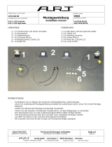
Bild 2:
3. Schnittkanten anzeichnen und mit
Druckluftsäge ausschneiden.
fig.2:
3. Draw the cutting edge and then cut out with
compressed air saw.
Bild 3:
4. Anhand der Bohrschablone die benötigten
Löcher anzeichnen und mittels Körner anreißen.
Führungen für die Stehbolzen Ø 6,5mm bohren.
fig.3:
4. Mark on basis of the drilling template the necessary
holes and scribe them by means of grains.
Bore with a 6,5mm strong metal drill the guidance
for the staybolts
Bild 2
Bild 3
Arbeitsablauf:
Bild 1:
1. Stoßstange demontieren und säubern,
vorhandene Nebelscheinwerfer demontieren.
2. Schnitt und Bohrschablone zuschneiden.
- Kante A an Stossstangenecke anlegen
- Schablone mit Klebeband fixieren
fig.1:
1. Dismantle and clean the bumper,
deinstallation of existing fog lamp system.
2. Cut the drilling template and the cut.
- apply edge A to the bumper corner
- fix the drilling template with tape.
Bild 1
A

DI51 463 20
Montageanleitung
Installation manual
G 463
Integral Doppelscheinwerfereinsätze LHD
Integral four headlamp inserts LHD
Modell 2003 ab 06.2002
from year 06.2002
Stand 16.12.2003
dated from 2003-12-16
Technische Änderungen vorbehalten
specifications are subject to change
Seite 3/5
side 3/5
Artikelnummer / part number:
Artikelbezeichnung / designation:
Modell / model:
Bild 6:
7. Die Doppelscheinwerferblende von außen
aufsetzen, gegebenenfalls die Stehbolzen
vorsichtig ausrichten. Blende mit den
Beilagscheiben ( 4) und Muttern (5) fixieren.
fig. 6:
7. Attach the double headlight screen from the
outside (align the staybolts carefully) and fix
them with the attached 6mm wearing parts (4)
and with the nuts (5)
Bild 5
Steg B
Bild 5:
6. Mit der Druckluftsäge die angezeichneten
Aussparungen aussägen.
ACHTUNG! Steg B muss erhalten bleiben.
Auschnittkanten gegen Rost versiegeln.
fig. 5:
6. Saw-out the drawn recesses with a compressed air
saw.
NOTE! Bar B must also remain.
Seal the cutting edges against rust and possibly
in-grow the edges.
Bild 6
Stoßstangenecke
Bumper corner
Bild 4:
5. An der hinteren Seite der Stoßstange die
Aussparungen für die Doppelscheinwerfer
anzeichnen. (Auf ausreichend Platz achten)
fig. 4:
5. Mark the recesses for the double headlights at the
back of the bumper. (pay attention to sufficiently
place)
Bild 4

DI51 463 20
Montageanleitung
Installation manual
G 463
Integral Doppelscheinwerfereinsätze LHD
Integral four headlamp inserts LHD
Modell 2003 ab 06.2002
from year 06.2002
Stand 16.12.2003
dated from 2003-12-16
Technische Änderungen vorbehalten
specifications are subject to change
Seite 4/5
side 4/5
Artikelnummer / part number:
Artikelbezeichnung / designation:
Modell / model:
Bild 8:
10. Bringen Sie die beiden Steuergeräte für die Xenon
Fernscheinwerfer an geeigneter Stelle (evtl. Stossstangen-
innenseite) an.
Fig. 8:
10. Fix the two controllers for xenon high beain on a suitable
place.
Bild 8
Bild 7
Nebelscheinwerfer
Fog beam
Fernscheinwerfer
High beam
C
A
B
Bild 7:
8. Kunststoffgewindeaufsätze der Stellschrauben C
anwärmen und in Frontblende einsetzen.
Beide Doppelscheinwerfer einsetzen.
Fernscheinwerfer Fahrzeugaußenseite A ,
Nebelscheinwerfer Fahrzeuginnenseite B.
Siehe Bild 7.
fig. 7:
8. Afterwards attach the two headlights. Install the
high beams on the vehicle exterior side A,
install the fog lamps on the vehicle interior side
B. Warm up the plastic-clips C for the headlight
adjusting screws and set it in.
See figure 7.
9. Verkabelung der Scheinwerferanlage:
- Nebelscheinwerfer innen liegend.
Flachstecker und Flachsteckhülsen auf Serienkabel setzen und Verbindung herstellen.
- Fernscheinwerfer außen liegend.
Mit Leitungssatz gemäß Anschlussplan (unten) verdrahten.
9. Wiring of electrical connection diagram:
- Fog lamps on the interior side.
Attach the flat pin and the flat pin housing with the serial wireness and connect it.
- High beam on the exterior side.
Connect it according the connecting diagram.

DI51 463 20
Montageanleitung
Installation manual
G 463
Integral Doppelscheinwerfereinsätze LHD
Integral four headlamp inserts LHD
Modell 2003 ab 06.2002
from year 06.2002
Stand 16.12.2003
dated from 2003-12-16
Technische Änderungen vorbehalten
specifications are subject to change
Seite 5/5
side 5/5
Artikelnummer / part number:
Artikelbezeichnung / designation:
Modell / model:
tuning gmbh - Am Keuper 3 - 90475 Nürnberg - Germany
Telephone +49(0)9128 -92500 Fax +49(0)9128 -920502 info@ART-tuning.com www.ART-tuning.com
Anschlussplan für Fernscheinwerfer:
Connecting diagram for high beam system:
1/5