
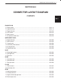
TABLE OF CONTENTS
CONNECTOR LAYOUT DIAGRAM
INSTALLATION POSITIONS
OF SINGLE UNIT PARTS
GROUND POINT
POWER SUPPLY DIAGRAM
SYSTEM CIRCUIT DIAGRAM
LIST OF CONNECTORS
SECTION
HOW TO USE THIS MANUAL
8A-1
8A-3
8A-4
8A-5
8A-6
8A-7
8A-8
FOREWORD
OVERSEAS SERVICE DEPARTMENT
© COPYRIGHT SUZUKI MOTOR CORPORATION 2000
This manual has been prepared to help inspection
and service works involving electric wiring of the fol-
lowing model be done efficiently.
Applicable model : SQ416/420/625
(For VIN of applicable vehicles, refer to Applicability
in page 8A-1-2 of this manual.)
In order to make a good use of this manual, it is im-
portant to have a full understanding of its first section
"HOW TO USE THIS MANUAL".
All the data and information contained in this manual
are based on the vehicle of certain specifications.
Therefore, please note that the actual vehicle being
serviced may vary somewhat because of differences
in specifications or statutory regulations.
All information, illustrations and specifications con-
tained in this literature are based on the latest prod-
uct information available at the time of publication
approval. And used as the main subject of descrip-
tion is the vehicle of standard specifications among
others. Therefore, note that illustrations may differ
from the vehicle being actually serviced. SUZUKI MO-
TOR CORPORATION reserves the right to make
changes at any time without notice.
For inspection and service works of electrical parts,
following reference materials are also available for
your help.
RELATED SERVICE MANUAL
• SQ416/420/625 Service Manual
...................................................................................................................
99500-65D10-01E
99500-65D00-01F
99500-65D00-01G
99500-65D00-01S
• SQ416/420/625 Supplementary Service Manual
...............................................
.........................................99501-65D10-01F
99501-65D20-01F
99501-65D10-01G
99501-65D20-01G
99501-65D10-01S
99501-65D20-01S
• SQ420WD Service manual
...........................................................................................................................
99500-68D00-01E
99500-68D00-01F
99500-68D00-01G
99500-68D00-01S

INHALTSVERZEICHNIS
STECKER-LAYOUT-DIAGRAMM
EINBAUPOSITIONEN VON
EINZELEINHEIT-TEILEN
MASSEPUNKT
STROMVERSORGUNGSDIAGRAMM
SYSTEMSCHALTDIAGRAMM
LISTE DER STECKER
ABSCHNITT
VERWENDUNG DIESER ANLEITUNG
8A-1
8A-3
8A-4
8A-5
8A-6
8A-7
8A-8
VORWORT
AUSLANDSABTEILUNG
© COPYRIGHT SUZUKI MOTOR CORPORATION 2000
Dieses Handbuch wurde als Hilfe für Inspektions- und
Wartungsarbeiten an der Fahrzeugelektrik des
folgenden Modells zusammengestellt.
Betreffendes Modell :SQ416/420/625
(Hinsichtlich VIN des betreffenden Modells, siehe den
Abschnitt ANWENDBARKEIT auf Seite 8A-1-18
dieser Anleitung.)
Um den größtmöglichen Nutzen aus diesem
Handbuch zu ziehen, ist es wichtig, den ersten
Abschnitt "VERWENDUNG DIESER ANLEITUNG"
gründlich zu verstehen.
Sämtliche in diesem Handbuch enthaltenen
Spezifikationen und Informationen basieren auf den
technischen Daten eines bestimmten Modells. Es ist
deshalb zu beachten, daß die technischen Daten und
vorschriftsmäßige Ausstattung des zur Inspektion
gebrachten Fahrzeugs sich eventuell leicht von den
hier angegebenen Spezifikationen unterscheiden.
Alle in diesem Handbuch gegebenen informationen,
Abbildungen und Spezifikationen basieren auf den
neuesten Daten, wie sie zum Zeitpunkt der
Drucklegung zur Verfügung standen. Die Angaben
beziehen sich größtenteils auf Fahrzeuge mit
Standardspezifikationen. Sie weichen daher zuweilen
von den tatsächlichen Gegebenheiten des zu
wartenden Fahrzeugs ab. Das Recht zu
Veränderungen, auch unangemeldet, behalten wir
uns vor. Die SUZUKI MOTOR CORPORATION
behält sich das Recht auf Änderungen jederzeit und
ohne vorherige Ankündigung vor.
Für Inspektions- und Wartungsarbeiten an
elektrischen Bauteilen ist als zusätzliche Hilfe auch
das folgende Bezugsmaterial erhältlich.
MODELLBEZOGENE WARTUNGSANLEITUNGEN
• SQ416/420/625 Wartungsanleidung
............................................................................................................
99500-65D10-01E
99500-65D00-01F
99500-65D00-01G
99500-65D00-01S
• SQ416/420/625 Ergänzende Wartungsanleitung
........................................................................................
99501-65D10-01F
99501-65D20-01F
99501-65D10-01G
99501-65D20-01G
99501-65D10-01S
99501-65D20-01S
• SQ420WD Wartungsanleidung
....................................................................................................................
99500-68D00-01E
99500-68D00-01F
99500-68D00-01G
99500-68D00-01S

TABLES DES MATIÈRES
SCHÉMA DE DISPOSITION
DES BLOCS RACCORD DE CÂBLAGE
POSITIONS D'INSTALLATION
DES PIÈCES INDIVIDUELLES
POINTS MASSE
SCHÉMA DU CIRCUIT D´ALIMENTATION
SCHÉMA DES SYSTÈMES ÉLECTRIQUES
LISTE DES BLOCS RACCORD
DE CÂBLAGE
SECTION
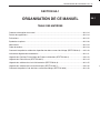
ORGANISATION DE CE MANUEL
8A-1
8A-3
8A-4
8A-5
8A-6
8A-7
8A-8
AVANT-PROPOS
SERVICE APRÈS-VENTE ÉTRANGER
© COPYRIGHT SUZUKI MOTOR CORPORATION 2000
Le but de ce manuel est de permettre d'effectuer des
travaux d'entretien et de réparation efficaces, en
particulier sur les circuits électriques du modèle
suivant.
Modèle couvert :SQ416/420/625
(Voir DÉTAILS DES APPLICATIONS à la page 8A-
1-34 de ce manuel pour les numéros d’identification
des véhicules concernés.)
Pour tirer le meilleur parti de ce manuel, il est indis-
pensable d'avoir pris connaissance de la première
partie "ORGANISATION DE CE MANUEL".
Toutes les données et informations contenues dans
ce manuel se rapportent à un véhicule précis ayant
certaines spécifications. Le véhicule qui sera réparé
pourra être un peu différent du fait de ses spécification
ou de la réglementation officielle.
Toutes les informations, illustrations et spécifications
contenues dans ces pages sont basées sur les infor-
mations produit les plus récentes à la mise sous
presse. Les descriptions principales concernent les
véhicules aux spécifications standards. Veuillez donc
noter pue les illustrations peuvent présenter des
différences par rapport aux véhicules en question.
SUZUKI MOTOR CORPORATION se réserve le droit
de procéder à des modifications sans préavis.
Pour les travaux d'entretien et de réparation des
pièces électriques, les références suivantes sont
également disponibles.
MANUEL D'ENTRETIEN APPROPRIE
• Manuel d'entretien des SQ416/420/625
.......................................................................................................
99500-65D10-01E
99500-65D00-01F
99500-65D00-01G
99500-65D00-01S
• Manuel d'entretien complémentaire des SQ416/420/625
.........................................................................
99501-65D10-01F
99501-65D20-01F
99501-65D10-01G
99501-65D20-01G
99501-65D10-01S
99501-65D20-01S
• Manuel d'entretien des SQ420WD
.................................................................................................................
99500-68D00-01E
99500-68D00-01F
99500-68D00-01G
99500-68D00-01S

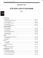
ÍNDICE
DIAGRAMA DE DISPOSICIÓN
DE CONECTORES
POSICIONES DE INSTALACIÓN DE
PARTES DE UNIDAD SENCILLA
PUNTOS DE MASA
DIAGRAMA DE LA ALIMENTACIÓN
ELÉCTRICA
DIAGRAMA DEL CIRCUITO DEL
SISTEMA
LISTA DE CONECTORES
SECCIÓN
MODO DE EMPLEO DE ESTE
MANUAL
8A-1
8A-3
8A-4
8A-5
8A-6
8A-7
8A-8
INTRODUCCIÓN
DEPARTAMENTO DE SERVICIO DE ULTRAMAR
© COPYRIGHT SUZUKI MOTOR CORPORATION 2000
Este manual ha sido preparado para ayudar a
efectuar de forma eficaz los trabajos de inspecciones
y servicio relacionados con el sistema el eléctrico
del modelo siguiente.
Modelo aplicable :SQ416/420/625
(Para ver el número VIN de los vehículos aplicables,
consulte la sección de APLICACIÓN en la página
8A-1-50 de este manual.)
Con el fin de emplear correctamente este manual,
es importante comprender bien la primera sección
de "MODO DE EMPLEO DE ESTE MANUAL".
Todos los datos e información contenidos en este
manual se basan en el vehículo con ciertas
especificaciones. Por lo tanto, habrá que tener
presente que el vehículo en el que realmente se está
realizando el servicio puede variar en cierto grado
debido a las diferencias de las especificaciones o de
las regulaciones establecidas por la ley.
Toda la información, figuras y especificationes de este
manual se basan sobre la última información
aprobada del producto, disponible al momento de su
publicación, Y el principal modelo utilizado para la
descripción a lo largo de este manual es el modelo
con especificaciones básicas. Por lo tanto, las figuras
pueden ser diferentes con respecto al vehículo que
vino al servicio, SUZUKI MOTOR CORPORATION
se reserva el derecho a hacer cambios en cualquier
momento sin previo aviso.
Para la inspección y servicio de las partes eléctricas,
es aconsejable consultar también los siguientes
materiales de referencia.
MANUAL DE SERVICIO RELACIONADO
• Manual de servicio SQ416/420/625
..............................................................................................................
99500-65D10-01E
99500-65D00-01F
99500-65D00-01G
99500-65D00-01S
• Manual de servicio suplementario SQ416/420/625
...................................................................................
99501-65D10-01F
99501-65D20-01F
99501-65D10-01G
99501-65D20-01G
99501-65D10-01S
99501-65D20-01S
• Manual de servicio SQ420WD
......................................................................................................................
99500-68D00-01E
99500-68D00-01F
99500-68D00-01G
99500-68D00-01S

8A-6-1HOW TO USE THIS MANUAL 8A-1-1
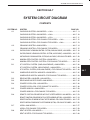
SECTION 8A-1
HOW TO USE THIS MANUAL
CONTENTS
· Manual Contents and Description ...................................................................................................... 8A-1-2
· Applicability ........................................................................................................................................ 8A-1-2
· Cautions in Servicing ......................................................................................................................... 8A-1-3
· Symbols and Marks............................................................................................................................ 8A-1-6
· Abbreviations...................................................................................................................................... 8A-1-7
· Wire Color Symbols............................................................................................................................ 8A-1-7
· How to Read Connector Layout Diagram (SECTION 8A-3)............................................................... 8A-1-8
· Indication of Connectors and How to Read them............................................................................... 8A-1-9
· How to Read Installation Positions of Single Unit Parts (SECTION 8A-4) ....................................... 8A-1-11
· How to Read Ground Point (SECTION 8A-5) .................................................................................. 8A-1-12
· How to Read Power Supply Diagram (SECTION 8A-6) ................................................................... 8A-1-13
· How to Read System Circuit Diagram (SECTION 8A-7).................................................................. 8A-1-14
· How to Read List of Connectors (SECTION 8A-8) .......................................................................... 8A-1-16
8A-1

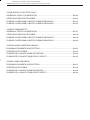
8A-1-2 HOW TO USE THIS MANUAL
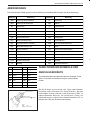
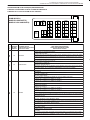
MANUAL CONTENTS AND DESCRIPTION
This manual consists of diagrams showing the harness routing, connector layout, installation positions of single
unit parts (fuse, relay, control unit), ground points, power circuit, system circuit and list of connectors.
VIN:Vehicle Identification Number
SECTION
Power Supply Diagram
System Circuit
Diagram
Ground Point
8A-3
8A-4
8A-6
8A-7
8A-8
8A-5
DESCRIPTION
Arrangement of connectors used in this vehicle is shown in relation with the wiring
harness by using symbols in illustration.
Electric flow passage from the positive terminal of the battery to the main fuse and
each fuse in the fuse box are shown and names of main systems that apply a load
to each fuse are indicated.
Individual circuit from the fuse to the ground of each system is shown.
The circuit diagram is designed so as to show the electric flow from the top to the
bottom in it.
Shapes of connectors used in this vehicle and arrangements of their pins are shown.
Positions where each fuse, relay and control unit are installed in this vehicle are
shown.
Points on the body where grounding is made are shown.
Connector Layout
Diagram
Installation Positions of
Single Unit Parts
List of Connectors
APPLICABILITY
This manual is applicable to the vehicles listed below.
NOTE:
Bear in mind that description in the text may vary from the actual vehicle depending on specifications.
2WD ................................ JS3TE62V X4100001~
4WD ................................ JS3TD62V X4100001~

8A-6-3HOW TO USE THIS MANUAL 8A-1-3
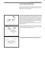
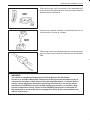
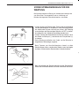
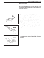
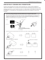
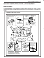
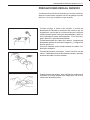
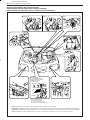
CAUTIONS IN SERVICING
When performing works related to electric systems, observe fol-
lowing cautions for the purpose of protection of electrical parts and
prevention of a fire from occurrence.
· When removing the battery from the vehicle or disconnecting
the cable from the battery terminals for inspection or service
works on the electric systems, always confirm first that the
ignition switch and all the other switches have been turned
OFF. Otherwise, the semi-conductor part may be damaged.
· When disconnecting cables from the battery, be sure to dis-
connect the one from the negative (
-
) terminal first and then
the other from the positive (+) terminal.
· Reverse the above order when connecting the cables to the
battery terminals.
· When disconnecting connectors, never pull the wiring har-
nesses. Unlock the connector lock first and then pull them
apart by holding connectors themselves.
· When connecting connectors, also hold connectors and put
them together until they lock securely (a click is heard).
NO!

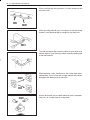
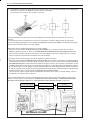
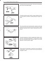
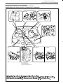
8A-1-4 HOW TO USE THIS MANUAL
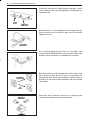
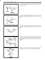
· When installing the wiring harness, fix it with clamps so that
no slack is left.
· When installing vehicle parts, be careful so that the wiring
harness is not interfered with or caught by any other part.
· To avoid damage to the harness, protect its part which may
contact against a part forming a sharp angle by winding tape
or the like around it.
· When replacing a fuse, make sure to use a fuse of the speci-
fied capacity. Use of a fuse with a larger capacity will cause a
damage to the electrical parts and a fire.
· Always be careful not to handle electrical parts (computer,
relay, etc.) in a rough manner or drop them.
OK
NO!
NO!
NO!
OK
NO!

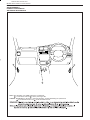
8A-6-5HOW TO USE THIS MANUAL 8A-1-5
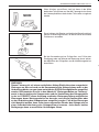
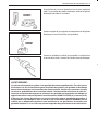
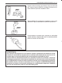
· When performing a work that produces a heat exceeding 80˚C
in the vicinity of the electrical parts, remove the heat sensitive
electrical part(s) beforehand.
· Use care not to expose connectors and electrical parts to wa-
ter which will be a cause of a trouble.
· When using a tester for checking continuity or measuring volt-
age, be sure to insert the tester probe from the wire harness
side.
NO!
NO!
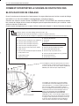
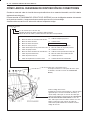
WARNING:
This vehicle is equipped with Supplemental Inflatable Restraint Air Bag System.
Service on or around Air Bag System Components or Wiring must be performed only by an
authorized Suzuki dealer. Please observe all the warnings described in "On Vehicle Service
section", the Air Bag System Component and Wiring Location View in the service manual
mentioned in FOREWORD of this manual before performing service on or around Air Bag
System Components or Wiring. Failure to follow WARNING could result in unintended air
bag deployment or could render the air bag inoperative. Either of these two conditions may
result in severe injury.

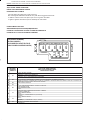
8A-1-6 HOW TO USE THIS MANUAL
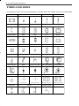
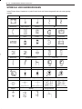
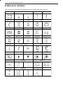
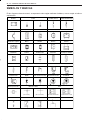
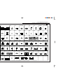
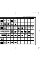
SYMBOLS AND MARKS
In the diagrams of this manual, each equipments are represented by the symbols and marks as shown below.
Battery Ground Normal Fuse Slow blow fuse
Circuit breaker Coil, Solenoid Heater Bulb
Cigarette lighter Motor Pump Horn Speaker
Buzzer Chime Condenser Thermistor Reed switch
Resistance Variable resistance Transistor
Photo transistor Diode
Reference (zener) diode
Light emitting diode Photo diode
Piezoelectric element
Harness Relay
SwitchConnector "O" Type terminal
(Connected)
(Not connected)
Normal open relay
Normal closed relay

8A-6-7HOW TO USE THIS MANUAL 8A-1-7
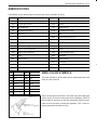
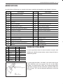
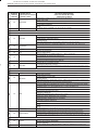
ABBREVIATIONS
Listed below are the abbreviations as used in this manual and their full terms.
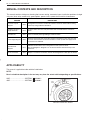
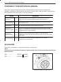
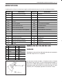
WIRE COLOR SYMBOLS
The initial alphabet (s) of the color name is used to represent each
color as listed at the left.
There are two types of wire color : one-color type and 2-color type
(with a stripe). In case of 2-color type, the first alphabet ("GRN" of
the example in the figure at the left) represents the basic color
(color of wire insulation) and the next alphabet ("YEL" of the ex-
ample) represents the color of stripe.
Abbreviation AbbreviationFull term
2 wheel drive vehicles
4 wheel drive vehicles
Air conditioning
Automatic transmission
Accessory
Crank shaft position
Camshaft position
Data link connector
Daytime running light (If equipped)
Engine coolant temperature
Exhaust gas recirculation
High
Idle air control
Intake air temperature
Transmission control module
Ignition
ILL
IND
J/C
LH (D)
LO
MAP
M/T
P/N
RH (D)
ST
TCC
W/S
P/S
INT
O/D
VSV
Illumination
Indicator
Joint connector
Left hand (drive vehicle)
Low
Manifold absolute pressure
Manual transmission
Power/Normal
Right hand (drive vehicle)
Starter
Torque converter clutch
Weld splice
Power steering
Intermittent
Over drive
Vacuum switching valve
Full term
2WD
4WD
A/C
A/T
ACC
CKP
CMP
DLC
DRL
ECT
EGR
HI
IAC
IAT
TCM
IG
Symbol
BLK
BLU
BRN
GRN
GRY
LT BLU
LT GRN
Wire core
Black
Blue
Brown
Green
Gray
Light Blue
Light Green
Symbol
ORN
RED
WHT
YEL
PNK
PPL
Wire core
Orange
Red
White
Yellow
Pink
Violet
GRN(Base Color)
GRN(Base Color)
YEL (Stripe Color)
Symbol
GRN : Green
GRN/YEL : Green/Yellow
GRN/YEL

8A-1-8 HOW TO USE THIS MANUAL
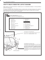
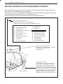
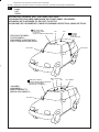
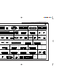
HOW TO READ CONNECTOR LAYOUT DIAGRAM
When necessary to know the location of an electrical part or an intermediate connector, it is easily possible to
retrieve it by this diagram.
First consult “SYSTEM CIRCUIT DIAGRAM” section or connector table at the right hand pages of this section for
the questioned connector code. Second refer to the diagrams of this section and look for the same code.
More information on use of the code is illustrated below.
This indicates the ground point No.
The same No. is used as the ground point. (For the
details, refer to "GROUND POINT" section)
This indicates the connector code.
The connector code in the parentheses ( ) has the same
meaning as the above intermediate connector and at the
same time, it indicates that there is a harness continuity
between pages or illustrations in CONNECTOR LAYOUT
DIAGRAM section. That is, it suggests that the harness
is continued to the other page or illustration and the
continued harness can be identified by the same con-
nector code.
Connector code
}
Harness symbol and corresponding harness name
A : Battery cable K : Room light harness
B : A/C harness K : Spot light wire
C : Engine harness K : Roof wire
D : Injector harness L : Floor harness
E : Main harness M : Rear bumper wire
E : Oil pressure switch wire O : Back door harness
E : Console wire O : License plate wire
G : Instrument panel harness O : High mounted stop light wire
J : Front door wire Q : Air bag harness
J : Rear door wire Q : Pretensioner wire
J : Rear joint wire R : Fuel pump wire
L 0 1
Connector No (serial No : 01)
Harness symbol (Refer to the table below)

8A-6-9HOW TO USE THIS MANUAL 8A-1-9
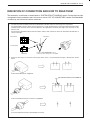
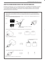
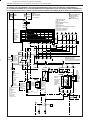
INDICATION OF CONNECTORS AND HOW TO READ THEM
The connectors are indicated as shown below in "SYSTEM CIRCUIT DIAGRAM" section. For the shape and pin
arrangement of each connector used in this manual, refer to "LIST OF CONNECTORS" section. Described below
are how they are indicated and how to read them.
1. · The male terminal and female terminal are identified by a double enclosure and a single one respectively.
· The intermediate connector which connects harnesses is shown by both shapes of the male terminal and the female
terminal but the connector to be connected directly to the equipment is shown by the shape of the connector on the
harness side.
· The connectors described in this manual are always "harness side connectors" which are viewed from the direction as
shown at the right..
2. · There are three types of connectors with respect to the way it is connected and each type is illustrated as shown
below.
· To be inserted directly into equipment
· To be connected with harness connector of equipment
· To connect between harnesses (intermediate connector)
8765
4321
578
1234
6
A40
D18
5
D18
A40
Terminal No.
Terminal No.
Consult "LIST OF CONNECTOR" section
for the pin position refering to this code (D18-5).
Male terminal
Female terminal
This indicates that they are indedntical.
B15 2

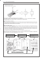
8A-1-10 HOW TO USE THIS MANUAL
3. · Wiring of this vehicle uses joint connectors (J/C) which divide one wire into several different wires or combine several
different wires into one wire.
· The joint connector is illustrated below.
How to Read Connector Codes and Pin Nos. (How to Use Manual) :
It is possible to retrieve the location and shape of each connector from the connector code indicated in "SYSTEM
CIRCUITDIAGRAM" section and the position of each pin from the connector pin No.
To retrieve location of connector :
Open "SYSTEM CIRCUIT DIAGRAM" section to consult the connector code of the questioned connector. Then, refer to
"CONNECTOR LAYOUT DIAGRAM" section and look for the same code as the connector code in question. The place
where the code is found is the location of that connector.
To retrieve shape or pin No.
Open "SYSTEM CIRCUIT DIAGRAM" section to consult the connector code and pin No. of the questioned connector.
Then, refer to "LIST OF CONNECTORS" section as shown at the right in the figure below and look for the desired
connector code under which the shape of that connector is shown. This method is convenient when locating the connec-
tor in question among similar connectors. Also, by using this page, it is possible to find the position of each pin from the
connector pin No. provided in "SYSTEM CIRCUIT DIAGRAM" section.
It is helpful when retrieving pin position in the connector for checking continuity between pins.
To know the location, shape or pin position of the connector, cross-refer "SYSTEM CIRCUIT DIAGRAM", "CONNECTOR
LAYOUT DIAGRAM" and "LIST OF CONNECTOR" section as follows:
CONNECTOR LAYOUT DIAGRAM
Retrieve the connector location
SYSTEM CIRCUIT DIAGRAM
Consult the connector code and
pin No.
LIST OF CONNECTORS
Retrieve shape or pin position
of the connector.
CROSS-REFERENCE

8A-6-11HOW TO USE THIS MANUAL 8A-1-11
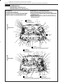
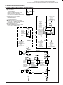
<1.6L>
<2.0L>
<2.5L>
*This illustration is 2.0L model
*Diese Abbildung zeigt das 2,0-Liter-Modell
*Cette illustration représente le modèle 2,0 litres
*Esta ilustración es del modelo 2.0L
BLK/WHT
BLK
NOISE SUPPRESSOR (C03)
STÖRUNGSUNTERDRÜCKER
CONDENSATEUR ANTIPARASITE
SUPRESOR DE RUIDO
MAIN FUSE (E120,121,122,124)
HAUPTSICHERUNG
FUSIBLE PRINCIPAL
FUSIBLE PRINCIPAL
A/C FUSE
KLIMAANLAGEN
SICHERUNG
FUSIBLE A/C
FUSIBLE DEL
ACONDICIONADOR
DE AIRE
A/C CONDENSER FAN RELAY
KLIMAANLAGENKONDENSATOR-
GEBLÄSERELAIS (B03)
RELAIS DE VENTILATEUR
DE CONDENSEUR A/C
RELÉ DEL VENTILADOR DEL
CONDENSADOR DEL
ACONDICIONADOR DE AIRE
A/C COMPRESSOR RELAY (B04)
KLIMAANLAGENKOMPRESSOR
-RELAIS
RELAIS DE COMPRESSEUR A/C
RELÉ DEL COMPRESOR DEL
ACONDICIONADOR DE AIRE
HORN RELAY (E118)
HUPENRELAIS
RELAIS D'AVERTISSEUR
SONORE
RELÉ DE LA
BOCINA
POWER STEERING PUMP PRESSURE
SWITCH<1.6L,2.0L> (C28) <2.5L> (E150)
SERVOLENKUNGSPUMPEN-DRUCKSCHALTER
MANOCONTACT DE PRESSION DE
POMPE DE DIRECTION ASSISTÉE
INTERRUPTOR DE PRESIÓN DE
LA BOMBA DE LA SERVODIRECCIÓN
ABS ACTUATOR UNIT &
CONTROL MODULE ASSEMBLY (E136)
ABS-STEUERMODUL
MODULE DE COMMANDE DE L'ABS
MÓDULO DE CONTROL DEL ABS
DUAL PRESSURE SWITCH(B05)
DOPPEL-DRUCKSHALTER
COMMUTATEUR UR DE
MANOMETRE DOUBLE
INTRRUPTOR DE
PRESÓN DOBLE
PUMP ASSY (E128)
PUMPENBAUGRUPPE
BLOC POMPE
CONJUNTO DE LA BOMBA
DIAG. MONITOR COUPLER #1 (ECM/PCM) <VAN MODEL>
(E152) <FOR CANVAS TOP MODEL> (E163)
DIAGNOSEMONITOR-KOPPLER #1 (ECM/PCM)
COUPLEUR DE CONTROLE DE DIAGNOSTIC #1
(ECM/PCM)
ACOPLADOR DEL MONITOR DE DIAGNOSIS #1
(ECM/PCM)
O2 HEATER RELAY <2.5L> (E139)
O2 HEIZUNGSRELAIS
RELAIS DE CHAUFFAGE O2
RELÉ DEL ARRANCADOR O2
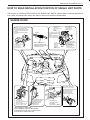
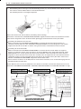
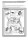
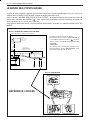
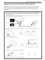
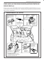
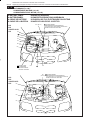
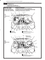
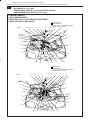
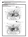
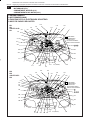
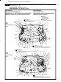
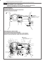
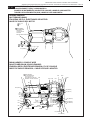
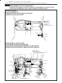
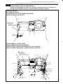
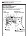
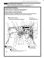
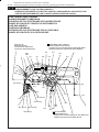
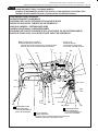
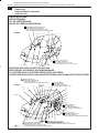
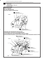
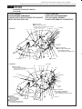
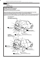
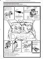
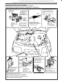
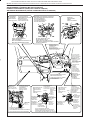
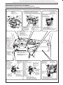
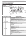
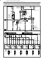
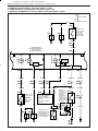
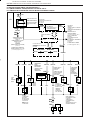
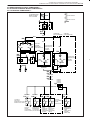
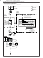
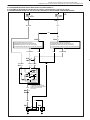
HOW TO READ INSTALLATION POSITION OF SINGLE UNIT PARTS
The diagram in "INSTALLATION POSITION OF SINGLE UNIT PARTS" section shows installation positions of
fuse, relays and control units used in this vehicle. They are illustrated as shown below.
ENGINE ROOM

8A-1-12 HOW TO USE THIS MANUAL
171110
98
23
BLK
H
L
M
12
BLK BLK
YEL/RED
YEL/RED
15A
G27
4
WASHER SWITCH
WASCHERSCHALTER
COMMANDE DE LAVE-GLACE
INTERRUPTOR DEL LAVADOR
WIPER. WASHER
FUSE BOX
SICHERUNGSKASTEN
BOÎTIER À FUSIBLES
CAJA DE FUSIBLES
COMBINATION SWITCH
KOMBINATIONSSCHALTER
COMMUTATEUR COMBINÉ
INTERRUPTOR DE COMBINACIÓN
WASHER MOTOR
WASCHERMOTOR
MOTEUR DE LAVE-GLACE
MOTOR DEL LAVADOR
FRONT WIPER & WASHER
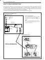
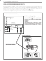
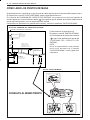
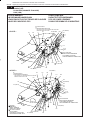
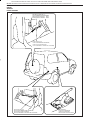
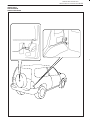
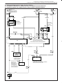
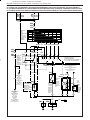
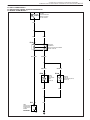
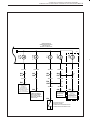
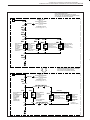
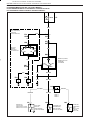
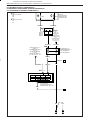
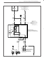
HOW TO READ GROUND POINT
Ground point means the position where the negative harness among wiring harnesses is grounded. The diagram
in "GROUND POINT" section shows such ground points. In "SYSTEM CIRCUIT DIAGRAM" section, there are
many ground marks followed by black circles with numerical figures in them (
) which mean that the end of the
harness with such black circle is grounded to some part of the vehicle.
To locate the ground point (installation position), refer to "GROUND POINT" section.
[How to locate ground point]
Look in "GROUND POINT" section for the black
circle with the same numerical figure(
)as the
described one in "SYSTEM CIRCUIT DIAGRAM"
section.
NOTE:
If there is an electrical part whose ground point is
not found in "GROUND POINT" section, that part
itself serves as a ground.
"SYSTEM CIRCUIT DIAGRAM" section
"GROUND POINT" section
CROSS-REFERENCE

8A-6-13HOW TO USE THIS MANUAL 8A-1-13
RED/YEL
WHT
10A
TAIL
OFF
HEAD
8
9
G30
FUSE BOX
SICHERUNGSKASTEN
BOITIER A FUSIBLES
CAJA DE FUSIBLES
TAIL.STOP
COMBINATION SWITCH
(LIGHTING SWITCH)
KOMBINATIONSSCHALTER
(LICHTSCHALTER)
COMMUTATEUR COMBINE
(COMMUTATEUR DE FEU)
INTERRUPTOR DE COMBINACI N
(INTERRUPTOR DE LAS LUCES)
SYSTEM CIRCUIT DIAGRAM
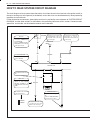
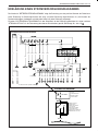
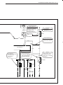
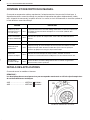
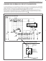
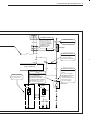
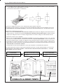
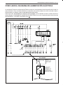
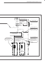
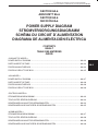
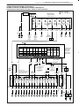
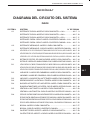
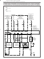
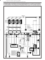
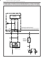
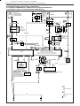
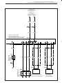
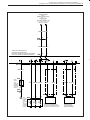
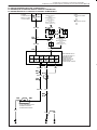
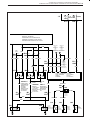
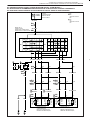
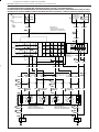
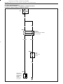
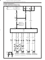
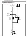
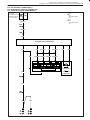
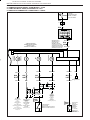
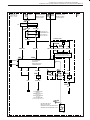
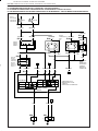
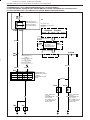
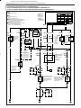
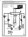
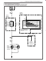
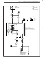
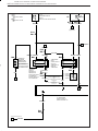
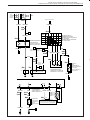
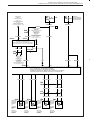
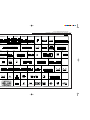
HOW TO READ POWER SUPPLY DIAGRAM
Power Supply Diagram shows the circuit from the positive terminal of the battery to each fuse in the box and
where each fuse is connected (each system circuit name). In addition, the electric load value of each fuse is
indicated.
Since every "SYSTEM CIRCUIT DIAGRAM" is drawn from the circuit down the fuse, cross-refer to "POWER
SUPPLY DIAGRAM" for the continuity of the upper circuit referring to Fuse No. such as
.
POWER SUPPLY DIAGRAM
Connection to the system is indicated.
FUSE BOX
BLK
BLK
WHT
WHT/BLK WHT/RED BLK/RED RED WHT/BLK WHT/YEL
BLK
BLK BLK WHT RED YEL LT GRNGRN WHT/GRN
WHT/BLK YEL/BLU YEL/GRN PNK/BLK YEL/BLK
YEL/BLK
YEL/BLK
BLU
BLU/BLK
BLK/BLU
BLK/RED
WHT/BLK
BLU/RED
WHT/BLK

8A-1-14 HOW TO USE THIS MANUAL
BLU
BLU
GRN/RED
YEL
GRN/BLK
ORN
WHT
BLK
BLK
256 4
E33 1 E34
7
5
A
1
SENSOR
COMBINATION
METER
(REED)
FUSE BOX
3
15A
1
5
2
6
1
2
8
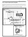
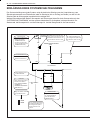
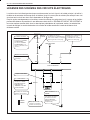
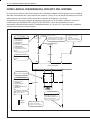
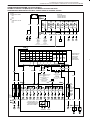
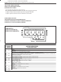
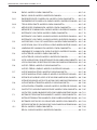
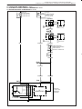
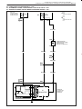
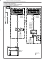
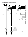
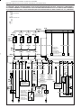
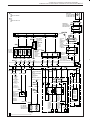
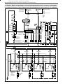
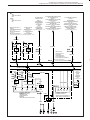
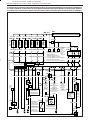
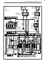
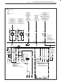
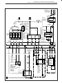
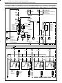
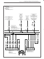
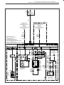
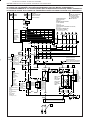
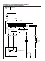
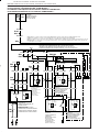
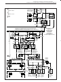
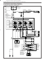
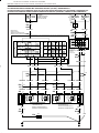
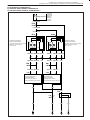
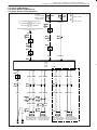
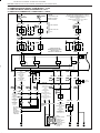
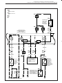
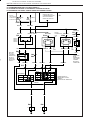
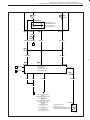
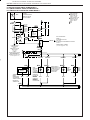
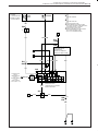
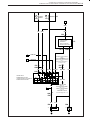
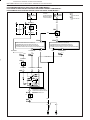
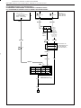
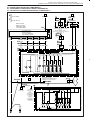
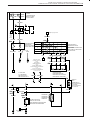
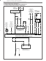
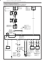
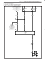
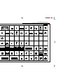
HOW TO READ SYSTEM CIRCUIT DIAGRAM
The circuit diagram of each system shows the electric circuit from the main fuse, fuse box or the ignition switch (at
the top in the diagram) to the ground (at the bottom) so that the circuit can be followed easily when performing
inspection and service work.
Further information on connector, ground point and fuses is provided by cross-reference of "SYSTEM CIRCUIT
DIAGRAM" and the other sections as described in the preceding indications of this section. Connector code,
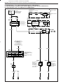
ground No. and fuse No. are the reference code for cross-reference.
This indicates the ground
No.
(Refer to "GROUND POINT"
section for the location.)
GROUND POINT
This indicates the variations
by the specifications
This indicates the wire color.
(Refer to item "WIRE
COLOR SYMBOLS" in
"HOW TO USE THIS SEC-
TION".)
Wire color
This indicates that the con-
nector is identical.
Connector mark
This No. indicates the refer-
ence code to "POWER SUP-
PLY DIAGRAM"
(Refer to "POWER SUPPLY
DIAGRAM" for the continuity
of the upper circuit.)
Fuse No.
This indicates that the shield
wire.
This indicates that the circuit
is continued to the same
symbol in the other page.
Variations by specifications
are identified by codes. For
the details, refer to the lower
left of this page.
This indicates continuity be-
tween pages, i.e., to be con-
tinued to the same symbol in
the other page.
CONTROL UNIT
1 4-DOOR
2 2-DOOR

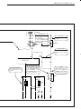
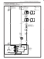
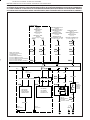
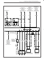
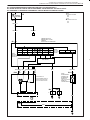
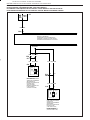
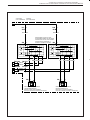
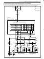
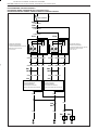
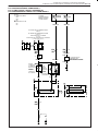
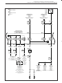
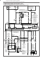
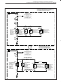
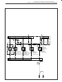
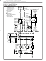
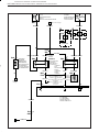
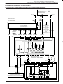
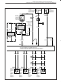
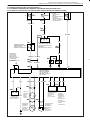
8A-6-15HOW TO USE THIS MANUAL 8A-1-15
This indicates variation of
circuit depending on speci-
fications.
Symbol marks are used for
better legibility.
For more information, refer
to item "SYMBOLS AND
MARKS" in "HOWa TO USE
THIS SECTION".
Symbola mark
This indicates the reference
code to "CONNECTOR LAY-
OUT DIAGRAM" or "LIST
OF CONNECTOR" section
for further information.
Connector code
CONTROL UNIT
This indicates the color of
the wire.
Wire color
This indicates that the inter-
mediate connector is identi-
cal.
Identical marks
This indicates the pin No.
(Refer to "LaIST OF CON-
NECTOR" section for the pin
position in the connector.)
Pina No.
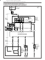
SWITCH
6
E34
1
GRN
GRN
YEL
43
E08
2
1
BLK/RED ORN
GRN
E34
C06
2
1
GRN GRN
GRN
C26
2
1
BLK
5
BLK
RED BRN/RED
E52
1
2
E52
1
BRN/RED
2
BRN/RED BRN/RED
1
A
2
1
C40
G/B
SOLENOID
1
15A
6
20A
MAIN
RELAY
MOTOR
M
M
ON
OFF
1 2
FUSE BOX
1655

8A-1-16 HOW TO USE THIS MANUAL
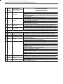
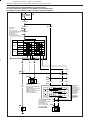
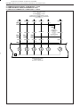
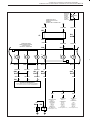
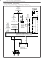
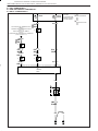
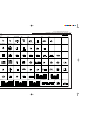
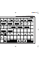
HOW TO READ LIST OF CONNECTORS
"LIST OF CONNECTORS" section is provided to help identification when looking for the connector in question
out of similar ones as well as for retrieval for positions of pins in the connector when checking continuity between
pins, etc. Please note that the list is drawn to symbolize the basic configurations of the connectors and some
connectors in the list may discrepant to the actual ones depending on the specifications.
How to Use List of Connectors :
It is easily possible to find the shape of the connector in question and its pin positions by locating the same
connector code and the pin Nos. as those in "SYSTEM CIRCUIT DIAGRAM" section from "LIST OF CONNEC-
TORS" section.
For further information on its use, refer to item "INDICATION OF CONNECTORS AND HOW TO READ THEM" in
this section.
Seite wird geladen ...
Seite wird geladen ...
Seite wird geladen ...
Seite wird geladen ...
Seite wird geladen ...
Seite wird geladen ...
Seite wird geladen ...
Seite wird geladen ...
Seite wird geladen ...
Seite wird geladen ...
Seite wird geladen ...
Seite wird geladen ...
Seite wird geladen ...
Seite wird geladen ...
Seite wird geladen ...
Seite wird geladen ...
Seite wird geladen ...
Seite wird geladen ...
Seite wird geladen ...
Seite wird geladen ...
Seite wird geladen ...
Seite wird geladen ...
Seite wird geladen ...
Seite wird geladen ...
Seite wird geladen ...
Seite wird geladen ...
Seite wird geladen ...
Seite wird geladen ...
Seite wird geladen ...
Seite wird geladen ...
Seite wird geladen ...
Seite wird geladen ...
Seite wird geladen ...
Seite wird geladen ...
Seite wird geladen ...
Seite wird geladen ...
Seite wird geladen ...
Seite wird geladen ...
Seite wird geladen ...
Seite wird geladen ...
Seite wird geladen ...
Seite wird geladen ...
Seite wird geladen ...
Seite wird geladen ...
Seite wird geladen ...
Seite wird geladen ...
Seite wird geladen ...
Seite wird geladen ...
Seite wird geladen ...
Seite wird geladen ...
Seite wird geladen ...
Seite wird geladen ...
Seite wird geladen ...
Seite wird geladen ...
Seite wird geladen ...
Seite wird geladen ...
Seite wird geladen ...
Seite wird geladen ...
Seite wird geladen ...
Seite wird geladen ...
Seite wird geladen ...
Seite wird geladen ...
Seite wird geladen ...
Seite wird geladen ...
Seite wird geladen ...
Seite wird geladen ...
Seite wird geladen ...
Seite wird geladen ...
Seite wird geladen ...
Seite wird geladen ...
Seite wird geladen ...
Seite wird geladen ...
Seite wird geladen ...
Seite wird geladen ...
Seite wird geladen ...
Seite wird geladen ...
Seite wird geladen ...
Seite wird geladen ...
Seite wird geladen ...
Seite wird geladen ...
Seite wird geladen ...
Seite wird geladen ...
Seite wird geladen ...
Seite wird geladen ...
Seite wird geladen ...
Seite wird geladen ...
Seite wird geladen ...
Seite wird geladen ...
Seite wird geladen ...
Seite wird geladen ...
Seite wird geladen ...
Seite wird geladen ...
Seite wird geladen ...
Seite wird geladen ...
Seite wird geladen ...
Seite wird geladen ...
Seite wird geladen ...
Seite wird geladen ...
Seite wird geladen ...
Seite wird geladen ...
Seite wird geladen ...
Seite wird geladen ...
Seite wird geladen ...
Seite wird geladen ...
Seite wird geladen ...
Seite wird geladen ...
Seite wird geladen ...
Seite wird geladen ...
Seite wird geladen ...
Seite wird geladen ...
Seite wird geladen ...
Seite wird geladen ...
Seite wird geladen ...
Seite wird geladen ...
Seite wird geladen ...
Seite wird geladen ...
Seite wird geladen ...
Seite wird geladen ...
Seite wird geladen ...
Seite wird geladen ...
Seite wird geladen ...
Seite wird geladen ...
Seite wird geladen ...
Seite wird geladen ...
Seite wird geladen ...
Seite wird geladen ...
Seite wird geladen ...
Seite wird geladen ...
Seite wird geladen ...
Seite wird geladen ...
Seite wird geladen ...
Seite wird geladen ...
Seite wird geladen ...
Seite wird geladen ...
Seite wird geladen ...
Seite wird geladen ...
Seite wird geladen ...
Seite wird geladen ...
Seite wird geladen ...
Seite wird geladen ...
Seite wird geladen ...
Seite wird geladen ...
Seite wird geladen ...
Seite wird geladen ...
Seite wird geladen ...
Seite wird geladen ...
Seite wird geladen ...
Seite wird geladen ...
Seite wird geladen ...
Seite wird geladen ...
Seite wird geladen ...
Seite wird geladen ...
Seite wird geladen ...
Seite wird geladen ...
Seite wird geladen ...
Seite wird geladen ...
Seite wird geladen ...
Seite wird geladen ...
Seite wird geladen ...
Seite wird geladen ...
Seite wird geladen ...
Seite wird geladen ...
Seite wird geladen ...
Seite wird geladen ...
Seite wird geladen ...
Seite wird geladen ...
Seite wird geladen ...
Seite wird geladen ...
Seite wird geladen ...
Seite wird geladen ...
Seite wird geladen ...
Seite wird geladen ...
Seite wird geladen ...
Seite wird geladen ...
Seite wird geladen ...
Seite wird geladen ...
Seite wird geladen ...
Seite wird geladen ...
Seite wird geladen ...
Seite wird geladen ...
Seite wird geladen ...
Seite wird geladen ...
Seite wird geladen ...
Seite wird geladen ...
Seite wird geladen ...
Seite wird geladen ...
Seite wird geladen ...
Seite wird geladen ...
Seite wird geladen ...
Seite wird geladen ...
Seite wird geladen ...
Seite wird geladen ...
Seite wird geladen ...
Seite wird geladen ...
Seite wird geladen ...
Seite wird geladen ...
Seite wird geladen ...
Seite wird geladen ...
Seite wird geladen ...
Seite wird geladen ...
Seite wird geladen ...
Seite wird geladen ...
Seite wird geladen ...
Seite wird geladen ...
Seite wird geladen ...
Seite wird geladen ...
Seite wird geladen ...
Seite wird geladen ...
Seite wird geladen ...
Seite wird geladen ...
Seite wird geladen ...
Seite wird geladen ...
Seite wird geladen ...
Seite wird geladen ...
Seite wird geladen ...
Seite wird geladen ...
Seite wird geladen ...
Seite wird geladen ...
Seite wird geladen ...
Seite wird geladen ...
Seite wird geladen ...
Seite wird geladen ...
Seite wird geladen ...
Seite wird geladen ...
Seite wird geladen ...
Seite wird geladen ...
Seite wird geladen ...
Seite wird geladen ...
Seite wird geladen ...
Seite wird geladen ...
Seite wird geladen ...
Seite wird geladen ...
Seite wird geladen ...
Seite wird geladen ...
Seite wird geladen ...
Seite wird geladen ...
Seite wird geladen ...
Seite wird geladen ...
Seite wird geladen ...
Seite wird geladen ...
Seite wird geladen ...
Seite wird geladen ...
Seite wird geladen ...
Seite wird geladen ...
Seite wird geladen ...
Seite wird geladen ...
-
 1
1
-
 2
2
-
 3
3
-
 4
4
-
 5
5
-
 6
6
-
 7
7
-
 8
8
-
 9
9
-
 10
10
-
 11
11
-
 12
12
-
 13
13
-
 14
14
-
 15
15
-
 16
16
-
 17
17
-
 18
18
-
 19
19
-
 20
20
-
 21
21
-
 22
22
-
 23
23
-
 24
24
-
 25
25
-
 26
26
-
 27
27
-
 28
28
-
 29
29
-
 30
30
-
 31
31
-
 32
32
-
 33
33
-
 34
34
-
 35
35
-
 36
36
-
 37
37
-
 38
38
-
 39
39
-
 40
40
-
 41
41
-
 42
42
-
 43
43
-
 44
44
-
 45
45
-
 46
46
-
 47
47
-
 48
48
-
 49
49
-
 50
50
-
 51
51
-
 52
52
-
 53
53
-
 54
54
-
 55
55
-
 56
56
-
 57
57
-
 58
58
-
 59
59
-
 60
60
-
 61
61
-
 62
62
-
 63
63
-
 64
64
-
 65
65
-
 66
66
-
 67
67
-
 68
68
-
 69
69
-
 70
70
-
 71
71
-
 72
72
-
 73
73
-
 74
74
-
 75
75
-
 76
76
-
 77
77
-
 78
78
-
 79
79
-
 80
80
-
 81
81
-
 82
82
-
 83
83
-
 84
84
-
 85
85
-
 86
86
-
 87
87
-
 88
88
-
 89
89
-
 90
90
-
 91
91
-
 92
92
-
 93
93
-
 94
94
-
 95
95
-
 96
96
-
 97
97
-
 98
98
-
 99
99
-
 100
100
-
 101
101
-
 102
102
-
 103
103
-
 104
104
-
 105
105
-
 106
106
-
 107
107
-
 108
108
-
 109
109
-
 110
110
-
 111
111
-
 112
112
-
 113
113
-
 114
114
-
 115
115
-
 116
116
-
 117
117
-
 118
118
-
 119
119
-
 120
120
-
 121
121
-
 122
122
-
 123
123
-
 124
124
-
 125
125
-
 126
126
-
 127
127
-
 128
128
-
 129
129
-
 130
130
-
 131
131
-
 132
132
-
 133
133
-
 134
134
-
 135
135
-
 136
136
-
 137
137
-
 138
138
-
 139
139
-
 140
140
-
 141
141
-
 142
142
-
 143
143
-
 144
144
-
 145
145
-
 146
146
-
 147
147
-
 148
148
-
 149
149
-
 150
150
-
 151
151
-
 152
152
-
 153
153
-
 154
154
-
 155
155
-
 156
156
-
 157
157
-
 158
158
-
 159
159
-
 160
160
-
 161
161
-
 162
162
-
 163
163
-
 164
164
-
 165
165
-
 166
166
-
 167
167
-
 168
168
-
 169
169
-
 170
170
-
 171
171
-
 172
172
-
 173
173
-
 174
174
-
 175
175
-
 176
176
-
 177
177
-
 178
178
-
 179
179
-
 180
180
-
 181
181
-
 182
182
-
 183
183
-
 184
184
-
 185
185
-
 186
186
-
 187
187
-
 188
188
-
 189
189
-
 190
190
-
 191
191
-
 192
192
-
 193
193
-
 194
194
-
 195
195
-
 196
196
-
 197
197
-
 198
198
-
 199
199
-
 200
200
-
 201
201
-
 202
202
-
 203
203
-
 204
204
-
 205
205
-
 206
206
-
 207
207
-
 208
208
-
 209
209
-
 210
210
-
 211
211
-
 212
212
-
 213
213
-
 214
214
-
 215
215
-
 216
216
-
 217
217
-
 218
218
-
 219
219
-
 220
220
-
 221
221
-
 222
222
-
 223
223
-
 224
224
-
 225
225
-
 226
226
-
 227
227
-
 228
228
-
 229
229
-
 230
230
-
 231
231
-
 232
232
-
 233
233
-
 234
234
-
 235
235
-
 236
236
-
 237
237
-
 238
238
-
 239
239
-
 240
240
-
 241
241
-
 242
242
-
 243
243
-
 244
244
-
 245
245
-
 246
246
-
 247
247
-
 248
248
-
 249
249
-
 250
250
-
 251
251
-
 252
252
-
 253
253
-
 254
254
-
 255
255
-
 256
256
-
 257
257
-
 258
258
-
 259
259
-
 260
260
-
 261
261
-
 262
262
-
 263
263
-
 264
264
-
 265
265
-
 266
266


Suzuki Canvas SQ420 Bedienungsanleitung
- Typ
- Bedienungsanleitung
- Dieses Handbuch eignet sich auch für
in anderen Sprachen
- English: Suzuki Canvas SQ420 Owner's manual
Verwandte Artikel
Andere Dokumente
-
Q Acoustics E120 Benutzerhandbuch
-
TowSmart 1402 Installationsanleitung
-
-
Respekta Petunia Küchenzeilen Installationsanleitung
-
Dell Canvas 27 Benutzerhandbuch
-
Pitco Frialator SGH50 Benutzerhandbuch
-
Arke K03071 Installationsanleitung
-
Giacomini R279B Bedienungsanleitung
-
-
Follett Ice Pro EDB1000 Installation and Service Manual