
DI51 463 10
Montageanleitung
Installation manual
G463
Integral Doppelscheinwerfereinsätze LHD
Integral four headlamp inserts LHD
Modell 2003 ab 06.2002
from year 06.2002
Stand 16.12.2003
dated from 2003-12-16
Technische Änderungen vorbehalten
specifications are subject to change
Seite 1/4
side 1/4
Artikelnummer / part number:
Artikelbezeichnung / designation:
Modell / model:
Arbeitsablauf:
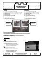
Bild 1:
1. Stoßstange demontieren und säubern,
vorhandene Nebelscheinwerfer demontieren.
2. Schnitt und Bohrschablone zuschneiden.
- Kante A an Stossstangenecke anlegen
- Schablone mit Klebeband fixieren
fig.1:
1. Dismantle and clean the bumper,
deinstallation of existing fog lamp system.
2. Cut the drilling template and the cut.
- apply edge A to the bumper corner
- fix the drilling template with tape.
Bild 1
A
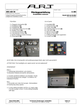
Stückliste:
2 x Frontblende links (1a) und rechts (1b)
2 x Nebelscheinwerfer Halogen links (2a) und rechts (2b)
2 x Fernscheinwerfer Halogen links (3a) und rechts (3b)
1 x Kabelbaum (4)
6 x Kabelbinder (5)
8 x Unterlegscheiben 6,4x20mm (6)
8 x Muttern 6mm (7)
2 x Flachsteckerhülsen (8)
4 x Flachstecker 6,3mm (9)
1 x Bohrschablone (siehe Anhang)
List of parts:
2 x front mask left (1a) and right (1b)
2 x fog lamps halogen left (2a) and right (2b)
2 x high beams halogen left (3a) and right (3b)
1 x wiring harness (4)
6 x cable strap (5)
8 x wearing parts 6,4x20mm (6)
8 x nuts 6mm (7)
2 x flat pin housing (8)
4 x flat pin 6,3mm (9)
1 x drilling template (see appendix)
1
ACHTUNG, wichtiger Hinweis:
Die Scheinwerfer sind spritzwassergeschützt, aber nicht wasserdicht!
ATTENTION, important note:
The headlights are splash-proof, but not waterproof!
(1b)
Links / left
DI51 463 11
Rechts /
right
DI51 463 12
(1a)
(2a)
(2b)
(3a)
(3b)
(4)
(5)
(6)
(7)
(8)
(9)
(1b)

DI51 463 10
Montageanleitung
Installation manual
G463
Integral Doppelscheinwerfereinsätze LHD
Integral four headlamp inserts LHD
Modell 2003 ab 06.2002
from year 06.2002
Stand 16.12.2003
dated from 2003-12-16
Technische Änderungen vorbehalten
specifications are subject to change
Seite 2/4
side 2/4
Artikelnummer / part number:
Artikelbezeichnung / designation:
Modell / model:
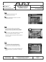
Bild 2:
3. Schnittkanten anzeichnen und mit
Druckluftsäge ausschneiden.
fig.2:
3. Draw the cutting edge and then cut out with
compressed air saw.
Bild 3:
4. Anhand der Bohrschablone die benötigten
Löcher anzeichnen und mittels Körner anreißen.
Führungen für die Stehbolzen Ø 6,5mm bohren.
fig.3:
4. Mark on basis of the drilling template the necessary
holes and scribe them by means of grains.
Bore with a 6,5mm strong metal drill the guidance
for the staybolts
Bild 4:
5. An der hinteren Seite der Stoßstange die
Aussparungen für die Doppelscheinwerfer
anzeichnen. (Auf ausreichend Platz achten)
fig. 4:
5. Mark the recesses for the double headlights at the
back of the bumper. (pay attention to sufficiently
place)
Bild 2
Bild 3
Bild 4

DI51 463 10
Montageanleitung
Installation manual
G463
Integral Doppelscheinwerfereinsätze LHD
Integral four headlamp inserts LHD
Modell 2003 ab 06.2002
from year 06.2002
Stand 16.12.2003
dated from 2003-12-16
Technische Änderungen vorbehalten
specifications are subject to change
Seite 3/4
side 3/4
Artikelnummer / part number:
Artikelbezeichnung / designation:
Modell / model:
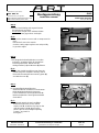
Bild 6:
7. Die Doppelscheinwerferblende von außen
aufsetzen, gegebenenfalls die Stehbolzen
vorsichtig ausrichten. Blende mit den
Beilagscheiben ( 4) und Muttern (5) fixieren.
fig. 6:
7. Attach the double headlight screen from the
outside (align the staybolts carefully) and fix
them with the attached 6mm wearing parts (4)
and with the nuts (5)
Bild 5
Steg B
Bild 6
Stoßstangenecke
Bumper corner
Bild 5:
6. Mit der Druckluftsäge die angezeichneten
Aussparungen aussägen.
ACHTUNG! Steg B muss erhalten bleiben.
Auschnittkanten gegen Rost versiegeln.
fig. 5:
6. Saw-out the drawn recesses with a compressed air
saw.
NOTE! Bar B must also remain.
Seal the cutting edges against rust and possibly
in-grow the edges.
Bild 7:
8. Kunststoffgewindeaufsätze der
Stellschrauben C anwärmen und einsetzen.
Beide Doppelscheinwerfer einsetzen.
Fernscheinwerfer Fahrzeugaußenseite A ,
Nebelscheinwerfer Fahrzeuginnenseite B.
Siehe Bild 7.
fig. 7:
8. Afterwards attach the two headlights.
Install the high beam on the vehicle
exterior side A, install the fog lamp on the
vehicle interior side B. Warm up the
plastic-clips for the headlight adjusting
screws C and set it in.
See figure 7.
Bild 7
Nebelscheinwerfer
Fog beam
Fernscheinwerfer
High beam
C
A
B

DI51 463 10
Montageanleitung
Installation manual
G463
Integral Doppelscheinwerfereinsätze LHD
Integral four headlamp inserts LHD
Modell 2003 ab 06.2002
from year 06.2002
Stand 16.12.2003
dated from 2003-12-16
Technische Änderungen vorbehalten
specifications are subject to change
Seite 4/4
side 4/4
Artikelnummer / part number:
Artikelbezeichnung / designation:
Modell / model:
tuning gmbh - Am Keuper 3 - 90475 Nürnberg - Germany
Telephone +49(0)9128 -92500 Fax +49(0)9128 -920502 info@ART-tuning.com www.ART-tuning.com
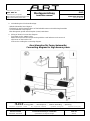
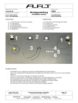
9. Verkabelung der Scheinwerferanlage:
- Nebelscheinwerfer innen liegend.
Flachstecker und Flachsteckhülsen auf Serienkabel setzen und Verbindung herstellen.
- Fernscheinwerfer innen liegend.
Mit Leitungssatz gemäß Anschlussplan (unten) verdrahten.
9. Wiring of electrical connection diagram:
- Fog lamps on the interior r side.
Attach the flat pin and the flat pin housing with the serial wireness and connect it.
- High beam on the interior side.
Connect it according the connecting diagram.
Anschlussplan für Fernscheinwerfer:
Connecting diagram for high beam system:
-
 1
1
-
 2
2
-
 3
3
-
 4
4


in anderen Sprachen
- English: Art G463 Installation guide
Verwandte Artikel
Andere Dokumente
-
 A.R.T. DI01 463 30 Installationsanleitung
-
 A.R.T. W463 Installationsanleitung
-
 Christopeit Sport CXM 6 Bedienungsanleitung
-
Delta LHD 43,43-1 Line Extender Benutzerhandbuch
-
Bosch HTD 6 Series Original Instructions Manual
-
Suzuki Canvas SQ420 Bedienungsanleitung
-
Ferrari F512 TR Technical Manual
-
ESAB LHD 250 Benutzerhandbuch


