MSI G52-75131X4 Bedienungsanleitung
- Kategorie
- Motherboards
- Typ
- Bedienungsanleitung
Dieses Handbuch eignet sich auch für

i
P45D3 Platinum Series
MS-7513(V1.X) Mainboard
G52-75131X4

ii
Copyright Notice
The material in this document is the intellectual property of MICRO-STAR
INTERNATIONAL. We take every care in the preparation of this document, but no
guarantee is given as to the correctness of its contents. Our products are under
continual improvement and we reserve the right to make changes without notice.
Trademarks
All trademarks are the properties of their respective owners.
NVIDIA, the NVIDIA logo, DualNet, and nForce are registered trademarks or trade-
marks of NVIDIA Corporation in the United States and/or other countries.
AMD, Athlon™, Athlon™ XP, Thoroughbred™, and Duron™ are registered trade-
marks of AMD Corporation.
Intel
®
and Pentium
®
are registered trademarks of Intel Corporation.
PS/2 and OS
®
/2 are registered trademarks of International Business Machines
Corporation.
Windows
®
95/98/2000/NT/XP are registered trademarks of Microsoft Corporation.
Netware
®
is a registered trademark of Novell, Inc.
Award
®
is a registered trademark of Phoenix Technologies Ltd.
AMI
®
is a registered trademark of American Megatrends Inc.
Revision History
Revision Revision History Date
V1.0 P45D3 Platinum first release April 2008
for Europe
Technical Support
If a problem arises with your system and no solution can be obtained from the user’s
manual, please contact your place of purchase or local distributor. Alternatively,
please try the following help resources for further guidance.
Visit the MSI website for FAQ, technical guide, BIOS updates, driver updates,
and other information: http://global.msi.com.tw/index.php?
func=faqIndex
Contact our technical staff at: http://support.msi.com.tw/

iii
Safety Instructions
CAUTION: Danger of explosion if battery is incorrectly replaced.
Replace only with the same or equivalent type recommended by the
manufacturer.
1. Always read the safety instructions carefully.
2. Keep this User’s Manual for future reference.
3. Keep this equipment away from humidity.
4. Lay this equipment on a reliable flat surface before setting it up.
5. The openings on the enclosure are for air convection hence protects the equip-
ment from overheating. DO NOT COVER THE OPENINGS.
6. Make sure the voltage of the power source and adjust properly 110/220V be-
fore connecting the equipment to the power inlet.
7. Place the power cord such a way that people can not step on it. Do not place
anything over the power cord.
8. Always Unplug the Power Cord before inserting any add-on card or module.
9. All cautions and warnings on the equipment should be noted.
10. Never pour any liquid into the opening that could damage or cause electrical
shock.
11. If any of the following situations arises, get the equipment checked by a service
personnel:
† The power cord or plug is damaged.
† Liquid has penetrated into the equipment.
† The equipment has been exposed to moisture.
† The equipment has not work well or you can not get it work according to
User’s Manual.
† The equipment has dropped and damaged.
† The equipment has obvious sign of breakage.
12. DO NOT LEAVE THIS EQUIPMENT IN AN ENVIRONMENT UNCONDITIONED, STOR-
AGE TEMPERATURE ABOVE 60
0
C (140
0
F), IT MAY DAMAGE THE EQUIPMENT.

iv
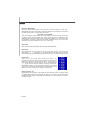
FCC-B Radio Frequency Interference Statement
This equipment has been
tested and found to comply
with the limits for a Class B
digital device, pursuant to Part
15 of the FCC Rules. These limits are designed to provide reasonable protection
against harmful interference in a residential installation. This equipment generates,
uses and can radiate radio frequency energy and, if not installed and used in accor-
dance with the instructions, may cause harmful interference to radio communications.
However, there is no guarantee that interference will not occur in a particular
installation. If this equipment does cause harmful interference to radio or television
reception, which can be determined by turning the equipment off and on, the user is
encouraged to try to correct the interference by one or more of the measures listed
below.
† Reorient or relocate the receiving antenna.
† Increase the separation between the equipment and receiver.
† Connect the equipment into an outlet on a circuit different from that to
which the receiver is connected.
† Consult the dealer or an experienced radio/television technician for help.
Notice 1
The changes or modifications not expressly approved by the party responsible for
compliance could void the user’s authority to operate the equipment.
Notice 2
Shielded interface cables and A.C. power cord, if any, must be used in order to
comply with the emission limits.
VOIR LA NOTICE D ’INSTALLATION AVANT DE RACCORDER AU RESEAU.
Micro-Star International
MS-7353
This device complies with Part 15 of the FCC Rules. Operation is subject to the
following two conditions:
(1) this device may not cause harmful interference, and
(2) this device must accept any interference received, including interference that
may cause undesired operation.

v
WEEE (Waste Electrical and Electronic Equipment) Statement

vi

vii

viii
CONTENTS
Copyright Notice.........................................................................................................ii
Trademarks..................................................................................................................ii
Revision History.........................................................................................................ii
Technical Support......................................................................................................ii
Safety Instructions...................................................................................................iii
FCC-B Radio Frequency Interference Statement.............................................iv
WEEE (Waste Electrical and Electronic Equipment) Statement.......................v
English......................................................................................................................En-1
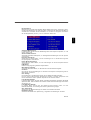
Specifications....................................................................................................En-2
Central Processing Unit: CPU...........................................................................En-5
Memory...............................................................................................................En-7
Connectors, Jumpers, Slots.............................................................................En-9
Back Panel........................................................................................................En-19
BIOS Setup.......................................................................................................En-23
Software Information......................................................................................En-27
Deutsch....................................................................................................................De-1
Spezifikationen..................................................................................................De-2
Hauptprozessor: CPU.......................................................................................De-5
Speicher.............................................................................................................De-7
Anschlüsse, Steckbrücken und Slots.............................................................De-9
Hinteres Anschlusspaneel.............................................................................De-19
BIOS Setup.......................................................................................................De-23
Software-Information......................................................................................De-27
Français.....................................................................................................................Fr-1
Spécificités.........................................................................................................Fr-2
Central Processing Unit: CPU............................................................................Fr-5
Mémoire...............................................................................................................Fr-7
Connecteurs, Cavaliers, Slots..........................................................................Fr-9
Panneau Arrière...............................................................................................Fr-19
Configuration du BIOS......................................................................................Fr-23
Information de Logiciel.....................................................................................Fr-27
Русский ....................................................................................................................Ru-1
Характеристики ...............................................................................................Ru-2
Центральный процессор (CPU).....................................................................Ru-5
Память ..............................................................................................................Ru-7
Коннекторы, перемычки, разъемы..............................................................Ru-9
Задняя панель ...............................................................................................Ru-19
Настройка BIOS..............................................................................................Ru-23
Сведения о программном обеспечении ...................................................Ru-27

En-1
English
P45D3 Platinum
User’s Guide
English

En-2
MS-7513 Mainboard
Specifications
Processor Support
- Intel
®
Core
TM
2 Extreme/Quad/Duo, Pentium
®
Dual-Core and
Celeron
®
processors in the LGA775 package
- Support Intel
®
Yorkfield, Wolfdale
- Support Conroe family and up
(For the latest information about CPU, please visit http://global.
msi.com.tw/index.php?func=cpuform)
Supported FSB
- 1333/1066/800 MHz and up
Chipset
- North Bridge: Intel
®
Eaglelake P45 chipset
- South Bridge: Intel
®
ICH10R/9R(optional) chipset
Memory Support
- 4 DDR3 DIMMs support DDR3 1333/1066/800 MHz SDRAM and
up (240pin / 1.5V / 8GB Max)
(For more information on compatible components, please visit
http://global.msi.com.tw/index.php?func=testreport)
LAN
- Supports PCIE LAN 10/100/1000 Fast Ethernet by Realtek 8111C
Audio
- Chip integrated by Realtek
®
ALC888/ALC888T
- Flexible 8-channel audio with jack sensing
- Compliant with Azalia 1.0 Spec
- Meet Microsoft Vista Premium spec
- Supports VoIP Card (only for ALC888T)
IDE
- 1 IDE port (only for Jmicron 363)
- Supports Ultra DMA 66/100/133 mode
- Supports PIO, Bus Master operation mode
SATA
- 6 SATAII ports by ICH10R/ICH9R(optional)
- 2 SATA II port by Jmicron 363
- 1 eSATA port by Jmicron 362
- Supports storage and data transfers at up to 3Gb/s
RAID
- Supports Intel Martix Storage Technology (AHCI + RAID 0/1/5/10)
by ICH10R/ICH9R(optional)
IEEE1394
- Chip integrated by Jmicron 381
- Transfer rate is up to 400Mbps
- Supports up to 2 ports (rear x 1, front x 1 port. Manually check if

En-3
English
the memory module has been locked in place by the DIMM slot clips
at the sides.)
FDD
- 1 floppy port
- Supports 1 FDD with 360KB, 720KB, 1.2MB, 1.44MB and 2.88MB
Connectors
Back panel
- 1 PS/2 mouse port
- 1 PS/2 keyboard port
- 1 eSATA port (support Command Based Port Multipliers)
- 6 USB 2.0 Ports
- 1 LAN jack (10/100/1000)
- 6 flexible audio jacks
- 1 1394 port
- 1 Optical S/PDIF-Out (optional)
- 1 Clear CMOS button
On-Board Pinheaders / Connectors
- 3 USB 2.0 pinheaders
- 1 IEEE1394 pinheader
- 1 chasis intrusion connector
- 1 SPDIF-out pinheader
- 1 CD-in connector
- 1 front audio pinheader
- 1 serial port pinheader
- 1 TPM Module pinheader
- 1 power button
- 1 reset button
- 1 VoIP card pinheader (optional)
TPM
- Supports TPM
Slots
- 1 PCI Express x16 slot compatible with PCIE 2.0 spec
a. the PCIE x16 slot (PCI_E1) supports up to PCIE 2.0x16 speed
b. for CrossFire mode, please install both graphics cards on both
PCIE x16 slots
c. to use 2 PCIE x16 slots, the PCIE x 16 lanes will auto arrange
from x16/ x0 to x8/ x8
- 2 PCI Express x 1 slots
- 2 PCI slots
Form Factor
- ATX (30.5cm X 24.4cm)
Mounting
- 9 mounting holes

En-4
MS-7513 Mainboard
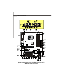
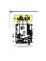
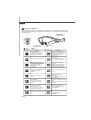
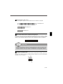
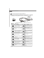
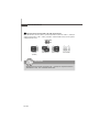
Quick Components Guide of P45D3 Platinum Series
(MS-7513 v1.X) Mainboard
3 En-7
5
En-9
7
En-10
8
En-10
25
En-16
A
En-19
H En-21
F
En-20
H
En-21
K
En-21
L En-21
N En-21
En-21
I
J
En-21
M En-21
P
En- 21
Q
En- 21
R
En-22
G
En-20
10
En-11
31
En-17
32
En-18
26
En-16
11
En-11
4 En-9
29
En-17
30 En-17
14
En-12
4
En-9
1
En-5
4
En-9
6
En-9
17
En-13
15 En-12
En-15
9
En-10
12
En-11
21
27
En-16
28
En-16
22 En-15
19
En-13

En-5
English
1
Central Processing Unit: CPU
Important
The mainboard supports Intel
®
processor. The mainboard uses a CPU socket called
Socket 775 for easy CPU installation. If you do not have the CPU cooler, consult your
dealer before turning on the computer.
For the latest information about CPU, please visit http://global.msi.com.tw/index.php?
func=cpuform
Overheating
Overheating will seriously damage the CPU and system. Always make sure the
cooling fan can work properly to protect the CPU from overheating. Make sure
that you apply an even layer of thermal paste (or thermal tape) between the CPU
and the heatsink to enhance heat dissipation.
Replaceing the CPU
While replacing the CPU, always turn off the ATX power supply or unplug the
power supply’s power cord from the grounded outlet first to ensure the safety of
CPU.
Overclocking
This mainboard is designed to support overclocking. However, please make
sure your components are able to tolerate such abnormal setting, while doing
overclocking. Any attempt to operate beyond product specifications is not
recommended. We do not guarantee the damages or risks caused by inad-
equate operation or beyond product specifications.

En-6
MS-7513 Mainboard
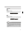
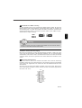
alignment key
Important
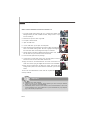
CPU & Cooler Installation Procedures for Socket 775
1. The CPU socket has a plastic cap on it to protect the contact from
damage. Before you have installed the CPU, always cover it to pro-
tect the socket pin.
2. Remove the cap from lever hinge side.
3. The pins of socket reveal.
4. Open the load lever.
5. Lift the load lever up and open the load plate.
6. After confirming the CPU direction for correct mating, put down the
CPU in the socket housing frame. Be sure to grasp on the edge of
the CPU base. Note that the alignment keys are matched.
7. Visually inspect if the CPU is seated well into the socket. If not, take
out the CPU with pure vertical motion and reinstall.
8. Cover the load plate onto the package.
9. Press down the load lever lightly onto the load plate, and then
secure the lever with the hook under retention tab.
10.Align the holes on the mainboard with the cooler. Push down the
cooler until its four clips get wedged into the holes of the mainboard.
11.Press the four hooks down to fasten the cooler. Then rotate the
locking switch (refer to the correct direction marked on it) to lock the
hooks.
12.Turn over the mainboard to confirm that the clip-ends are
correctly inserted.
1. Read the CPU status in BIOS.
2. Whenever CPU is not installed, always protect your CPU socket pin with the
plastic cap covered to avoid damaging.
3. Mainboard photos shown in this section are for demonstration of the CPU/
cooler installation only. The appearance of your mainboard may vary depend-
ing on the model you purchase.

En-7
English
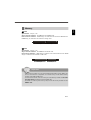
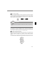
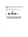
Memory
64x2=128 pin 56x2=112 pin
2
Important
3
72x2=144 pin
48x2=96 pin
DDR2
Specification : 240-pin, 1.8v.
Single channel definition : All DIMM slots are GREEN color.
Dual channels definition : DIMM slot(s) on Channel A are marked in GREEN color.
DIMM slot(s) on Channel B are marked in Orange color.
DDR3
Specification : 240-pin, 1.5v.
Single channel definition : All DIMM slots are BLUE color.
Dual channels definition : DIMM slot(s) on Channel A are marked in BLUE color. DIMM
slot(s) on Channel B are marked in PINK color.
- DDR3 memory modules are not interchangeable with DDR2 and the DDR3 stan
dard is not backwards compatible. You should always install DDR3 memory
modules in the DDR3 DIMM slots.
- In Dual-Channel mode, make sure that you install memory modules of the same
type and density in different channel DIMM slots.
- To enable successful system boot-up, always insert the memory modules into the
DIMM1 first.

En-8
MS-7513 Mainboard
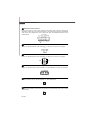
Important
Volt
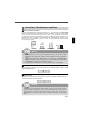
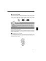
Installing Memory Modules
You can find the notch on the memory modules and the volt on the DIMM slots. Follow
the procedures below to install the memory module properly.
1.The memory modules has only one notch on the center and will only fit in the right
orientation.
2.Insert the memory module vertically into the DIMM slot. Then push it in until the
golden finger on the memory module is deeply inserted in the DIMM slot. The
plastic clip at each side of the DIMM slot will automatically close when the memory
module is properly seated.
3.Manually check if the memory module has been locked in place by the DIMM slot
clips at the sides.
You can barely see the golden finger if the memory module is properly inserted in
the DIMM slot.
Notch

En-9
English
5
4
6
Important
Important
CPUFAN
SYSFAN1/2
SYSFAN5
SE NSOR
+1 2 V
GND
CONTROL
SYSFAN3/4
SENSOR
+1 2V
GND
SENSOR
+1 2V
GND
SENSOR
+12V
GND
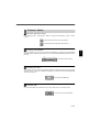
Connectors, Jumpers, Slots
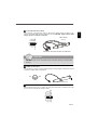
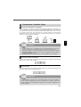
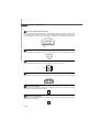
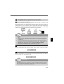
Fan Power Connectors
The fan power connectors support system cooling fan with +12V. The CPU FAN supports
Smart FAN function. When connect the wire to the connectors, always take note that the
red wire is the positive and should be connected to the +12V, the black wire is Ground
and should be connected to GND. If the mainboard has a System Hardware Monitor
chipset on-board, you must use a specially designed fan with speed sensor to take
advantage of the fan control.
1.Please refer to the recommended CPU fans at processor’s official website or
consult the vendors for proper CPU cooling fan.
2.CPUFAN supports fan control. You can install Dual Core Center utility that
will automatically control the CPU fan speed according to the actual CPU
temperature.
3. Fan cooler set with 3 or 4 pins power connector are both available for CPUFAN.
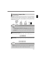
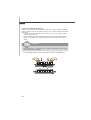
Floppy Disk Drive Connector
This connector supports 360KB, 720KB, 1.2MB, 1.44MB or 2.88MB floppy disk drive.
IDE connector
This connector supports IDE hard disk drives, optical disk drives and other IDE devices.
If you install two IDE devices on the same cable, you must configure the drives
separately to Master/ Slave mode by setting jumpers. Refer to IDE device’s docu-
mentation supplied by the vendors for jumper setting instructions.

En-10
MS-7513 Mainboard
8
9
7
Important
JFP2
7
8
Power
LED
Speaker
1
2
JFP1
9
10
Reset
Switch
Power
Switch
1
2
HDD
LED
Power
LED
IEEE1394 Bracket
(Optional)
Key(no pin)
Cablepower
TPB+
Ground
TPA+
Ground
TPB-
Cable power
Ground
TPA-
1
2
9
10
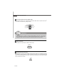
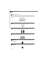
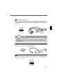
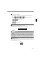
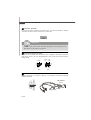
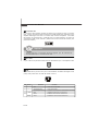
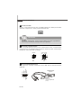
Serial ATA Connector
This connector is a high-speed Serial ATA interface port. Each connector can connect to
one Serial ATA device.
Please do not fold the Serial ATA cable into 90-degree angle. Otherwise, data
loss may occur during transmission.
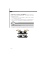
Front Panel Connectors
These connectors are for electrical connection to the front panel switches and LEDs.
The JFP1 is compliant with Intel
®
Front Panel I/O Connectivity Design Guide.
IEEE1394 Connector (Green)
This connector allows you to connect the IEEE1394 device via an optional IEEE1394
bracket.

En-11
English
10
12
Important
USBOC
10
1
2
VCC
USB0-
USB0+
GND
Key (no pin)
VCC
USB1-
USB1+
GND
9
11
MIC _L
LINE out_R
Fron t_JD
LINE out_L
Ground
Presence#
MIC_J D
NC(No pin)
LINE out_JD
MIC _ R
10
9
1
2
VCC
SPDIF
GND
S/PDIF Bracket (Optional)
USB 2.0 Bracket
(Optional)
connect the YELLOW connector to JUSB1/2/3
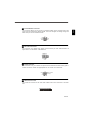
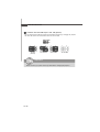
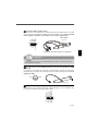
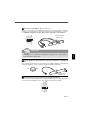
Front USB Connector (Yellow)
This connector, compliant with Intel
®
I/O Connectivity Design Guide, is ideal for con-
necting high-speed USB interface peripherals such as USB HDD, digital cameras, MP3
players, printers, modems and the like.
Note that the pins of VCC and GND must be connected correctly to avoid possible
damage.
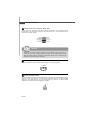
S/PDIF-Out Connector
This connector is used to connect S/PDIF (Sony & Philips Digital Interconnect Format)
interface for digital audio transmission.
Front Panel Audio Connector (Azalia Spec)
This connector allows you to connect the front panel audio and is compliant with Intel
®
Front Panel I/O Connectivity Design Guide.

En-12
MS-7513 Mainboard
15
14
1
2
910
AUD_MIC
AUD_MIC_BIAS
AUD_FPout_R
HP_ON
AUD_FPout_L
AUD_GND
AUD_VCC
AUD_RET_R
Key
AUD_RET_L
13
Important
GND
R
L
2
G
N
D
C
I
N
T
R
U
1
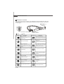
Front Panel Audio Connector (AC97 Spec)
This connector allows you to connect the front panel audio and is compliant with Intel
®
Front Panel I/O Connectivity Design Guide.
If you don’t want to connect to the front audio header, pins 5 & 6, 9 & 10 have
to be jumpered in order to have signal output directed to the rear audio ports.
Otherwise, the Line-Out connector on the back panel will not function.
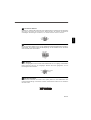
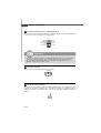
CD-In Connector
This connector is provided for external audio input.
Chassis Intrusion Connector
This connector connects to the chassis intrusion switch cable. If the chassis is opened,
the chassis intrusion mechanism will be activated. The system will record this status and
show a warning message on the screen. To clear the warning, you must enter the BIOS
utility and clear the record.
Seite wird geladen ...
Seite wird geladen ...
Seite wird geladen ...
Seite wird geladen ...
Seite wird geladen ...
Seite wird geladen ...
Seite wird geladen ...
Seite wird geladen ...
Seite wird geladen ...
Seite wird geladen ...
Seite wird geladen ...
Seite wird geladen ...
Seite wird geladen ...
Seite wird geladen ...
Seite wird geladen ...
Seite wird geladen ...
Seite wird geladen ...
Seite wird geladen ...
Seite wird geladen ...
Seite wird geladen ...
Seite wird geladen ...
Seite wird geladen ...
Seite wird geladen ...
Seite wird geladen ...
Seite wird geladen ...
Seite wird geladen ...
Seite wird geladen ...
Seite wird geladen ...
Seite wird geladen ...
Seite wird geladen ...
Seite wird geladen ...
Seite wird geladen ...
Seite wird geladen ...
Seite wird geladen ...
Seite wird geladen ...
Seite wird geladen ...
Seite wird geladen ...
Seite wird geladen ...
Seite wird geladen ...
Seite wird geladen ...
Seite wird geladen ...
Seite wird geladen ...
Seite wird geladen ...
Seite wird geladen ...
Seite wird geladen ...
Seite wird geladen ...
Seite wird geladen ...
Seite wird geladen ...
Seite wird geladen ...
Seite wird geladen ...
Seite wird geladen ...
Seite wird geladen ...
Seite wird geladen ...
Seite wird geladen ...
Seite wird geladen ...
Seite wird geladen ...
Seite wird geladen ...
Seite wird geladen ...
Seite wird geladen ...
Seite wird geladen ...
Seite wird geladen ...
Seite wird geladen ...
Seite wird geladen ...
Seite wird geladen ...
Seite wird geladen ...
Seite wird geladen ...
Seite wird geladen ...
Seite wird geladen ...
Seite wird geladen ...
Seite wird geladen ...
Seite wird geladen ...
Seite wird geladen ...
Seite wird geladen ...
Seite wird geladen ...
Seite wird geladen ...
Seite wird geladen ...
Seite wird geladen ...
Seite wird geladen ...
Seite wird geladen ...
Seite wird geladen ...
Seite wird geladen ...
Seite wird geladen ...
Seite wird geladen ...
Seite wird geladen ...
Seite wird geladen ...
Seite wird geladen ...
Seite wird geladen ...
Seite wird geladen ...
Seite wird geladen ...
Seite wird geladen ...
Seite wird geladen ...
Seite wird geladen ...
Seite wird geladen ...
Seite wird geladen ...
Seite wird geladen ...
Seite wird geladen ...
-
 1
1
-
 2
2
-
 3
3
-
 4
4
-
 5
5
-
 6
6
-
 7
7
-
 8
8
-
 9
9
-
 10
10
-
 11
11
-
 12
12
-
 13
13
-
 14
14
-
 15
15
-
 16
16
-
 17
17
-
 18
18
-
 19
19
-
 20
20
-
 21
21
-
 22
22
-
 23
23
-
 24
24
-
 25
25
-
 26
26
-
 27
27
-
 28
28
-
 29
29
-
 30
30
-
 31
31
-
 32
32
-
 33
33
-
 34
34
-
 35
35
-
 36
36
-
 37
37
-
 38
38
-
 39
39
-
 40
40
-
 41
41
-
 42
42
-
 43
43
-
 44
44
-
 45
45
-
 46
46
-
 47
47
-
 48
48
-
 49
49
-
 50
50
-
 51
51
-
 52
52
-
 53
53
-
 54
54
-
 55
55
-
 56
56
-
 57
57
-
 58
58
-
 59
59
-
 60
60
-
 61
61
-
 62
62
-
 63
63
-
 64
64
-
 65
65
-
 66
66
-
 67
67
-
 68
68
-
 69
69
-
 70
70
-
 71
71
-
 72
72
-
 73
73
-
 74
74
-
 75
75
-
 76
76
-
 77
77
-
 78
78
-
 79
79
-
 80
80
-
 81
81
-
 82
82
-
 83
83
-
 84
84
-
 85
85
-
 86
86
-
 87
87
-
 88
88
-
 89
89
-
 90
90
-
 91
91
-
 92
92
-
 93
93
-
 94
94
-
 95
95
-
 96
96
-
 97
97
-
 98
98
-
 99
99
-
 100
100
-
 101
101
-
 102
102
-
 103
103
-
 104
104
-
 105
105
-
 106
106
-
 107
107
-
 108
108
-
 109
109
-
 110
110
-
 111
111
-
 112
112
-
 113
113
-
 114
114
-
 115
115
-
 116
116


MSI G52-75131X4 Bedienungsanleitung
- Kategorie
- Motherboards
- Typ
- Bedienungsanleitung
- Dieses Handbuch eignet sich auch für
in anderen Sprachen
- English: MSI G52-75131X4 Owner's manual
- français: MSI G52-75131X4 Le manuel du propriétaire
- русский: MSI G52-75131X4 Инструкция по применению
Verwandte Artikel
-
MSI P6N Datenblatt
-
-
-
-
-
MSI G52-73881X4 Bedienungsanleitung
-
-
-
MSI G45Neo3 Serie Bedienungsanleitung
-

