
ESIM120/ESIM320/ESIM320US
USER GUIDEV1.0
RU ES DE
ELDES GATE
CONTROLLER
EN
LT


3EN | LT | RU | ES | DE
INSTALLATION
EN
MONTAVIMAS
LT
RU
INSTALACIÓN
ES
SYSTEMMONTAGE
DE
1 x 1 x 1 x
EN
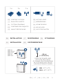
CONTENTS OF PACK
LT
PAKUOTĖS SUDĖTIS
RU
ES
CONTENIDO DEL PAQUETE
DE
INHALT DER PACKUNG
EN
NOT INCLUDED
LT
NEPRIDEDAMA
RU
ES
NO INCLUIDO
DE
NICHT ENTHALTEN
METAL
METALAS
METAL
METALL
>20 cm
(> 7,874 inch.)
FROM THE POWER LINES
NUO ELEKTROS LINIJŲ
DE LAS LÍNEAS ELÉCTRICAS
VON DEN STROMLEITUNGEN
MIN 20
O
C 4
O
F
MAX 55
O
C 131
O
F

4 EN | LT | RU | ES | DE
PIN
ANT
USB
F1
SIM CARD
MO DE M
SIM STAT
NETW
DEF
AC/DC RELAY1 RELAY2COM Z5 Z4 Z3 Z2 Z1
AC/DC RELAY1 RELAY2COM Z5 Z4 Z3 Z2 Z1
ANT
USB
F1
SIM CARD
MO DE M
SIM STAT
NETW
DEF
SMS
SMS
****
+1...5
Number NR4:+441700XXXX110 is set.
1
2
3
5
4

5EN | LT | RU | ES | DE
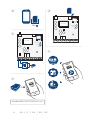
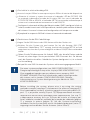
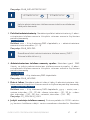
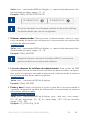
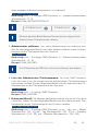
EN
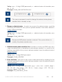
1
Disable PIN code request.
2
Insert the SIM card into the device’s SIM card slot holder.
3
Power up the system and wait unil LED indicator SIM STAT lights up, indicaing
SIM card status. Once the indicator SIM STAT lights OFF, the illuminated
indicator NETW lights up, indicaing that the system has successfully
connected to the GSM/3G network.
4
Set the phone number for Admin 1 (NR 1); set date and ime; change the default
SMS password; you may also change the system’s language. Once the system
is conigured, it is ready to use.
5
Example of the system’s SMS response to the requested command.
LT
1
Išjunkite PIN kodo reikalavimą.
2
Įdėkite SIM kortelę į jai skirtą vietą įrenginyje.
3
Įjunkite sistemą ir laukite, kol SIM STAT indikatorius įsižiebs ir nurodys SIM
kortelės būseną. Kai ik SIM STAT nustos šviesi,šviečianis NETW indikatorius
patvirins, kad sistema yra sėkmingai prijungta prie GSM/3G inklo.
4
Įrašykite administratoriaus telefono numerį (NR 1); nustatykite datą ir laiką;
pakeiskite numatytąjį SMS slaptažodį; esant poreikiui pakeiskite sistemos
kalbą. Atlikus konigūraciją, sistema bus paruošta naudojimui.
5
Sistemos SMS atsakymo į užklausą pavyzdys.
RU
1
PIN .
2
PIN , SIM
.
3
LED SIM
STAT, SIM .
SIM STAT, NETW, ,
GSM/3G .
4
( 1);
; SMS ;
, .
.
5
SMS .

6 EN | LT | RU | ES | DE
ES
1
Deshabilite la solicitud de código PIN.
2
Inserte la tarjeta SIM en la ranura para tarjetas SIM en el interior del disposiivo.
3
Alimente el sistema y espere hasta que el indicador LED de ESTADO SIM
se encienda, indicando el estado de la tarjeta SIM. Una vez el indicador de
ESTADO DE SIM se APAGA, el indicador NETW se enciende, indicando que el
sistema se ha conectado correctamente a la red GSM/3G.
4
Conigure el número de teléfono del Administrador1 (NR1); conigure la fecha y
la hora; cambie la contraseña SMS por defecto; también pude cambiar el idioma
del sistema. Una vez el sistema esté conigurado, está listo para ser usado.
5
Ejemplo de la respuesta SMS del sistema al comando introducido.
DE
1
Deakivieren Sie die PIN-Code Abfrage.
2
Legen Sie die SIM-Karte in den SIM-Kartenschlitz des Gerätes ein.
3
Schalten Sie das System ein und warten Sie, bis die Anzeige SIM STAT
auleuchtet. Sobald diese “OFF” anzeigt, leuchtet die Anzeige NETW auf und
zeigt damit an, dass das System erfolgreich mit dem GSM/3G Netz verbunden
wurde.
4
Geben Sie die Telefonnummer für Admin1 (NR1), das aktuelle Datum und die
Uhrzeit ein, dann legen Sie ein persönliches SMS-Passwort fest. Sie können
auch die Sprache einstellen. Sobald das System koniguriert ist, ist es bereit
zur Verwendung.
5
Beispiel für eine SMS-Antwort des Systems auf einen eingegangenen Befehl.
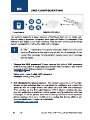
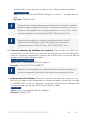
For more system coniguraion, see SMS CONFIGURATION/
Daugiau apie konigūravimą rasite skyriuje SMS KONFIGŪRACIJA/
, SMS
/Para más información sobre la coniguración
del sistema, vea la sección CONFIGURACIÓN SMS /Weitere
Informaionen zur System-Konigurierung im Abschnit SMS-
KONFIGURIERUNG.
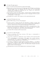
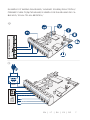
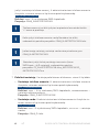
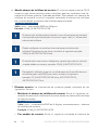
Before installing the system, please wire it up using the wiring
methods example (see page 7) and connect the antenna (see page 3)/
Prieš montuodami sistemą, sujunkite ją pagal schemų pavyzdžius (žr.
pusl. 7) ir prijunkite anteną (žr.pusl. 3)/ ,
(. . 7)
(. . 3)/Antes de instalar el sistema, por
favor, cabléelo usando los métodos del ejemplo de cableado (página
7) y conecte la antena (página 3)/ Vor der System-Installierung
verkabeln Sie das System bite wie im Verkabelungsbeispiel (siehe 7)
angezeigt und verbinden Sie die Antenne (siehe Seite 3).

7EN | LT | RU | ES | DE
GATE AUTOMATION DEVICE
F0 +24vGND
AC/DC
RELAY 1
RELAY 2
COM
Z5
Z4
Z3
Z2
Z1
+
-
GATE
AUTOMATION
DEVICE
AC/DC
RELAY 1
RELAY 2
COM
Z5
Z4
Z3
Z2
Z1
12...24
AC/DC
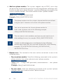
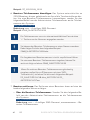
EXAMPLE OF WIRING DIAGRAMS/ JUNGIMO SCHEMŲ PAVYZDŽIAI/
/ EJEMPLO DE DIAGRAMAS DE CA
BLEADO/ SCHALTPLANBEISPIEL/
1
2

8 EN | LT | RU | ES | DE
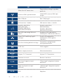
EN LT RU ES DE
Main Unit & Connectors
Pagrindinių mazgų ir gnybtų
paskiris
Unidad Principal &
Conectores
Haupteinheit & An-
schlüsse
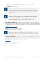
Antenna SMA type connector
GSM/GPRS antenos SMA ipo
jungis
SMA
GSM/GPRS
Conector de antena ipo
SMA
SMA-Antennenanschluss
Mini USB port Mini USB jungis Mini USB Puerto miniUSB Mini USB-Port
SIM card slot / holder SIM kortelės lizdas ir laikiklis
/ SIM
Ranura/soporte para
tarjeta SIM
SIM-Kartenschlitz
ESIM120 -850/900/
1800/1900 MHz;
ESIM320- 850/900/
1800/1900/2100 MHz
ESIM120 -850/900/
1800/1900 MHz;
ESIM320- 850/900/
1800/1900/2100 MHz
ESIM120 -850/900/
1800/1900 ;
ESIM320- 850/900/
1800/1900/2100
ESIM120 -850/900/
1800/1900 MHz;
ESIM320- 850/900/
1800/1900/2100 MHz
ESIM120 -850/900/
1800/1900 MHz;
ESIM320- 850/900/
1800/1900/2100 MHz
Red LED, indicaing SIM card
status
Raudonas LED indikatorius,
indikuojanis SIM kortelės būseną
LED
SIM
LED rojo, indica el estado
de la tarjeta SIM
Rote LED, zeigt den SIM-
Kartenstatus an
Green LED, indicaing signal
strength
Žalias LED indikatorius,
indikuojanis GSM signalo
siprumą
LED
LED verde, indica el nivel
de señal
Grüne LED, zeigt die
Signalstärke an
Pins for restoring default seings
Gamyklinės konigūracijos
atstatymo kontaktai
Pins para restablecer los
ajustes por defecto
Pins für die
Wiederherstellung der
Standardeinstellung
0.5A fuse 0.5A saugiklis 0.5A Fusible 0.5A 0.5A Sicherung
AC/DC Power supply terminals Maiinimo kontaktai
Terminales de la fuente de
alimentación
Stromanschluss
RELAY
12
Output C1-C2 terminal Išėjimo C1-C2 kontaktas 1-C2 Terminal de salida C1-C2 C1-C2 Ausgangsanschluss
COM Common terminal Bendras kontaktas Terminal común Masseanschluss
Z1/Z3
Low-level (negaive input
terminal)
„Žemo lygio“ (neigiamas) įėjimo
kontaktas
„“
()
Nivel bajo (entrada de
terminal negaiva)
Low Level
Eingangsanschluss
(Eingangs-Minuspol)
Z2
High-level (posive input
terminal)
„Aukšto lygio“ (teigiamas) įėjimo
kontaktas
„“
()
Nivel alto (terminal de
entrada posiivo)
High Level
Eingangsanschluss
(Eingangs-Pluspol)
Z4Z5 N/A Negalima No permiido Nicht erlaubt

9EN | LT | RU | ES | DE
EN LT RU ES DE
Main Unit & Connectors
Pagrindinių mazgų ir gnybtų
paskiris
Unidad Principal &
Conectores
Haupteinheit & An-
schlüsse
Antenna SMA type connector
GSM/GPRS antenos SMA ipo
jungis
SMA
GSM/GPRS
Conector de antena ipo
SMA
SMA-Antennenanschluss
Mini USB port Mini USB jungis Mini USB Puerto miniUSB Mini USB-Port
SIM card slot / holder SIM kortelės lizdas ir laikiklis
/ SIM
Ranura/soporte para
tarjeta SIM
SIM-Kartenschlitz
ESIM120 -850/900/
1800/1900 MHz;
ESIM320- 850/900/
1800/1900/2100 MHz
ESIM120 -850/900/
1800/1900 MHz;
ESIM320- 850/900/
1800/1900/2100 MHz
ESIM120 -850/900/
1800/1900 ;
ESIM320- 850/900/
1800/1900/2100
ESIM120 -850/900/
1800/1900 MHz;
ESIM320- 850/900/
1800/1900/2100 MHz
ESIM120 -850/900/
1800/1900 MHz;
ESIM320- 850/900/
1800/1900/2100 MHz
Red LED, indicaing SIM card
status
Raudonas LED indikatorius,
indikuojanis SIM kortelės būseną
LED
SIM
LED rojo, indica el estado
de la tarjeta SIM
Rote LED, zeigt den SIM-
Kartenstatus an
Green LED, indicaing signal
strength
Žalias LED indikatorius,
indikuojanis GSM signalo
siprumą
LED
LED verde, indica el nivel
de señal
Grüne LED, zeigt die
Signalstärke an
Pins for restoring default seings
Gamyklinės konigūracijos
atstatymo kontaktai
Pins para restablecer los
ajustes por defecto
Pins für die
Wiederherstellung der
Standardeinstellung
0.5A fuse 0.5A saugiklis 0.5A Fusible 0.5A 0.5A Sicherung
AC/DC Power supply terminals Maiinimo kontaktai
Terminales de la fuente de
alimentación
Stromanschluss
RELAY
12
Output C1-C2 terminal Išėjimo C1-C2 kontaktas 1-C2 Terminal de salida C1-C2 C1-C2 Ausgangsanschluss
COM Common terminal Bendras kontaktas Terminal común Masseanschluss
Z1/Z3
Low-level (negaive input
terminal)
„Žemo lygio“ (neigiamas) įėjimo
kontaktas
„“
()
Nivel bajo (entrada de
terminal negaiva)
Low Level
Eingangsanschluss
(Eingangs-Minuspol)
Z2
High-level (posive input
terminal)
„Aukšto lygio“ (teigiamas) įėjimo
kontaktas
„“
()
Nivel alto (terminal de
entrada posiivo)
High Level
Eingangsanschluss
(Eingangs-Pluspol)
Z4Z5 N/A Negalima No permiido Nicht erlaubt

10 EN | LT | RU | ES | DE
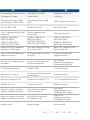
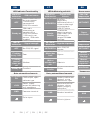
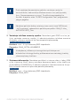
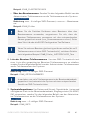
LED Indicator Funcionality
SIM STAT
indicaion
SIM card status
OFF
No mains power
/ successfully
connected to
GSM/3G network
Steady on
SIM card is
atemping to
connect to the
GSM/3G network
/ SIM card is not
present / PIN code
enabled
NETW
indicaion
Signal strength
OFF No GSM/3G signal
Flashing
every 1 sec.
Poor
Flashing
several
imes per
sec.
Medium
Steady on Excellent
Gate automaion elements
FO
Fault output; open
collector type
24V
Power supply
output for powering
aux. equipment
GND Common terminal
Pulse input
LED Indikatorių paskiris
SIM STAT
indikatorius
SIM kortelės
būsena
NEŠVIEČIA
Neveikia
pagrindinis
maiinimo šalinis /
sistema sėkmingai
prisijungė prie
GSM/3G inklo
Nuolat
šviečia
Sistema dar
neprisijungė prie
GSM inklo / nėra
SIM kortelės /
įjungta PIN kodo
apsauga
NETW in-
dikatorius
Signalo siprumas
NEŠVIEČIA
Nėra GSM/3G
signalo
Mirksi kas
1 sek.
Silpnas
Mirksi
keliskart per
sek.
Viduinis
Nuolat
šviečia
Puikus
Vartų automaikos elementai
FO
Gedimų indikavimo
išėjimas; atviro
kolektoriaus ipas
24V
Maiinimo šalinio
išėjimas, skirtas
papild. įrenginių
maiinimui
GND Bendras kontaktas
Pulsinis įėjimas
LED
SIM STAT
SIM
/
GSM/3G
SIM
GSM/3G /
SIM / SIM
PIN
NETW
GSM/3G
.
FO
;
24V
.
GND
EN LT RU

11EN | LT | RU | ES | DE
LED
SIM STAT
SIM
/
GSM/3G
SIM
GSM/3G /
SIM / SIM
PIN
NETW
GSM/3G
.
FO
;
24V
.
GND
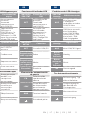
Funciones del indicador LED
Indicación
SIM STAT
Estado de tarjeta
SIM
OFF
Sin alimentación
principal /
Conectado
correctamente a
red GSM/3G
Encendido
La tarjeta SIM
está tratando
de conectar a la
red GSM/3G /
No hay tarjeta
SIM / Código PIN
habilitado
Indicación
NETW
Cobertura
OFF Sin señal GSM/3G
Parpadeando
cada segundo
Pobre
Parpadeando
varias veces
por segundo
Media
Encendido Excelente
Elementos de automaización
de puerta
FO
Fallo de salida;
ipo de colector
abierto
24V
Salida de fuente
de alimentación
para alimentar
equipos auxiliares
GND Terminal común
Entrada de pulso
Funkionen der LED-Anzeigen
SIM STAT
Anzeige
SIM-Kartenstatus
AUS
Kein Netzstrom
/ erfolgreich
verbunden mit dem
GSM/3G Netz
An
SIM-Karte versucht,
eine Verbinding
zum GSM/3G Netz
herzustellen / SIM-
Karte fehlt / PIN-
Code freigegeben
NETW
Anzeige
Signalstärke
AUS Kein GSM/3G Signal
Blinkt
1x pro
Sekunde
Niedrig
Blinkt
mehrmals
pro
Sekunde
Mitel
An Hervorragend
Tor-Automaionselemente
FO
Fehlerausgang; Typ
ofener Kollektor
24V
Stromausgang für
den Betrieb von
Zusatzgeräten
GND Masseanschluss
Impulseingang
ES DE

ELDES GATE CONTROLLER ESIM120/ESIM32012 EN
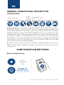
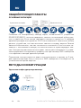
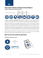
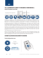
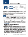
GENERAL OPERATIONAL DESCRIPTION
MAIN FEATURES
Output control by
Input
noiica-
ion by
Intended
for
Extras
iOS
SMS
2000 1000
When a phone call is made to the phone number of the SIM card inserted in
ESIM120/ESIM320, the system will verify if the caller’s phone number exists
in the device database. If the caller is one of the 5 administrators or the phone
number belongs to one of the 2000 database users, the system will reject
the phone call, thus making the phone call free of charge, and open the gate.
If the phone number is not recognized, the system will reject the phone call
and ignore it. The gate controller can also control your gate automaically
in accordance with the scheduled ime or by sending an SMS text message
from the administrator’s phone number.
By connecing a sensor to one of the 3 inputs, the administrators can receive
SMS text messages regarding the gates that failed to close during the set
ime period.
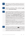
CONFIGURATION METHODS
Remote coniguraion by
ELDES
Coniguraion
Tool
SMS
EN

ELDES GATE CONTROLLER ESIM120/ESIM320
EN 13
Before staring to use ELDES Configuration Tool sotware, please
read the user guide provided in the sotware’s HELP secion.
ELDES Configuration Tool sotware is secured with SMS
password. The default SMS password is 0000 (see SMS
CONFIGURATION).
• ESIM120 is NOT compaible with pure 3G SIM cards. Only 2G SIM cards
and 3G SIM cards with 2G/GSM proile enabled are supported. Meanwhile,
ESIM320 is compaible with any SIM card and supports both 2G and 3G
connecions. For more details, please contact your operator.
• We also recommend you to disable call forwarding, voice mail/text mes-
sage reports on missed/busy calls and similar services that might cause
incorrect system operaion. Please contact your operator for more details
on these services and how to disable them.
• For maximum system reliability we recommend you do NOT use a Pay As
You Go SIM card. Otherwise, in the event of insuicient credit balance on
the SIM card, the system would fail to make a phone call or send SMS text
messages.
• We advise you to choose the same GSM provider for your system as for
your mobile phone. This will ensure the fastest, most reliable SMS text mes-
sage delivery service and phone call connecion.
• Even though the installaion process of ESIM120/ESIM320 is not too com-
plicated, we sill recommend to perform it by a person with basic knowledge
in electrical engineering and electronics to avoid any system damage.
• Please use the 10-24V 50Hz/ 60Hz ~200mA AC or 10-24V 200mA DC
power supply unit that meets the EN 60950-1 standard. Any addiional de-
vice you connect to the system, such as a computer, must also be powered
by an EN 60950-1 approved supply. When connecing the power supply to
the system, switching the polarity terminal places does not have any afect.

ELDES GATE CONTROLLER ESIM120/ESIM32014 EN
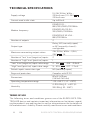
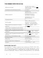
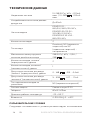
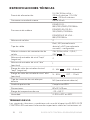
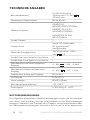
TECHNICAL SPECIFICATIONS
Supply voltage
10-24V 50Hz/ 60Hz ~
200mA max / 10-24V
200mA max
Current used in idle state Up to 50mA
Modem frequency
ESIM120 2G -
850/900/1800/1900MHz
ESIM320 3G/2G EU -
900/1800/2100MHz
ESIM320US 3G USA -
850/1900MHz
Number of outputs 2
Output type
Relay; NO (normally-open)
or NC (normally-closed) -
conigurable
Maximum commuing output values
24V 50Hz/ 60Hz ~ 0,5A /
24V 1A
Number of “low” level (negaive) inputs 2
Number of “high” level (posiive) inputs 1
“Low” level (negaive) input value range 0... 16V -0.8... -0.4mA
“High” level (posiive) input value range 5... 50V 0.17 ... 1.7mA
Default inputs connecion type NO (normally-open)
Degree of protecion Complies with IP 20
Dimensions
87x107x29mm
(3.43x4.21x1.14in)
Operaing temperature range -20…+55 °C (-4... +131°F)
Humidity
0-90% RH @ 0... +40°C (0-
90% RH @ 32... 104°F)
TERMS OF USE
The following terms and condiions govern use of the ELDES GATE CON-
TROLLER device and contains important informaion on limitaions regard-
ing the product’s use and funcion, as well as informaion on the limitaions of
the manufacturer’s liability. Please carefully read these terms and condiions.

ELDES GATE CONTROLLER ESIM120/ESIM320
EN 15
For more informaion on your product, please visit eldesalarms.com
TECHNICAL SUPPORT
In order to ensure coninuous and proper operaion of the ELDES Gate Con-
troller device and uninterrupted service, it is the responsibility of the User to
make sure that: (i) the product is properly installed, and (ii) there is constant
electrical supply. If you experience diiculty during the installaion or sub-
sequent use of the system, you may contact “ELDES, UAB” distributor or
dealer in your country/region. For more informaion, visit eldesalarms.com
WARRANTY PROCEDURES
Warranty and out of warranty service should be obtained by contacing the
system integrator/dealer/retailer/e-tailer or distributor where the customer
purchased the product. When requesing for service, the proof of purchase
and the product serial number must be provided. The return of the defec-
ive product should be strictly through the original route of purchase, and
the customers shall pack the product appropriately to prevent the returned
product from sufering in the transportaion.
LIMITED LIABILITY
The buyer must agree that the system will reduce the risk thet, burglary or
other dangers but does not provide guarantee against such events. “ELDES,
UAB” will not assume any responsibility regarding personal or property, or
revenue loss while using the system.“ELDES, UAB” shall also assume no lia-
bility due to direct or indirect damage or loss, as well as unreceived income
when using the system, including cases, when the damages arise due to the
above menioned risks, when due to breakdown or malfuncion the user is
not informed in a imely manner about a risk which has arisen. In any case,
the liability of “ELDES, UAB”, as much as it is allowed by the laws in force,
shall not exceed the price of acquisiion of the product.
MANUFACTURER WARRANTY
ELDES provides a limited warranty for its products only to the person or
enity that originally purchased the product from ELDES or its authorized
distributor or retailer and only in case of defecive workmanship and mate-
rials under normal use of the system for a period of twenty four (24) months
from the date of shipment by the “ELDES, UAB” (Warranty Period). Warran-
ty obligaions do not cover expandable materials (power elements and/or
bateries), holders and enclosures. The warranty remains valid only if the
system is used as intended, following all guidelines outlined in this manual
and in accordance with the operaing condiions speciied. The warranty is

ELDES GATE CONTROLLER ESIM120/ESIM32016 EN
void if the system has been exposed to mechanical impact, chemicals, high
humidity, luids, corrosive and hazardous environments or force majeure
factors. If a hardware defect arises and a valid claim is received within the
Warranty Period, at its own discreion, “ELDES, UAB” will either (a) repair a
hardware defect at no charge, using new or refurbished replacement parts,
or (b) exchange the product with a product that is new or which has been
manufactured from new or serviceable used parts and is at least funcion-
ally equivalent to the original product, or (c) refund the purchase price of
the product.
CONSUMER PROTECTION LAWS
For consumers who are covered by consumer protecion laws or regulaions
in their country of purchase or, if diferent, their country of residence, the
beneits conferred by this warranty are in addiion to all rights and remedies
conveyed by such consumer protecion laws and regulaions. This warranty
grants upon you speciic legal rights, and you may also have other rights
that vary by country, state or province.
SAFETY INSTRUCTIONS
Please read and follow these safety guidelines to safeguard yourself and
others:
• DO NOT use the system where it can cause potenial danger and interfere
with other devices – such as medical devices
• DO NOT use the system in hazardous environment
• DO NOT expose the system to high humidity, chemical environment or
mechanical impact
• NEVER install or carry out maintenance during stormy weather.
• DO NOT atempt to repair the system yourself - any repairs must be car-
ried out by fully qualiied personnel only


ELDES GATE CONTROLLER ESIM120/ESIM32018 LT
LT
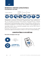
BENDRAS VEIKIMO APRAŠYMAS
PAGRINDINĖS SAVYBĖS
Išėjimo valdymas
Įėjimo
praneši-
mai
Paskiris Priedai
iOS
SMS
2000 1000
Paskambinus sistemos ESIM120/ESIM320 telefono numeriu, ši paikrina, ar
skambinanis vartotojas yra įtrauktas į duomenų bazę. Jeigu skambina vie-
nas iš 5 vartotojų, kurių numeris buvo įrašytas, arba jeigu numeris įtrauktas
į 2000 vartotojų duomenų bazę, sistema atmes skambuį ir aidarys vartus.
Skambinant iš neįrašyto telefono numerio, sistema jį atmes bei ignoruos to-
limesnius skambučius iš šio numerio. Vartų valdiklis suteikia galimybę au-
tomaiškai valdyi vartus tvarkaraščio pagalba arba siunčiant SMS žinutę iš
administratoriaus numerio.
Prijungus vartų juiklį prie vieno iš 3 įėjimų, administratorius gali gaui SMS
žinutes dėl nepavykusio bandymo aidaryi vartus per nurodytą laikotarpį.
KONFIGŪRACIJOS BŪDAI
Nuotolinis konigūravimas per
ELDES
Coniguraion
Tool
SMS

ELDES GATE CONTROLLER ESIM120/ESIM320
LT 19
Prieš pradedant naudoi ELDES Configuration Tool programinę
įrangą, prašom perskaityi instrukciją, kurią rasite programinės
įrangos HELP skyriuje.
Prieiga prie sistemos konigūracijos, naudojant „ELDES
Coniguraion Tool“ programinę įrangą, yra apsaugota SMS
slaptažodžiu. Gamyklinis SMS slaptažodis yra 0000 (žr.skyrių
SMS KONFIGŪRACIJA).
• ESIM120 neveikia naudojant 3G SIM korteles. Tik 2G SIM kortelės ir 3G SIM
kortelės su aktyvuotu 2G proiliu yra palaikomos. Tuo tarpu ESIM320 veikia
naudojant visų ipų korteles, palaiko abu 2G ir 3G ryšio metodus. Išsames-
nės informacijos teiraukitės savo paslaugų operatoriaus.
• Įsiikinkite, kad papildomos paslaugos, kaip balso paštas, skambučių pe-
radresavimas ir ataskaitos apie praleistus/, užimtus skambučius, yra
išjungtos. Išsamiau apie tai, kaip išjungi šias paslaugas, teiraukitės savo
paslaugų operatoriaus.
• Tam, kad sistema veiktų opimaliai, patariame nenaudoi išanksinio pa-
pildymo SIM kortelių. Priešingu atveju, esant nepakankamam SIM kortelės
sąskaitos likučiui, sistema negalės paskambini vartotojui arba išsiųsi SMS
žinutės.
• Rekomenduojame naudoi tą paį GSM ryšio operatorių kaip ir pagrindinis
sistemos administratorius. Tai užikrins paikimą bei greičiausią SMS žinu-
tės pristatymą bei skambučio sujungimą.
• Nors sistemos ESIM120/ESIM320 montavimas ir nėra sudėingas, tačiau
siekdami išvengi galimų sistemos gedimų, tai atliki rekomenduojame ik
asmenims, turiniems minimalias elektrotechnikos ar elektronikos žinias.
• Sistema turi būi maiinama iš 10-24V 50Hz/60Hz ~200mA kintamos sro-
vės arba 10-24V 200mA nuolainės srovės maiinimo šalinio, kuris
turi aiiki LST EN 60950-1 standarto reikalavimus. Kiekvienas prie siste-
mos ESIM120 prijungtas susietasis įrenginys (kompiuteris, juikliai, relės ir
pan.) turi aiiki LST EN 60950-1 standarto reikalavimus. Jungiant sistemą
prie maiinimo gnybtų, polių sukeiimas neturi reikšmės.

ELDES GATE CONTROLLER ESIM120/ESIM32020 LT
TECHNINĖ SPECIFIKACIJA
Maiinimo įtampa
10-24V 50Hz/ 60Hz ~
200mA maks. / 10-24V
200mA maks.
Vartojama srovė budėjimo režime Iki 50mA
Modemo dažnis
ESIM120 2G -
850/900/1800/1900MHz
ESIM320 3G/2G EU -
900/1800/2100MHz
ESIM320US 3G USA -
850/1900MHz
Išėjimų skaičius 2
Išėjimų ipas
Relinis; NO (normaliai
atviras) ar NC (normaliai
uždaras) - konigūruojama
Maksimalios komutuojamos išėjimų
reikšmės
24V 50Hz/ 60Hz ~ 0,5A /
24V 1A
„Žemo lygio“ (neigiamų) įėjimų skaičius 2
„Aukšto lygio“ (teigiamų) įėjimų skaičius 1
„Žemo lygio“ (neigiamų) įėjimo leisinos
reikšmės
0... 16V -0.8... -0.4mA
„Aukšto lygio“ (teigiamų) įėjimo leisinos
reikšmės
5... 50V 0.17 .... 1.7mA
Numatytasis įėjimų jungimo ipas NO (normaliai atviras)
Apsaugos klasė Aiinka IP 20
Matmenys 87x107x29mm
Darbo temperatūros diapazonas -20…+55 °C
Drėgmė 0-90% RH @ 0... +40°C
NAUDOJIMO SĄLYGOS
Šios nuostatos ir sąlygos reglamentuoja naudojimąsi ELDES GATE CON-
TROLLER įrenginiu ir pateikia svarbią informaciją apie apribojimus, susiju-
sius su gaminio naudojimu ir funkcionavimu, taip pat informaciją apie ga-
mintojo atsakomybės ribojimą. Prašom aidžiai perskaityi šias nuostatas
Seite wird geladen ...
Seite wird geladen ...
Seite wird geladen ...
Seite wird geladen ...
Seite wird geladen ...
Seite wird geladen ...
Seite wird geladen ...
Seite wird geladen ...
Seite wird geladen ...
Seite wird geladen ...
Seite wird geladen ...
Seite wird geladen ...
Seite wird geladen ...
Seite wird geladen ...
Seite wird geladen ...
Seite wird geladen ...
Seite wird geladen ...
Seite wird geladen ...
Seite wird geladen ...
Seite wird geladen ...
Seite wird geladen ...
Seite wird geladen ...
Seite wird geladen ...
Seite wird geladen ...
Seite wird geladen ...
Seite wird geladen ...
Seite wird geladen ...
Seite wird geladen ...
Seite wird geladen ...
Seite wird geladen ...
Seite wird geladen ...
Seite wird geladen ...
Seite wird geladen ...
Seite wird geladen ...
Seite wird geladen ...
Seite wird geladen ...
Seite wird geladen ...
Seite wird geladen ...
Seite wird geladen ...
Seite wird geladen ...
Seite wird geladen ...
Seite wird geladen ...
Seite wird geladen ...
Seite wird geladen ...
-
 1
1
-
 2
2
-
 3
3
-
 4
4
-
 5
5
-
 6
6
-
 7
7
-
 8
8
-
 9
9
-
 10
10
-
 11
11
-
 12
12
-
 13
13
-
 14
14
-
 15
15
-
 16
16
-
 17
17
-
 18
18
-
 19
19
-
 20
20
-
 21
21
-
 22
22
-
 23
23
-
 24
24
-
 25
25
-
 26
26
-
 27
27
-
 28
28
-
 29
29
-
 30
30
-
 31
31
-
 32
32
-
 33
33
-
 34
34
-
 35
35
-
 36
36
-
 37
37
-
 38
38
-
 39
39
-
 40
40
-
 41
41
-
 42
42
-
 43
43
-
 44
44
-
 45
45
-
 46
46
-
 47
47
-
 48
48
-
 49
49
-
 50
50
-
 51
51
-
 52
52
-
 53
53
-
 54
54
-
 55
55
-
 56
56
-
 57
57
-
 58
58
-
 59
59
-
 60
60
-
 61
61
-
 62
62
-
 63
63
-
 64
64


