
OPERATING INSTRUCTIONS / BEDIENUNGSANLEITUNG
AAS-100 A
GSM AMOK-ALARMSYSTEM
- ENGLISH
- DEUTSCH

GSM AMOK-ALARM SYSTEMS AAS-200 A
2
ALARM GSM MODUL
UNIVERSAL PER PC PROGRAMMIERBAR
Beschreibung
Das Amokalarm-System AAS-200 A bietet die Möglichkeit,
durch einen Anruf von einem autorisierten Handy der Lehre-
rin oder des Lehrers automatisch einen Kontakt im Alarmie-
rungssystem zu aktivieren. Dieser Kontakt schaltet je nach
Anforderung und Gegebenheit eine automatische Lautspre-
cherdurchsage oder einen entsprechenden Signalton. Wei-
tere Alarmszenarien (z.B. Anruf bei einer Notruf-Leitstelle)
lassen sich ebenfalls gestalten.
TECHNISCHE MERKMALE:
• Frequenzbereich 900/1800/1900MHz
• Betriebsspannung 12V DC, max. Stromaufnahme 1A, im
Ruhemodus 5mA
• Temperaturbereich 0 bis 40 Grad C
• Außenmasse: 96mm x 63mm x 28mm
• 4 Eingänge gesteuert mit Spannungen zwischen 0 und
15V (0-3V Low Signal / 7-12V High Signal)
• 4 Ausgänge NO/NC potenzialfrei 0,5A/130V AC oder
1A/30V DC
• Relais mit montostabiler (Zeitintervall) und bistabiler (Ein/
Aus) Schaltung
• Steuerung per SMS oder CLIP (Anruf) von bis zu 256 Te-
lefonnummern
• Benachrichtigung per SMS oder CLIP auf 6 Telefonnum-
mer TAMPER Schaltung zum Signalisieren des Gehäu-
seöffnens
• Testanruf/SMS im Zeitintervall einstellbar
• Begrenzung der SMS Nachrichten pro 24h
• Zum Programmieren wird ein gewöhnliches USB mini
Kabel benötigt
• Mit jeder normalen SIM Karte verwendbar (PIN 1234 oder
abgeschaltet)
• Ein Netzteil kann optional erworben werden, welches an
+ / - angeschloßen wird
FUNKTIONSWEISE
Die Programmiersoftware bestimmt die Aktionen, welche bei
Steuerung der Eingänge und Ausgänge ausgeführt werden
sollen. Die Software kann unter folgendem Link herunterge-
laden werden:
www.rcs-audio.com/software/gsm2.zip
ALARM GSM MODUL
UNIVERSAL PER PC PROGRAMMIERBAR
Description
The amok alarm system AAS-100 A is activated by an inco-
ming call from an authorized cell phone, for example owned
by a teacher at a school. In a standard setup the incoming
call triggers a pre-recorded, automatic announcement via
the paging system. Additional functions, for example an au-
tomatic call to an emergency response centre, can be imple-
mented as well.
TECHNICAL FEATURES:
• Frequency range 900/1800 / 1900MHz
• Operating voltage 12V DC, max. Current consumption
1A, in sleep mode 5mA
• Temperature range 0 to 40 degrees C.
• External dimensions: 96mm x 63mm x 28mm
• 4 inputs controlled with voltages between 0 and 15V (0-
3V low signal / 7-12V high signal)
• 4 outputs NO/NC potential-free 0.5A/130V AC or 1A/30V
DC
• Relays with montostable (time interval) and bistable (on/
off) switching
• Control via SMS or CLIP (call) of up to 256 phone numbers
• Notification by SMS or CLIP on 6 telephone numbers
TAMPER circuit to signal the opening of the housing
• Test call / SMS adjustable in time interval
• Limitation of SMS messages per 24 hours
• A normal USB mini cable is required for programming
• Can be used with any normal SIM card (PIN 1234 or swit-
ched off)
• A power supply can be purchased optionally, which is
connected to + / -
FUNCTIONALITY
The programming software determines the actions that
should be carried out when the inputs and outputs are con-
trolled. The software can be downloaded from the following
link:
www.rcs-audio.com/software/gsm2.zip
Electromagnetic compatibility and low-voltage guidelines: RCS leaves all devices and products, which are subject to the CE guidelines by certified test laboratories test.
By the fact it is guaranteed that you may sell our devices in Germany and in the European Union domestic market without additional checks.
Elektromagnetische Verträglichkeit und Niederspannungsrichtlinien: RCS läßt alle Geräte und Produkte, die den CE-Richtlinien unterliegen durch zertifizierte Prüflabors
testen. Dadurch ist sichergestellt, dass Sie unsere Geräte in Deutschland und im EU-Binnenmarkt ohne zusätzliche Prüfungen verkaufen dürfen.

AAS-200 A AMOK-ALARMSYSTEM GSM
3
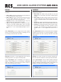
EINGÄNGE
Für jeden der 4 Eingänge (im Bild Inputs 1-4) bestimmt man
Merkmale für das Auslösesignal: LOW = L oder HIGH = H.
LOW bedeutet, daß eine Spannung zwischen 0,2 und 5V
liegt (Switch over voltage level = 5,00) und HIGH entspre-
chend zwischen 5V und 14,5V anliegt.
Beispiel: man schleift +12V von der Spannungsversorgung
über einen Schalter und vom Schalter auf Eingang 1 beim
Schalten (z.B. durch einen Alarm) liegt dann +12V (= HIGH)
am Eingang 1 und das Modul kann eine vorher eingespei-
cherte Aktion ausführen.
INPUTS
For each of the 4 inputs (inputs 1-4 in the figure) characteri-
stics for the trigger signal are determined:
LOW = L or HIGH = H. LOW means that a voltage is between
0.2 and 5V (switch over voltage level = 5.00 ) and HIGH bet-
ween 5V and 14.5V.
Example: you drag + 12V from the power supply via a switch
and from the switch to input 1 when switching (e.g. by an
alarm) there is + 12V (= HIGH) at input 1 and the module can
perform a previously saved action.
Im Bild sehen Sie die Einstellungen für die 4 Eingänge. Zu-
sätzlich gibt man hier noch den optionalen SMS Text ein.
SMS text on input set ON = SMS Text sobald ein Signal am
Eingang anliegt und SMS text input set OFF = ein Text, wenn
der Eingang wieder zurück auf 0 geht.
The picture shows the settings for the 4 inputs. In addition,
you can enter the optional SMS text here. SMS text on input
set ON = SMS text as soon as a signal is present at the input
and SMS text input set OFF = a text when the input goes
back to 0.
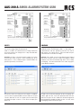
Antenne SMA
SIM Card
TAMPER
Tamper-
anschluss
LED Anzeige
PC Anschluss
JP Jumper
Jumper für NC/NO Betriebsart
antenna SMA
connector
SIM card slot
TAMPER switch
TAMPER
connectors
LED indicator
PC cable socket
JP jumpers
output mode jumpers (shown configured NO)

GSM AMOK-ALARM SYSTEMS AAS-200 A
4
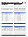
AUSGÄNGE
Das Modul hat 4 Ausgänge. Die Ausgänge können folgend
programmiert werden :
1. Monostabil: das Relais wird geschaltet für die Zeit
00:00:10 also 10 Sekunden (Zeit kann hierbeifestgelegt
werden.
2. Monostabil: das Relais wird geschaltet für die Zeit wel-
che in der SMS stehen muß: SMS Text inder Form „OUT1
2.30.00“ schaltet den Relais 1 für 2 Stunden und 30 Mi-
nuten.
3. Bistabil: das Relais wird abwechselnd geschaltet (On /
Off). Die SMS lautet OUT1 Y für ON und OUT1 N für OFF
4. Beliebig: die Schaltung erfolgt entsprechend den Vorga-
ben in der SMS. Beispiel sms: OUT1 2.30 OUT2 Y. Schal-
ter Relais 1 für 2 Stunden und 30 Minuten und Relais 2
Bistabil auf On. Y = Yes, möglich wäre noch N= No =>
Off.
Unter Output Name können Sie einen Namen der Ausgänge
vergeben und statt OUT1 z.B. Heizung eingeben. Dement-
sprechend kann man dann „Heizung“ statt OUT in den SMS
verwenden.
OUTPUTS
The module has 4 outputs. The outputs can be programmed
as follows:
1. Monostable: The relay is switched for the time 00:00:10,
i.e. 10 seconds (time can be set here.
2. Monostable: the relay is switched for the time that must
be in the SMS: SMS text in the form „OUT1 2.30.00“
switches relay 1 for 2 hours and 30 minutes.
3. Bistable: the relay is switched alternately (On / Off). The
SMS is OUT1 Y for ON and OUT1 N for OFF
4. Any: The switching takes place according to the speci-
fications in the SMS. Example SMS: OUT1 2.30 OUT2
Y. Switch relay 1 for 2 hours and 30 minutes and relay 2
bistable on. Y = Yes, it would still be possible N = No =>
Off.
Under Output Name you can assign a name for the outputs
and e.g. instead of OUT1 Enter heating. Accordingly, you can
use „heating“ instead of OUT in the SMS.
Wichtig: nur Punkt 1 kann per CLIP (Anruf) ausgelöst wer-
den, die restlichen Funktionen sind nur per SMS erreichbar.
Unter Inputs-Outputs können direkte Weiterschaltungen
der Inputs auf Outputs auslösen d.h. bei bestimmten Ein-
gängen zusätzlich die Ausgänge schalten z.B. bei Alarm auf
Eingang x die Außensirene auf Relais y einschalten
Important: only point 1 can be triggered by CLIP (call), the
remaining functions can only be reached by SMS.
Under Input-Outputs direct forwarding of the inputs to
outputs can be triggered i.e. for certain inputs, additionally
switch the outputs e.g. in the event of an alarm on input x,
switch on the external siren on relay y

AAS-200 A AMOK-ALARMSYSTEM GSM
5
BENUTZER (PHONES-OUTPUTS):
Nun springen wir auf Phones-Outputs. Hier können 256
Benutzer in der Form +49xxxx... angelegt werden. Jedem
Benutzer kann bei CLIP (Anruf) eine oder mehrere Schal-
tungen der Relais und SMS Funktionalität freigegeben wer-
den (Häckchen entsprechend setzen).
Zusätzlich können Sie bestimmen, ob die SMS Funktiona-
lität von jeder Nummer (received from any...) oder nur aus
der Liste akzeptiert werden (received from a selected phone
number). CLIP (Anruf) kann nur von der Nummer aus der Li-
ste akzeptiert werden (Schaltung von einer beliebigen Num-
mer ist nicht möglich)
USERS (PHONES-OUTPUTS):
Now we jump to Phones-Outputs. 256 users in the form +
49xxxx ... can be created here. With CLIP (call), each user
can be enabled one or more circuits of the relays and SMS
functionality (tick accordingly).
In addition, you can determine whether the SMS function-
ality is accepted by each number (received from any ...) or
only from the list (received from a selected phone number).
CLIP (call) can only be accepted from the number in the list
(switching from any number is not possible)
BENACHRICHTIGUNGEN (INPUTS-PHONES):
Kehren wir nun zurück zu Inputs-Phones. Hier erscheinen
jetzt die ersten 6x Benutzer aus OutputsPhones. Das Modul
kann nämlich auf max. 6 Nummern Benachrichtigung sen-
den.
NOTIFICATIONS (INPUTS-PHONES):
Now let‘s go back to Input Phones. The first 6x users from
OutputsPhones now appear here. The module can namely
max. Send 6 numbers notification.

GSM AMOK-ALARM SYSTEMS AAS-200 A
6
Die Benachrichtigungen können Sie selbst bestimmen. Set-
zen Sie ein Häkchen bei den entsprechenden Funktionen.
SMS on IN1 set ON bedeutet, daß Sie eine SMS bekommen
mit dem Text welcher bereits unter Punkt Inputs eingegeben
worden ist. Wählen Sie nur CLIP, ruft das Modul lediglich die
Nummer an. Es geht auch SMS und CLIP zusammen.
Bei CLIP (Anruf) wird bei nicht erreichen/besetzt 3x wieder-
holt, jedoch zuerst weitere Nummern aus der Tabelle angeru-
fen (erst nach dem die Liste abgearbeitet ist, wird die Wahl-
wiederholung gestartet). Erfolgreiche Ausführung des CLIP
ist gewährleistet wenn: der Anruf abgewiesen ist oder der
Anruf angenommen und beendet worden ist oder der Anruf
angenommen und vom Modul automatisch beendet wird
SONSTIGES (OTHER):
Unter SMS sending parameter bitte unbedingt die SMS
Gateway Nummer des Providers der Karte (die im Modul
steckt) in der Form +49xxx... eingeben. Ohne diese Num-
mer kann das Modul keine SMS versenden. Bitte NICHT die
Nummer der SIM Karte eingeben!
You can determine the notifications yourself. Check the ap-
propriate functions. SMS on IN1 set ON means that you will
receive an SMS with the text that has already been entered
under Inputs. If you only select CLIP, the module simply calls
the number. SMS and CLIP also go together.
In the case of CLIP (call), if the number is not reached / busy,
the call is repeated 3 times, but other numbers from the table
are called first (the redial is only started after the list has been
processed). Successful execution of the CLIP is guaranteed
if: the call is rejected or the call has been accepted and en-
ded or the call has been accepted and automatically ended
by the module
OTHER:
Under SMS sending parameter please enter the SMS gate-
way number of the provider of the card (which is in the mo-
dule) in the form + 49xxx ... The module cannot send an SMS
without this number.
Please DO NOT enter the number of the SIM card!
1. proceded access code ABCD: hier wird ein Passwort
für SMS Befehle vergeben. Nützlich wenn man SMS von
jeder Nummer akzeptieren will dennoch die Funktionali-
tät per Passwort schützen möchte.
2. confirmed by SMS: jeder SMS Befehl zum Modul wird
mit eine SMS zurück bestätigt
3. letter case sensitive: Klein- und Großbuchstaben wer-
den beachtet
4. SMS receipt confimation time: SMS Versand Intervall,
die 15 Sekunden gilt als Optimum
5. Number of repeats: Wahlwiederholung beim Sendefeh-
ler der SMS
6. Maximum number of SMS in 24h: die max. Anzahl an
versendeten SMS Nachrichten pro Tag
1. proceded access code ABCD: a password for SMS
commands is assigned here. Useful if you want to accept
SMS from any number but still want to protect the func-
tionality with a password.
2. confirmed by SMS: every SMS command to the module
is confirmed with an SMS
3. letter case sensitive: lower and upper case letters are
observed
4. SMS receipt confimation time: SMS sending interval,
the 15 seconds is considered the optimum
5. Number of repeats:
Redial when the SMS is sent
6. Maximum number of SMS in 24h: the max. Number of
SMS messages sent per day

AAS-200 A AMOK-ALARMSYSTEM GSM
7
7. CLIP duration: Anrufdauer bei CLIP, sollte hier das Netz
oder Anrufbeantworter den Anruf beenden kommt es
eventuell zur Wahlwiederholung. Bitte dann die Zeit ver-
kürzen.
8. Phones number adding and deleting by SMS: Das Mo-
dul erlaubt einer einzigen Nummer aus der Liste (bitte die
Listennummer hier eingeben) Telefonnummern per SMS
in die Liste zu schreiben oder zu löschen. Hinzufügen
erfolgt durch ADD +49xxxx und Löschen entsprechend
DEL +49xxxx.
Bitte denken Sie daran vorher mit der PC Software ent-
sprechende Funktionalität der neuen Nummern durch
Häkchen unter Phones-Outputs und Phones-Inputs zu
markieren, auch wenn dort noch keine Nummer hinter-
legt ist. Die SMS kann nur die Nummer hinzufügen, nicht
die Funktionalität!
SOFTWARE & TREIBER DOWNLOAD
Die Software samt Treibern finden Sie unter:
www.rcs-audio.com/software/gsm2.zip
Die Datei muß zuerst entpackt werden. Im Ordner GSM2
befinden sich die Anleitungen als PDF, ein Ordner mit Trei-
ber, Firmware sowie einer Setup-Datei. Bitte das Modul über
ein gewöhnliches USB mini Kabel anschließen und mit 12V
DC versorgen. Das Gerät wird automatisch erkannt, es ist
allerdings notwendig den entpackten Ordner dem System
zu „zeigen“ damit die Installation fortgeführt werden kann.
Im System entsteht ein neuer COM Port, über welchen die
Programmierung des Gerätes erfolgt.
7. CLIP duration: Call duration for CLIP, if the network or
answering machine ends the call, the call may be redi-
aled. Then please shorten the time.
8. Phones number adding and deleting by SMS: The mo-
dule allows a single number from the list (please enter the
list number here) to write or delete telephone numbers
via SMS in the list. ADD + 49xxxx adds and deletes
according to DEL + 49xxxx.
Please remember to mark the functionality of the new
numbers with the PC software by ticking the box under
Phones-Outputs and Phones-Inputs, even if no number
is stored there. The SMS can only add the number, not
the functionality!
SOFTWARE & DRIVER DOWNLOAD
The software and drivers can be found at:
www.rcs-audio.com/software/gsm2.zip
The file must first be extracted. The GSM2 folder contains
the instructions as a PDF, a folder with drivers, firmware and
a setup file.
Please connect the module via a standard USB mini cable
and supply it with 12V DC. The device is recognized auto-
matically, but it is necessary to “show” the extracted folder
to the system so that the installation can continue. A new
COM port is created in the system, which is used to program
the device.

GSM AMOK-ALARMSYSTEM AAS-200 A
Hardware and Software specifications subject to change without notice.
Technische Änderungen in Hardware und Software vorbehalten.
© Copyright by RCS AUDIO-SYSTEMS GmbH.
Publication and duplication of the contained data only allowed with our strict permission. Veröffentlichung und Vervielfältigung der enthaltenen Daten, auch auszugsweise, nur mit unserer ausdrücklichen Genehmigung.
RCS26.06.2020
Delivered by / Lieferung durch:
-
 1
1
-
 2
2
-
 3
3
-
 4
4
-
 5
5
-
 6
6
-
 7
7
-
 8
8


in anderen Sprachen
- English: RCS AAS-200A Owner's manual
Verwandte Artikel
Andere Dokumente
-
 CEPAG STD32 Bedienungsanleitung
-
Velleman CU2200 Benutzerhandbuch
-
Mitsubishi AL2-14MR-D Benutzerhandbuch
-
Mitsubishi Electric α2 Series Bedienungsanleitung
-
Blumax GPS-Tracker V1.0 Benutzerhandbuch
-
Eldes GSM gate controller 120 Benutzerhandbuch
-
-
Extraflame GSM Module Bedienungsanleitung
-
Indexa GD04K Bedienungsanleitung
-
