Seite wird geladen ...

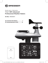
WIFI Multi Graph Weather Station 7-in-1
W-LAN Multi-Grak-Wetterstation 7in1
Art. No. 7003800
7803510
7009971
GB
INSTRUCTION MANUAL
DE
BEDIENUNGSANLEITUNG

DE
Besuchen Sie unsere Website über den folgenden QR Code oder Weblink um weitere Informationen zu
diesem Produkt oder die verfügbaren Übersetzungen dieser Anleitung zu nden.
GB
Visit our website via the following QR Code or web link to nd further information on this product or the
available translations of these instructions.
FR
Si vous souhaitez obtenir plus d’informations concernant ce produit ou rechercher ce mode d’emploi en
d’autres langues, rendez-vous sur notre site Internet en utilisant le code QR ou le lien correspondant.
NL
Bezoek onze internetpagina via de volgende QR-code of weblink, voor meer informatie over dit product of
de beschikbare vertalingen van deze gebruiksaanwijzing.
ES
¿Desearía recibir unas instrucciones de uso completas sobre este producto en un idioma determinado? Entonces
visite nuestra página web utilizando el siguiente enlace (código QR) para ver las versiones disponibles.
IT
Desidera ricevere informazioni esaustive su questo prodotto in una lingua specica? Venga a visitare il nostro
sito Web al seguente link (codice QR Code) per conoscere le versioni disponibili.
RU
Посетите наш сайт, отсканировав QR-код, или перейдите ссылке, чтобы больше узнать об этом товаре
или скачать руководство по эксплуатации на другом языке.
www.bresser.de/P7003800
www.bresser.de/P7803510
www.bresser.de/P7009971
www.bresser.de/warranty_terms
GARANTIE · WARRANTY · GARANTÍA · GARANZIA
RECYCLAGE (TRIMAN/FRANCE)
GB
INSTRUCTION MANUAL ......................4
DE
BEDIENUNGSANLEITUNG ................57
Product Art. No.
Base station
+ 7-in-1 Sensor
+ Thermo-Hyrosensor
7003800
Only/Nur 7-in-1 Sensor 7803510
Only/Nur Thermo-
Hygrosensor
7009971

3
https://www.wunderground.comhttps://weathercloud.net
WORKS WITH
APP DOWNLOAD
DELIVERY CONTENT · LIEFERUMFANG
Apple and the Apple logo are trademarks of Apple Inc., registered in the U.S. and other
countries. App Store is a service mark of Apple Inc., registered in the U.S. and other countries.
Google Play and the Google Play logo are trademarks of Google Inc.
https://www.awekas.at
AWEKAS
Weather Underground is a registered trademark of The Weather Channel, LLC. both in the United States and internationally. The Weather Underground Logo is a
trademark of Weather Underground, LLC. Find out more about Weather Underground at www.wunderground.com
https://www.pwsweather.com
https://www.bresser.de/download/ProWeatherLivehttps://proweatherlive.net
A C DB
Art. No. 7003800: Console (A), power adapter (B), 7-in-1 sensor (C), Thermo-Hygrosensor (D)
Basisstation (A), Netzteil (B), 7in1 Sensor (C), Thermo-/Hygro-Sensor (D)
Art. No. 7803510: 7-in-1 Sensor (C)
Art. No. 7009971: Thermo-Hygrosensor (D)

4
Table of content
1. Precaution & Warning ...............................................................6
1.1 Introduction...................................................................7
1.2 Quick start guide...............................................................7
2. Pre-installation ....................................................................7
2.1 Checkout ....................................................................7
2.2 Site selection .................................................................8
3. Getting started .....................................................................8
3.1 Wireless 7-in-1 sensor ..........................................................8
3.1.1 Install wind vane........................................................9
3.1.2 Install rain gauge funnel ..................................................9
3.1.3 Install batteries .........................................................9
3.1.4 Adjust the solar panel...................................................10
3.1.5 Sensor array installation.................................................11
3.1.6 Plastic mounting installation ..............................................12
3.1.7 Direction alignment.....................................................13
3.1.8 Pointing the wireless 7-in-1 sensor to south .................................13
3.2 Wireless indoor hygro-thermo sensor..............................................14
3.2.1 Install wireless indoor hygro-thermo sensor..................................14
3.3 Synchronizing additional sensor(s) (optional) .......................................14
3.3.1 Thermo-hygro and water sensors (optional) .................................15
3.3.2 Air quality sensors (optional) .............................................15
3.4 Recommendation for best wireless communication ...................................16
3.5 Power up the console..........................................................17
3.5.1 Install backup battery and power up........................................17
3.5.2 Setup the console......................................................17
3.6 Synchronizing wireless 7-in-1 sensor..............................................18
3.7 Data clearing ................................................................18
4. Display console functions and operation. . . . . . . . . . . . . . . . . . . . . . . . . . . . . . . . . . . . . . . . . . . . . . . .18
4.1 Screen display ...............................................................18
4.2 Display Console keys ..........................................................19
4.3 About the local time ...........................................................20
4.4 Console settings..............................................................20
4.5 View sunrise / sunset time ......................................................21
4.6 View year ...................................................................21
4.7 Moon phase .................................................................21
4.8 Wireless sensor signal receiving .................................................21
4.9 Trend Indicator ...............................................................22
4.10 View outdoor temperature and humidity............................................22
4.11 View indoor, optional thermo-hygro and leak channels ................................22
4.11.1 Water leak (optional leak sensor) .........................................22
4.12 Barometric pressure ...........................................................22
4.12.1 Absolute or relative barometric pressure mode...............................23
4.13 View feels like, dew point and optional sensor’s reading ...............................23
4.13.1 Feels Like ...........................................................24
4.13.2 Dew point ...........................................................24
4.13.3 Pollutant level indicator table for optional sensors ............................25
4.14 Wind .......................................................................25
4.14.1 Overview ............................................................25
4.14.2 Wind direction, Gust and Beaufort scale display..............................25
4.14.3 Beaufort scale table....................................................26
4.15 Rain .......................................................................27
4.15.1 Overview ............................................................27
4.15.2 The rain display mode ..................................................27
4.15.3 Rain rate level definition ................................................27
4.15.4 To reset the total rainfall record ...........................................27
4.16 Light intensity, UV index and exposure level ........................................27
4.16.1 UV index vs exposure table..............................................27
4.17 History graph ................................................................28
4.17.1 Graphs for different parameters over fixed time period.........................28
4.17.2 Graphs for chosen parameter over different time periods.......................29

5
GB
4.18 Weather forecast .............................................................30
4.18.1 Daily forecast for present day and next 7 days ...............................30
4.18.2 Hourly forecast for 24 hours .............................................31
4.18.3 Icon for multi-day / 24 hours weather forecast ...............................32
4.19 MAX / MIN records ............................................................32
4.19.1 View maximum / minimum records ........................................32
4.19.2 To clear the MAX / MIN records...........................................33
4.20 Alarm time and Weather Hi / Lo alert ..............................................33
4.20.1 To on/off time alarm and weather Hi / Lo alert................................33
4.20.2 To set alarm time and weather Hi / Lo alert..................................34
4.20.3 Suspend the time alarm ................................................34
4.20.4 Stop weather alert .....................................................35
5. Registering with weather server platforms ..............................................35
5.1 ProWeatherLive.net (PWL)......................................................35
5.2 WeatherUnderground.com (WU) .................................................37
5.3 Weathercloud (WC) ...........................................................39
5.4 Awekas.....................................................................41
5.5 PWSWeather ................................................................41
6. Connect display console to internet by WI-FI ............................................41
6.1 Download WSLink configuration app ..............................................41
6.2 Console in Access Point (AP) broadcast mode ......................................41
6.3 Add your console to WSLink ....................................................42
6.3.1 Setup new console with WSLink ..........................................43
6.4 Weather server setting .........................................................44
6.5 API for customized weather server................................................46
6.6 Calibration ..................................................................46
6.7 Firmware....................................................................47
6.8 STA mode operation ...........................................................48
7. View weather server live data & operation ..............................................48
7.1 View ProWeatherLive live data...................................................48
7.2 Viewing your weather data in WUnderground .......................................49
7.3 Viewing your weather data in Weathercloud ........................................49
7.4 Viewing weather data via WSLink app .............................................50
7.5 ProWeatherLive dashboard apps.................................................50
8. Other functions ...................................................................50
8.1 Backlight....................................................................50
8.2 Maintenance.................................................................50
8.2.1 Battery replacement ....................................................50
8.2.2 Changing batteries and manual pairing of sensor .............................50
8.2.3 Remove wireless sensor(s) connection .....................................50
8.3 Firmware update..............................................................51
8.4 Reset and factory hard reset ....................................................51
8.5 Wireless 7-in-1 sensor array maintenance..........................................52
9. Troubleshoot .....................................................................52
10. Specifications ....................................................................53
10.1 Console ....................................................................53
10.2 Wireless 7-in-1 sensor .........................................................55
10.3 Wireless thermo-hygrometer sensor ..............................................55
11. DISPOSAL ......................................................................56
12. CE Declaration of Conformity ........................................................56
13. Warranty & Service ................................................................56
About this user’s manual
This symbol represents a warning. To ensure safe use, always adhere to the
instructions described in this documentation.
This symbol is followed by a user’s tip.

6
1. Precaution & Warning
- Keeping and reading the “User manual” is highly recommended. The manufacturer and supplier
cannot accept any responsibility for any incorrect readings, export data lost and any consequences
that occur should an inaccurate reading take place.
- This instruction manual contains useful information on the proper use and care of this product.
Please read this manual through to fully understand and enjoy its features, and keep it handy for
future use.
-
- The contents of this manual may not be reproduced without the permission of the manufacturer.
-
- This product is not to be used for medical purposes or for public information
- Do not subject the unit to excessive force, shock, dust, temperature or humidity.
- Do not cover the ventilation holes with any items such as newspapers, curtains etc.
- Do not immerse the unit in water. If you spill liquid over it, dry it immediately with a soft, lint-free cloth.
- Do not clean the unit with abrasive or corrosive materials.
- Do not tamper with the unit’s internal components. This invalidates the warranty.
-
manufacturer will not be responsible. Consult the furniture manufacturer’s care instructions for
information.
-
- This product is intended for use only with the adaptor provided: Manufacturer: DONGGUAN SHIJIE
HUAXU ELECTRONICS FACTORY, Model: HX075-0501000-AX.
- The socket-outlet shall be installed near the equipment and easily be accessible.
- When replacement parts are required, be sure the service technician uses replacement parts
- This product is not a toy. Keep out of reach of children.
- The console is intended to be used only indoors.
- Place the console at least 20cm from nearby persons.
- This device is only suitable for mounting at height < 2m.
- When disposing of this product, ensure it is collected separately for special treatment.
-CAUTION! Risk of explosion if battery is replaced by an incorrect type.
-
not open or damage batteries. Excessive heat or damage can cause explosion.
-
can result in an explosion.
- Do not swallow batteries. There is is a risk of chemical burn.
- This product contains a coin/button cell battery. If the coin/button cell battery is swallowed, it can
cause severe internal burns in just 2 hours and can lead to death.
- Keep new and used batteries away from children.
- If the battery compartment does not close securely, stop using the product and keep it away
from children.
- If you think batteries might have been allowed or placed inside any part of the body, seek
immediate medical attention.
- Only use fresh batteries. Do not mix new and old batteries.
- Dispose of used batteries according to the instructions.
- Replacement of a battery with an incorrect type that can result in an explosion or the leakage of

7
GB
1.1 Introduction
Thank you for selecting 24H 7-Day Forecast Multi-graph WI-FI Weather Station. This system
gathers many advance features for weather observer, such as ProWeatherLive (PWL) cloud
service which provide on-line weather forecast and condition of your area onto your console
while at the same time receiving your personal weather data upload to be viewed on PWL
website or PWL app anytime. The 7-in-1 professional wireless sensor-array integrates
temperature, humidity, wind, rain, UV and light sensors together, to continually monitoring your
local weather conditions at all time and transmit these data to your console through wireless
radio frequency technology. This system also support up to 3 thermo-hygro sensor(s) and other
advance optional sensor(s) such as water leak sensors and air quality sensors which include
PM2.5/10, CO, HCHO/VOC level and CO wireless sensors, so you may monitor all your
environment condition in one system, one app.
1.2 Quick start guide
The following Quick Start Guide provides the necessary steps to install and operate the
weather station, and upload to the internet, along with references to the pertinent sections.
Step Description Section
1 Power up the wireless 7-in-1 sensor. 3.1.3
2 Power up the display console and pair with sensor. 3.5, 3.6
3 Register your console at weather server proweatherlive.net to obtain
Station ID and key.
5.1
4 6.1, 6.2, 6.3,
6.4(c1)
2. Pre-installation
2.1 Checkout
Before permanently install your weather station, we recommend the user to operate the
weather station at a location which is easy to access to. This will allow you to get familiar with
the weather station functions and calibration procedures, to ensure proper operation before
installing it permanently.

8
2.2 Site selection
Before installing the sensor array, please consider the followings:
1. Batteries must be changed about every 2 to 2.5 years
2.
array should be installed at 1.5m (5’) from any building, structure, ground or roof top.
3. Transmission range between sensor array and console could reach a distance of 150m
(or 450 feet) at line of sight, providing there are no interfering obstacles in between or
nearby such as trees, towers, or high voltage line. Check the reception signal quality to
ensure good reception.
4. Household appliance such as fridge, lighting, dimmers may pose Electro-magnetic
interference (EMI), while Radio Frequency Interference (RFI) from devices operating in
the same frequency range may cause signal intermittent. Choose a location at least 1-2
meter (3-5 feet) away from these interference sources to ensure best reception.
3. Getting started
3.1 Wireless 7-in-1 sensor
16
15
14
12
13
11
10
2
3
6
1
4
5
7
9
8
1. Rain collector
2. Balance indicator
3. UVI / light sensor
4. Wind vane
5. Wind cups
6. Antenna
7. Solar panel
8. Radiation shield and
thermo-hygro sensor
9. Drain holes
10. Battery door
11. Red LED indicator
12. [ RESET ]
13. Mounting clamp
14. Adjustable hinge of solar
panel
15. Tipping bucket
16. Rain sensor

9
GB
3.1.1 Install wind vane
With reference to photo below, (Step 1)
(Step 2) tighten the set
screw with a precision screwdriver.
Step 1 Step 2
3.1.2 Install rain gauge funnel
Install the rain gauge funnel and rotate clockwise to lock the funnel to the sensor array.
Step 2
Step 1
Lock
grooves
3.1.3 Install batteries
Unscrew the battery door at bottom of unit. Insert the 3 x AA batteries (non-rechargeable)
according to the +/- polarity indicated. The red LED indicator on the back of the sensor array
Note:
We recommend using non-rechargeable Lithium AA batteries for cold weather climate, but

10
3.1.4 Adjust the solar panel
The tilting angle of solar panel can be adjusted vertically from 0 into 15°, 30°, 45° and 60°
positions depending on the area you are living in. For optimal power output year-round, please
set the tilt angle that is closest to your latitude.
E.g.,
Location (latitude, longitude) Solar panel tilt angle
Berlin (52.5484, 13.3736) 60°
Chicago (42.1146, -88.0464) 45°
30°
Bangkok (14.2752, 100.5684) 15°
Sydney (-33.5738, 151.3053)* 30°
*Sensors installed in Southern Hemisphere must have their solar panels facing North.
Step 1: Loosen and push the screw lightly inward until
the gears on the opposite side separated from lock
position.
Step 2: Adjust the vertical angle of the solar panel
(0°, 15°, 30°, 45°, 60°) according to the latitude of
your location.
Step 3: Push the gear and tighten the screw until the
gears are securely locked.

11
GB
3.1.5 Sensor array installation
Mounting kit set
1. Pole mounting stand x 1 2. Mounting clamp x 1 3. Plastic pole x 1
4. screws x 4 5. Hex nuts x 4 6. Flat washers x 4
7. screw x 1 8. Hex nut x 1 9. Rubber pad x 4

12
3.1.6 Plastic mounting installation
1.
nuts. Following below 1a, 1b, 1c sequences:
1a. I
nsert the plastic pole into the hole of the
mounting stand, and then secure it with the screw
and nut.
1c. Fasten the mounting stand
pole with 4 long screws and nuts.
1b. Apply 2 rubber pads on the mounting clamp.
2. Apply 2 rubber pads on the inner
sides of the mounting base and
clamp of the sensor-array, and
loosely fasten them together.
3. Place the sensor-array over the mounting pole
and align it to North direction before fastening
the screws.

13
GB
Note:
- Any metal object can attract lightning strikes, including your sensor-array mounting pole. Never
install sensor-array in stormy days.
- If you want to install a sensor-array on a house or building, consult a licensed electrical engineer to
ensure proper grounding. Direct lightning impact on a metal pole can damage or destroy your home.
- Installing the sensor at high location may result in personal injury or death. Perform as many initial
inspections and operations as possible on the ground and in buildings or houses. Only install the
sensor-array on clear, dry days.
- Ensure the sensor-array installation place is stable and no vibration.
3.1.7 Direction alignment
Install the wireless 7-in-1 sensor in an open
location with no obstructions above and around the
sensor for accurate rain and wind measurement.
Locate the North (N) marker on top of the 7-in-1
sensor and align the marker to point North upon
the mounting bracket around the diameter pole
using two screw and nuts provided.
Use the bubble level on the 7-in-1 sensor to make
sure the sensor is completely level for proper
measurement of rainfall.
North marker on top of the 7-in-1 sensor.
Use the bubble level on the 7-in-1 sensor to make
sure the sensor is completely level for proper
measurement of rainfall.
Point to
SOUTH
Point to
NORTH
2 meter
off the
ground
mounting pole
not included
3.1.8 Pointing the wireless 7-in-1 sensor to south
The outdoor 7-in-1 sensor is calibrated to point to North for the maximum accuracy. However,
for the user's convenience (e.g. users in the Southern hemisphere), it is possible to use the
sensor with the wind vane pointing to South.
1. Install the 7-in-1 wireless sensor with its wind meter end pointing to South. (Please refer to
Section 3.1.7 for mounting details).
2. Select "S' in set hemisphere step (Please refer to Section 4.4 for setup details).
3.
Note:
Changing the hemisphere setting will automatically switch the direction of the moon phase on
the display.

14
3.2 Wireless indoor thermo-hygro sensor
2
5
6
4
7
1
3
1. LCD display
2. Transmission status LED
3. Wall mounting holder
4. [ CHANNEL ] slide switch
5. [ RESET ]
6. [ °C / °F ]
7. Battery compartment
3.2.1 Installing wireless indoor thermo-hygrosensor
1. Remove the battery door of the sensor.
2. Use the channel slide switch to set the channel number for the sensor (e.g. Channel 1)
3. Insert 2 x AA size batteries into the battery compartment and close the battery door
according to the polarity information marked on the battery compartment.
4. The sensor is in synchronization mode, and can be registered to the console within the next
Note:
- If you need to re-assign the sensor channel, slide the channel slide switch to the new channel
[ RESET ] on the sensor.
- Avoid placing this sensor in direct sunlight, rain or snow.
3.3 Synchronizing additional sensor(s) (optional)
Some of these sensors are multi-channel. Before inserting the batteries, set the channel
number if channel slide switch is located at back of sensors (inside battery compartment). For
their operations please refer to the manuals that come with the products.

15
GB
3.3.1 Thermo-hygro and water sensors (optional)
Art. No. No. of sensor support Description Image
7009971
Up to 3 sensors
Thermo-Hygro Sensor
7009972 Soil Moisture and Temperature Sensor
7009973 Pool Sensor
7009975 Up to 3 sensors Water detector
3.3.2 Air quality sensors (optional)
Art. No. No. of sensor support Description Image
7009970 1 sensor PM2.5 / 10 sensor
7009977 1 sensor CO2 Sensor

16
7009978 1 sensor HCHO with VOC Sensor
Note:
For air quality sensors pairing, you can assign the sensors in any channel. The console support
to display one channel of each of air quality sensor.
3.4 Recommendation for best wireless communication
distance and barriers between the sensor transmitter and the console.
1. Electromagnetic interference (EMI) – these may be generated by machinery, appliances,
lighting, dimmers and computers, etc. So please keep your console 1 or 2 meters away from
these items.
2. Radio-frequency interference (RFI) – if you have other devices operating on 868 / 915 / 917
MHz, you might experience communication intermittent. Please re-located your transmitter
or console to avoid signal intermittent problem.
3. Distance. Path loss occurs naturally with distance. This device is rated to 150m (450 feet) by
line of sight (in interference free environment and without barriers). However, typically you will
get 30m (100 feet) maximum in real life installation, which includes passing through barriers.
4. Barriers. Radio signal are blocked by metal barriers such as aluminum cladding. Please
align the sensor array and console to get them in clear line of sight through window if you
have metal cladding.
The table below show a typical level of reduction in signal strength each time the signal passed
through these building materials.
Materials Signal strength reduction
Glass (untreated) 10 ~ 20%
Wood 10 ~ 30%
Plasterboard / drywall 20 ~ 40%
Brick 30 ~ 50%
Foil insulation 60 ~ 70%
Concrete wall 80 ~ 90%
Aluminum siding 100%
Metal wall 100%
Remarks: RF signal reduction for reference

17
GB
3.5 Power up the console
3.5.1 Install backup battery and power up
1. Backup battery provides power to the console to retain clock time and date, MAX/MIN
records and calibration value.
Step 1 Step 2 Step 3
Remove the console
battery door with coin
Insert a new CR2032
button cell battery
Replace the battery door.
Note:
- The backup battery can backup: Time & Date and MAX/MIN records.
- The built-in memory can backup: Calibration value and connection settings.
- Please always remove the backup battery if the device is not going to be used for a while. Please
keep in mind that even when the device is not in use, certain settings, such as the clock, calibration
and records in its memory, will still drain the backup battery.
2. Plug in the power adapter to power up the console.
3.5.2 Setup the console
1. Once the console is power up, all the segments of the LCD will be shown.
2. The console will automatically enter AP mode and sensor synchronization mode
automatically.

18
Note:
If no display appears when power up the console, you can press [ RESET ] by using a pointed
object. If this process still not work, you can remove the backup battery and unplug the adaptor
then re-power up the console again.
3.6 Synchronizing wireless 7-in-1 sensor
Immediately after power up the console, while still in synchronization mode, the 7-in-1 sensor
). User may
also manually restart the synchronization mode by pressing the [ SENSOR / WI-FI ]. Once they
are paired up, the sensor signal strength indicator and weather reading will appear on your
console display.
3.7 Data clearing
During installation of the wireless 7-in-1 sensor, the sensors were likely to be triggered, resulting
in erroneous rainfall and wind measurements. After the installation, user may clear out all the
erroneous data from the display console. Simply press the [ RESET ] once to re-start the console.
4. Display console functions and operation
4.1 Screen display
18
29
31
0
41
1
5
6
7
1. Outdoor temperature & humidity
2. Weather index and optional air quality
sensor(s) readings (e.g.PM2.5 /10, CO2,
HCHO + VOC, CO)
3. UV index & light intensity (SUN)
4. Time calendar, moon phase & sunrise/
Sunset
5. Wind speed
6. Wind direction, Beaufort & Gust
7. Weather forecast
8. Indoor / CH temperature & humidity
9. Barometer
10. Rainfall & Rain rate
11. Weather history graph

19
GB
4.2 Display Console keys
No.Key / Part name Description
1ALARM/SNOOZE Press to stop alarm sound.
224-HOUR View hourly forecast.
37-DAY View daily forecast.
4MEM Press to switch between past 24 hours or since last reset maximum
and minimum weather data records.
5MODE Press to switch between feels like, dew point and optional air quality
sensor readings.
6CHANNEL Press to switch between indoor and channels readings.
7RAIN Press to switch between rain rate and rainfall.
8HISTORY
9GRAPH
10 Display screen
11 Ambient light detector
12 BACKLIGHT Slide to select the backlight in HI / LO / Auto mode.
13 SET Press to show sunrise / sunset time.
Hold to enter time and date settings.
14 ALARM Press to view alarm / alert settings.
Hold to enter alarm / alert settings.
15 WIND Press to switch between wind direction, wind gust, 10 minutes gust
and Beaufort scale.
16 Wall mount hole
17 Decrease the value in setting.
18 Increase the value in setting.
19 RESET Press to reset the console.
Hold 6 seconds to factory reset the console.
20 SENSOR / WI-FI Press to start sensor synchronization (pairing).
Hold 6 seconds to enter AP mode, vice versa.

20
21 Battery compartment
22 Power jack
23 REFRESH Press to update the upload data and time synchronization.
24 BARO Switch between relative and absolute air pressure reading.
25 Table stand
4.3 About the local time
The console will automatically synchronize to your local time after successfully connected to
Date Day of
the week
Moon
phase
Time alarm
indicator
Time
Time
Synchronized
Sunrise / Sunset
time indicator
4.4 Console settings
The setting mode can set the time, date, unit of measure and other functions.
Press and hold [ SET ] for 2 seconds to enter the setting Mode. In setting mode, press [SET]
to proceed to the next setting step. Press [ ] or [ ] to change the value. Press and hold the
key for quick-adjust. Please refer to following setting procedures below:
Step Mode Setting procedure
[SET]
+2s
12/24 hour
format
Press [ ] or [ ] to select 12 or 24 hour format.
[SET] Time Press [ ] or [ ] to adjust the minute / hour.
[SET] Year Press [ ] or [ ] to adjust the year.
[SET] Date Press [ ] or [ ] to adjust the day / month.
[SET] M-D D-M Press [ ] or [ ] to select "Month / Day" or "Day / Month" display
format.
[SET] Time sync ON/
OFF
Press [ ] or [ ] to enable or disable time sync function.
If you want to set the time manually, you should set time sync OFF.
[SET] Hemisphere
Press [ ] or [ ] to select North / South hemisphere for moon phase.
[SET] Weekday
Language
Press [ ] or [ ] to select weekday display language.
[SET]
Temperature unit
Press [ ] or [ ]
[SET] HCHO unit Press [ ] or [ ] to change the unit between ppb and mg/m3.
[SET] CO unit Press [ ] or [ ] to change the unit between ppm and mg/m3.
[SET] CO unit Press [ ] or [ ] to change the unit between ppm and mg/m3.
[SET] Wind speed unit
Press [ ] or [ ] to change the unit between m/s, km/h, knots
and mph.
[SET] Air pressure unit
Press [ ] or [ ] to change the unit between hPa, mmHg and inHg.
[SET]
Light intensity unit
Press [ ] or [ ] to change the unit between Klux,W/m2 and Kfc.
[SET] Rain unit Press [ ] or [ ] to change the unit between mm and inch.
[SET] Exit setting
Note:
- Console will exit setting mode automatically, if no operation after 60 seconds.
- Press and hold [ SET ] for 2 seconds to exit the setting mode at any time.
/