
Honeywell
730xxxxxx ©
Elster GmbH | All rights reserved. Subject to modification
1
English
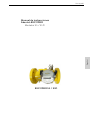
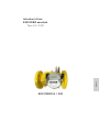
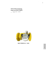
Instruction Manual
Absolute ENCODER
Type S1 / S1D
Betriebsanleitung
Absolut ENCODER
Typ S1 / S1D
Mode d’emploi
ENCODEUR absolu
Type S1 / S1D
Manual de instrucciones
Absolut-ENCODER
Modelos S1 / S1D
Istruzioni d’uso
ENCODER assoluto
Tipo S1 / S1D
Gebruiksaanwijzing
Absoluut ENCODER
Type S1 / S1D

Honeywell
2
730xxxxxx © Elster GmbH | All rights reserved. Subject to modification

Honeywell
730xxxxxx ©
Elster GmbH | All rights reserved. Subject to modification
3
English
Français
Español
Italiano Nederlands Deutsch
Instruction Manual
Absolute ENCODER
Type S1 / S1D
Betriebsanleitung
Absolut ENCODER
Typ S1 / S1D
Mode d’emploi
ENCODEUR absolu
Type S1 / S1D
Manual de instrucciones
Absolut-ENCODER
Modelos S1 / S1D
Istruzioni d’uso
ENCODER assoluto
Tipo S1 / S1D
Gebruiksaanwijzing
Absoluut ENCODER
Type S1 / S1D

Honeywell
4
730xxxxxx © Elster GmbH | All rights reserved. Subject to modification

Honeywell
73024510a © Elster GmbH | All rights reserved. Subject to modification
5
English
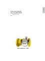
ENCODER S1 / S1D
Instruction Manual
Absolute ENCODER
Type S1 S1D
E1


Honeywell
73024510a © Elster GmbH | All rights reserved. Subject to modification
7
English
Contents
1. Safety instructions ................................................................................................ 9
1.1 Intended use ................................................................................................... 10
1.2 Approvals and certifications ........................................................................... 10
1.3 Copyright and data protection ....................................................................... 11
1.4 Exemption from liability ................................................................................. 11
1.5 Product liability and guarantee ...................................................................... 12
1.6 Personnel ........................................................................................................ 12
1.7 Intended use and field of application ............................................................. 12
1.8 Legal declarations ........................................................................................... 12
1.9 Recycling and environmental protection ....................................................... 12
2. Structure and function ........................................................................................ 13
2.1 Device description .......................................................................................... 13
2.2 Working principle ........................................................................................... 13
2.3 Versions .......................................................................................................... 14
2.4 Connection configurations ............................................................................. 14
2.5 Top-mounted ENCODER ................................................................................. 16
3. Installation and commissioning ........................................................................... 16
4. Storage................................................................................................................ 17
5. Cleaning .............................................................................................................. 17
6. Repair ................................................................................................................. 17
7. Technical data ..................................................................................................... 17
8. Ambient conditions ............................................................................................. 18
9. Approvals ............................................................................................................ 18
10. Annex A – Standards and Norms ....................................................................... 19

Honeywell
8
73024510a © Elster GmbH | All rights reserved. Subject to modification
Information on the documentation
The latest version of the operating instructions is available to download from the
Honeywell website.
Please read the information in this document carefully in order to avoid injury to
the user or damage to the device. Moreover, currently valid national standards,
safety regulations and accident prevention regulations must be adhered to.
Should you have any problems understanding the contents of this document,
please contact your local Honeywell branch for support. Honeywell cannot
accept any responsibility for damage to property or personal injuries which are a
result of the information in this document not having been understood properly.
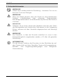
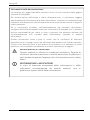
This document helps you to set up the operating conditions in such a way that
the safe and efficient use of the device is assured. In addition, this document also
specifies points and safety measures which must be particularly observed and
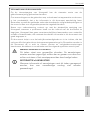
which are indicated using the following symbols:
WARNING or CAUTION
This symbol warns of dangerous situations. Failure to follow the
instructions could result in danger to people and the
environment or the meter could suffer damage.
INFORMATION or NOTE
Accurate measurement cannot be ensured if information or
notes with this symbol are ignored.

Honeywell
73024510a © Elster GmbH | All rights reserved. Subject to modification
9
English
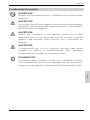
1. Safety instructions
WARNING!
Danger of electrostatic discharge – only use a damp cloth to clean.
WARNING!
If there is danger that the device can be damaged from falling
(pointed, sharp-edged or heavy) objects, the operator must protect
the device.
WARNING!
Exposure to danger which can result from a chemical reaction
between parts of the meter and chemical substances in the vicinity
must be discussed with the manufacturer and the cause must be
eliminated.
WARNING!
The gas meter in which the encoder is installed must be integrated
into the equipotential bond, e.g. by connecting it to the grounded
pipeline.
INFORMATION!
Compliance with the specified operating and ambient conditions
as indicated on the type label and the gas meter type label is
absolutely essential for the safe operation of the encoder.

Honeywell
10
73024510a © Elster GmbH | All rights reserved. Subject to modification
1.1 Intended use
INFORMATION!
The manufacturer shall not be liable for damage caused by
improper or inappropriate use.
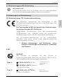
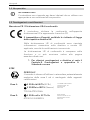
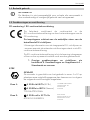
1.2 Approvals and certifications
CE marking / EU declaration of conformity
The manufacturer certifies conformity
with the EU
declaration of conformity and by attaching the CE marking.
The pulse generator meets the statutory requirements of
the relevant EU guidelines.
Comprehensive information on the applicable EU
Directives and Standards, as well as recognized
certifications, is contained in the EU declaration of
conformity.
The EU declaration of conformity is included in the delivery
and is also available to download at www.docuthek.com.
See Chapter 9 for more approvals and Directives.
Approvals and Annex A – Standards and Norms
ATEX
DANGER!
The encoder is suitable for use in Zone 1 or 2 hazardous
areas and is approved with the following certification:
Zone 1:
II 2G Ex ib IIB T4
(SCR+)
II 2G EEx ia IIB T4 (Namur)
TÜV 04 ATEX 2544
TÜV NORD CERT GmbH
Langemarckstr. 20
45747 Essen
Germany
Zone 2
:
II 3G Ex nA ic IIC T4 Gc
ATEX ELS 18.0001X
Elster GmbH
Steinern Straße 19-21
55252 Mainz-Kastel
Germany

Honeywell
73024510a © Elster GmbH | All rights reserved. Subject to modification
11
English
1.3 Copyright and data protection
This document has been created with the greatest possible care. No liability
is assumed for the accuracy, completeness or currency of the contents.
The contents and works produced in this document are subject to copyright.
Contributions by third parties are identified as such. The reproduction,
processing, distribution and any form of use beyond that which is permitted
by copyright require the written authorization of the respective author or the
manufacturer. The manufacturer strives to always respect the copyright of
others or to use his own or licence-free works.
We would like to point out that data transfer via the Internet (e.g. through e-
mail communication) can be subject to breaches in security. It is not
possible to provide complete protection against access by third parties.
1.4 Exemption from liability
The manufacturer shall not be liable for damage of any type caused by the
use of this product, including but not restricted to, direct, indirect or
incidental damage and its consequences.
This exemption from liability does not apply if the manufacturer has acted
intentionally or with gross negligence. In the event that any applicable law
does not allow such restrictions on implied warranties for defects, or the
exclusion or limitation of certain payments for damages, and should such
law apply to you, the above-mentioned exemption from liability, exclusions
or limitations may not apply to you in part or in whole.
For every product purchased, the warranty is valid in accordance with the
corresponding product documentation as well as the conditions of sale and
delivery of the manufacturer.
The manufacturer reserves the right to amend without prior notice the
contents of the documents, including this exemption from liability, in any
form and at any point in time, and for any reason, and shall in no way be liable
for any possible consequences of such amendments.

Honeywell
12
73024510a © Elster GmbH | All rights reserved. Subject to modification
1.5 Product liability and guarantee
The responsibility as to whether the device is suitable for the intended use is
that of the operator. The manufacturer cannot accept any liability for the
consequences of misuse by the operator. Improper installation or operation
of the devices (systems) render the warranty void. Furthermore, the relevant
“General Terms and Conditions” which form the basis of the purchase
contract also apply.
1.6 Personnel
This manual is aimed at staff who have adequate specialist and technical
knowledge (in Germany, for instance, in accordance with DVGW Codes of
Practice 492 and 495 or comparable technical regulations) on the basis of
their training and experience in the sector of energy and gas distribution.
1.7 Intended use and field of application
This product is intended to be used for the installation on/in gas meters from
Elster/Honeywell.
This product is not intended to be used for installation on/in (gas) meters
from other manufacturers.
1.8 Legal declarations
The metrological conformity assessment is based on the regulations of the
country concerned, where the device will be used.
1.9 Recycling and environmental protection
Honeywell has designed the transport packaging of the device to be
environmentally friendly. Packaging materials are always selected
consistently with a view to recycling. The cardboard items used constitute
secondary raw materials for the paperboard and paper industry. The
Instapak® foam packaging is recyclable and can be reused.
Plastic sheeting and strips/bands are also made of recyclable plastic. At
Honeywell, subsequent recycling and disposal are already elements of the
product development process. When selecting the materials, we allow for
reusability of the materials, suitability of materials and subassemblies for
dismantling and separation, and the risks of environmental pollution and
health risks when recycling and dumping on landfill sites.

Honeywell
73024510a © Elster GmbH | All rights reserved. Subject to modification
13
English
2. Structure and function
The ENCODER S1/S1D products are opto-electronic read-out units with
digital data transfer for turbine and rotary gas meters from Elster/Honeywell.
2.1 Device description
The encoder is integrated in an Elster/Honeywell meter index. The
technology is based on opto-electronic scanning which identifies the
position of the individual rollers on the mechanical index in a contact-free
process. The reading process for the Absolute ENCODER is therefore
identical to the manual reading of the mechanical index on site. Operation
of the Absolute ENCODER requires neither a battery nor an individual power
supply, as the power required for reading is supplied by the connected
device. The described technology can be flexibly adjusted to the application
by choosing one of the optional interface types.
2.2 Working principle
The digit rollers of the mechanical index are individually scanned by opto-
electronic means. Each roller has three asymmetrically arranged slots of
different lengths which are then scanned by five beams of light to determine
their position. The respective position of the roller and thus the digits on the
roller can be clearly identified thanks to the specific arrangement of the slots.
The light barriers consist of phototransistors, LEDs and optical waveguides
which are all scanned and evaluated one after the other using time-series
analysis. Control and evaluation of the light barriers is carried out by a
controller. This exactly defines the position of each individual digit roller and
transmits it to the connected add-on device (e.g. volume conversion device,
data logger or bus system) as part of a defined protocol. Depending on the
interface type, the protocol already includes various meter data such as the
factory number and meter size. The plug-and-play system means that no
subsequent parameterization is required.

Honeywell
14
73024510a © Elster GmbH | All rights reserved. Subject to modification
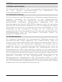
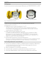
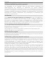
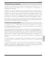
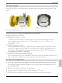
2.3 Versions
The ENCODER is available in two different mechanical versions, S1 and
S1D:
Fig. 1 | ENCODER S1 and ENCODER S1D
The ENCODER is available with the following communications protocols:
NAMUR (Ex Zone 1 or 2)
Unidirectional serial interface for direct connection to volume
conversion devices and data loggers (levels comply with EN 60947-5-5).
SCR+ (Ex Zone 1 or 2)
Low power interface, widely used for water meters, uses a protocol which
complies with IEC 62056-21 (formerly IEC 1107). The SCR interface can
be made compatible with the CL interface using a small separate,
external circuit.
M-Bus (without explosion protection)
For correcting multiple meters to an electronic evaluation system, e.g. in
industry or in a residential environment.
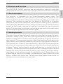
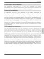
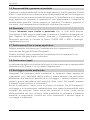
2.4 Connection configurations
Use only a screened cable to connect the encoder and ensure that the
pin assignment is correct (see Fig. 2 and sticker next to the cover of the
terminal box).
Only connect one conductor per terminal.
The maximum wire cross-section is 2.5 mm².
Wire end ferrules must be used for flexible cables.
TRZ with ENCODER S1 RABO with ENCODER S1D

Honeywell
73024510a © Elster GmbH | All rights reserved. Subject to modification
15
English
Tighten the screw terminals with a tightening torque of at least 0.8 Nm
to maximum 1 Nm.
Ensure the correct polarity of the two-wire connection on the Namur
interface. The M-Bus and SCR/SCR+ interfaces are independent of the
polarity.
It is possible to apply screening and to run a cable to the meter housing
or the pipe. It must be checked in advance that the grounding system
used allows grounding on both sides (ground loops and potential
difference in grounding).
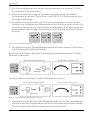
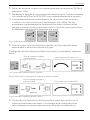
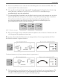
Fig. 2 | Terminal assignment
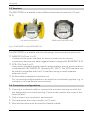
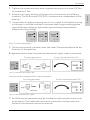
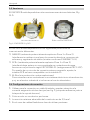
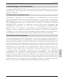
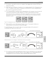
On the version with a double index, the lower 2 terminals determine the
direction of the gas flow:
Bridge attached to lower terminals (as delivered): upper index is activated:
Fig. 3 | Flow direction right > left
Lower terminals unassigned: lower index is activated:
Fig. 4 | Flow direction left > right
An IN-Sxx pulse generator may be installed on the encoder index cover
as an option. The installation work and connection configuration are
shown in the relevant instruction manual.
For rotary gas meters: For top-mounted encoder S1D:
For rotary gas meters: For top-mounted encoder S1D:

Honeywell
16
73024510a © Elster GmbH | All rights reserved. Subject to modification
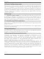
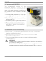
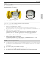
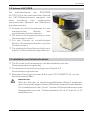
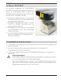
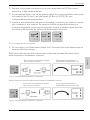
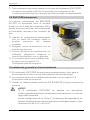
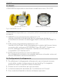
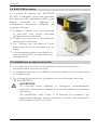
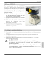
2.5 Top-mounted ENCODER
The top-mounted version of the
ENCODER S1/S1D is suitable for the
mechanical index drive of the MI2 index
cover and can be operated in addition to
the mechanical index installed in the gas
meter.
Connect the connector of the top-
mounted unit to the mechanical index
drive of the driving unit.
Use a locking screw to prevent it from
being pulled out.
Secure the locking screw with a seal for
use in custody transfer applications.
The electrical connection is made as
described in section 2.4 Connection
configurations.
3. Installation and commissioning
The encoder is supplied fully parameterized and ready for operation
together with the gas meters.
The electrical connection is made as described in section 2.4
Connection configurations.
For connecting the devices, use a screened cable pursuant to
IEC EN 60079-14.
WARNING!
If the encoder is used in hazardous areas, it must be connected to
an intrinsically safe circuit.
For installations in Zone 1, safety barriers or supply units must be
certified pursuant to ignition protection rating Ex ib IIC or Ex ia IIC.
Fig. 5 | Top-mounted ENCODER S1D

Honeywell
73024510a © Elster GmbH | All rights reserved. Subject to modification
17
English
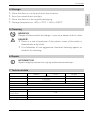
4. Storage
Store the device in a dry and dust-free location.
Avoid constant direct sunlight.
Store the device in its original packaging.
Storage temperature: -40 to +70°C / -40 to +158°F.
5. Cleaning
WARNING!
Danger of electrostatic discharge – only use a damp cloth to clean.
DANGER!
There is a risk of explosion if the plastic cover of the index is
cleaned with a dry cloth.
It is forbidden to use aggressive chemical cleaning agents or
solvents for cleaning.
6. Repair
INFORMATION!
Repairs may be carried out only by authorized workshops.
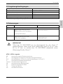
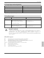
7. Technical data
Namur
SCR+
M
-
Bus
Ui
≤ 13.5 V
≤ 38 V
Ii
≤ 20 mA
≤ 20 mA
Pi
≤ 0.27 W
≤ 0.76 W
Enclosure
IP67
Top
-
m
ounted encoder:
Torque
0.2 Nmm
Max. speed of the
index drive 1 Hz
Drive value
0.1 / 1 / 10
Decimal places
0.2 / 1 / 0
Table 2 | Technical data

Honeywell
18
73024510a © Elster GmbH | All rights reserved. Subject to modification
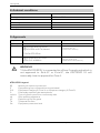
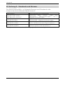
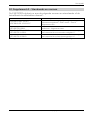
8. Ambient conditions
Ambient temperature
-
40°C to +60°C
Storage temperature
-
40°C to +60°C
Humidity
0 t
o 80% RH
Max. height above sea level
2000 m
Outdoor installation
Yes
Mechanical environments
M1
Table 3 | Ambient conditions
9. Approvals
Approval:
Approval number:
Approval body:
ATEX
Zone 1*:
II 2G Ex ib IIB T4 (SCR+)
II 2G EEx ia IIB T4 (Namur)
TÜV 04 ATEX 2544
TÜV NORD CERT GmbH
Langemarckstr. 20
45747 Essen | Germany
Zone 2*:
II 3G Ex nA ic IIC T4 Gc
ATEX ELS 18.0001X
Elster GmbH
Steinern Straße 19-21
55252 Mainz-Kastel | Germany
Table 4 | Approvals
WARNING!
* If the ENCODER S1 is connected to a Zone 2 supply unit which is
not approved to Ex ib IIC or Ex ia IIC, the ENCODER S1 will
irrevocably lose its approval for Zone 1.
ATEX/IECEx legend:
Marking of explosion protection
II
Equipment group: industrial (mining excluded)
2/3
Equipment category 2 (Zone 1) or equipment category 3 (Zone 2)
G
Potentially explosive gas atmospheres
ia/ib/ic
Type of ignition protection: intrinsically safe
nA
Non-sparking apparatus
IIC
Explosion group for gases
T4
Temperature class
Gb
Equipment protection level

Honeywell
73024510a © Elster GmbH | All rights reserved. Subject to modification
19
English
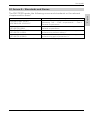
10. Annex A – Standards and Norms
The ENCODER meets the following norms and standards or the relevant
chapters within them*:
2014/30/EU
Electrom
agnetic compatibility
DIN EN 61326-1:2013
VDE 0843-20-1:2013-07
Electrical equipment for measurement, control and
laboratory use – EMC requirements – Part 1:
General requirements
DIN EN 60079
-
0:2012
+ A11:2013
IEC 60079-0:2011
Explosive atmospheres
–
Par
t 0: Equipment
–
General requirements
DIN EN 60079-11:2012
IEC 60079-11:2011
Explosive atmospheres
–
Part 11: Equipment
protection by intrinsic safety “i”
DIN EN 60079
-
15:2010
IEC 60079-15:2010
Explosive atmospheres
–
Part 15: Equipment
protection by type of protection “n”
* Standards valid at the time of the operating instructions going to press.

Honeywell
20
73024510a © Elster GmbH | All rights reserved. Subject to modification
Seite laden ...
Seite laden ...
Seite laden ...
Seite laden ...
Seite laden ...
Seite laden ...
Seite laden ...
Seite laden ...
Seite laden ...
Seite laden ...
Seite laden ...
Seite laden ...
Seite laden ...
Seite laden ...
Seite laden ...
Seite laden ...
Seite laden ...
Seite laden ...
Seite laden ...
Seite laden ...
Seite laden ...
Seite laden ...
Seite laden ...
Seite laden ...
Seite laden ...
Seite laden ...
Seite laden ...
Seite laden ...
Seite laden ...
Seite laden ...
Seite laden ...
Seite laden ...
Seite laden ...
Seite laden ...
Seite laden ...
Seite laden ...
Seite laden ...
Seite laden ...
Seite laden ...
Seite laden ...
Seite laden ...
Seite laden ...
Seite laden ...
Seite laden ...
Seite laden ...
Seite laden ...
Seite laden ...
Seite laden ...
Seite laden ...
Seite laden ...
Seite laden ...
Seite laden ...
Seite laden ...
Seite laden ...
Seite laden ...
Seite laden ...
Seite laden ...
Seite laden ...
Seite laden ...
Seite laden ...
Seite laden ...
Seite laden ...
Seite laden ...
Seite laden ...
Seite laden ...
Seite laden ...
Seite laden ...
Seite laden ...
Seite laden ...
Seite laden ...
Seite laden ...
Seite laden ...
Seite laden ...
Seite laden ...
Seite laden ...
Seite laden ...
Seite laden ...
Seite laden ...
Seite laden ...
Seite laden ...
-
 1
1
-
 2
2
-
 3
3
-
 4
4
-
 5
5
-
 6
6
-
 7
7
-
 8
8
-
 9
9
-
 10
10
-
 11
11
-
 12
12
-
 13
13
-
 14
14
-
 15
15
-
 16
16
-
 17
17
-
 18
18
-
 19
19
-
 20
20
-
 21
21
-
 22
22
-
 23
23
-
 24
24
-
 25
25
-
 26
26
-
 27
27
-
 28
28
-
 29
29
-
 30
30
-
 31
31
-
 32
32
-
 33
33
-
 34
34
-
 35
35
-
 36
36
-
 37
37
-
 38
38
-
 39
39
-
 40
40
-
 41
41
-
 42
42
-
 43
43
-
 44
44
-
 45
45
-
 46
46
-
 47
47
-
 48
48
-
 49
49
-
 50
50
-
 51
51
-
 52
52
-
 53
53
-
 54
54
-
 55
55
-
 56
56
-
 57
57
-
 58
58
-
 59
59
-
 60
60
-
 61
61
-
 62
62
-
 63
63
-
 64
64
-
 65
65
-
 66
66
-
 67
67
-
 68
68
-
 69
69
-
 70
70
-
 71
71
-
 72
72
-
 73
73
-
 74
74
-
 75
75
-
 76
76
-
 77
77
-
 78
78
-
 79
79
-
 80
80
-
 81
81
-
 82
82
-
 83
83
-
 84
84
-
 85
85
-
 86
86
-
 87
87
-
 88
88
-
 89
89
-
 90
90
-
 91
91
-
 92
92
-
 93
93
-
 94
94
-
 95
95
-
 96
96
-
 97
97
-
 98
98
-
 99
99
-
 100
100


Honeywell Absolute Bedienungsanleitung
- Typ
- Bedienungsanleitung
in anderen Sprachen
- français: Honeywell Absolute Mode d'emploi
- español: Honeywell Absolute Instrucciones de operación
- italiano: Honeywell Absolute Istruzioni per l'uso
- Nederlands: Honeywell Absolute Handleiding