Seite wird geladen ...

PP-Cat. (alle Varianten/all versions)
Installationsanleitung/Installation Instructions
Safety Instructions
In order to achieve a trouble-free performance, please pay attention to a
standard conform design of the plug (according to IEC 60603-7-x) when
selecting a patch cord.
Overview
A Fastening holes
C Patch panel
B Strain relief clamp
with shielding
contact
D Cover plate
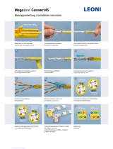
Assembly
Installation
1 Fasten the patch panel (D) through the four fastening holes (A) to the
cabinet.
Grounding
2 For grounding of the patch panel at the cabinet, respectively, at the
housing use the enclosed grounding set.
3 Mount the threaded bolt (E) necessarily before connecting
the wires and with opened strain relief and shielding clamp
on the left or right side of the patch panel!
4 Connect the enclosed grounding of the housing with the enclosed
Schutzleiter normgerecht.
Strain Relief and Shielding Contact
5 Shorten and prepare the cables according to the
recommendations (see next page ).
6 Loosen the fastening screws (F) of the secured
strain relief and shielding clamp for the cables.
7 Place the prepared cable with the cable jacket
to the dead stop of the shielding area, so that
the wire braid lies under the shielding area of the
clamp.
8 Put the strain relief and shielding clamp back
on and fasten the screw until the cable is firmly
secured.
Connection of Wires
9 Connect the wires according to the predetermined assignment card
(see next page).
Do not pull the single wires too firmly.
Maintain the twist of a pair as far as possible!
When connecting the wires, use the same color code for
the patch panel and jack!
10 Use the insertion tool to push the wires in the ter-
minal (the wires will be cut off at the same time).
11 In order to prevent short-circuits, remove the cut
off ends from the slide-in unit.
12 Close the patch panel with the cover plate and
fasten the cover plate (D).
13 Fasten the patch panel through the four fastening
holes (A) to the cabinet.
Sicherheitshinweise
Bitte achten Sie für eine störungsfreie Funktion bei der Auswahl des
Patchkabels auf eine normgerechte Ausführung der Stecker (gemäß
IEC 60603-7-x).
Geräteübersicht
A Befestigungslöcher
B Patchpanel
C Zugentlastungsschelle
mit Schirmkontakt
D Deckel
Installation
Montage
1 Befestigen Sie das Patchpanel (D) an den vier seitlichen Montage-
löchern (A) im Verteilerschrank.
Erdung
2 Zur Erdung des Patchpanels am Verteilerschrank bzw. am Gehäuse
(B) verwenden Sie das beiligende Erdungsset.
3 Montieren Sie den Gewindebolzen (E) unbedingt vor dem
An legen der Adern bei geöffneter Zugentlastungsschelle
links oder rechts am Patchpanel!
4 Verbinden Sie die Gehäuseerdung mit dem beigefügten Schutzleiter
normgerecht.
Zugentlastung und Schirmanschluss
5 Kürzen Sie die Kabel und bereiten diese gemäß
den Hinweisen (siehe folgende Seite) vor.
6 Lösen Sie die Zugentlastungsschraube (F) der
unverlierbaren Zugentlastungsschelle mit Schirm-
kontakt für die einzulegenden Anschlüsse.
7 Legen Sie das vorbereitete Kabelende mit dem
Kunststoffmantel bis zum Anschlag des Schirmbe-
reichs ein, so dass das Geflecht unter dem Schirm-
abgriff liegt.
8 Setzen Sie nun die Zugentlastungsschelle wieder
auf und schrauben Sie sie an, bis das Kabel fest-
sitzt.
Adern anlegen
9 Legen Sie die Adern gemäß vorgegebener Belegungskarte auf (siehe
Farbcode auf der nächsten Seite).
Ziehen Sie die Einzeladern beim Auflegen nicht zu straff.
Erhalten Sie die Verdrillung der Paare sowie die Schirmfo-
lie so lang wie möglich (bis zur Klemme)!
Beachten Sie die gleiche Belegung nach Farbcode im
Patchpanel und an der Anschlussdose/dem Modul!
10 Drücken Sie die Adern mit dem LSA-Anlegewerk-
zeug in die Klemmen (Adern werden gleichzeitig
gekürzt).
11 Entfernen Sie die abgeschnittenen Enden um
Kurzschlüsse zu vermeiden.
12 Schliessen Sie das Patchpanel mit Aufsetzten und
rückseitigem Verschrauben des Deckels (D).
13 Befestigen Sie das Patchpanel an den seitlichen
Befestigungs löchern (A) im Verteilerschrank.
Technical Support
+ 49 23 5 5 82-111
technical.support@rutenbeck.de
Commercial Support
+49 2355 82-137
commercial.support@rutenbeck.de
DC
C FE
A B

Klagebach 33
58579 Schalksmühle
Telefon +49-(0) 23 55-82-0
Telefax +49-(0) 23 55-82-105
www.rutenbeck.de
mail@rutenbeck.de
Farbcode (andere Farbkennzeichnungen möglich)
Kabelvorbereitung
Kabel mit Geflechtschirm/Kabeldurchmesser > 6 mm
Isolieren Sie den Kunststoffmantel ca. 70 mm ab. Schieben
Sie das Schirmgeflecht zurück und schneiden Sie es rund-
herum so ab, dass ca. 10 mm aus dem Kunststoffmantel
heraus ragen. Kürzen Sie die Schirmfolie und transparente
Polyesterfolie, so vorhanden, auf dieselbe Länge.
Beilaufdraht
Führen Sie den Beilaufdraht bei allen Kabeln bis zum
Kunststoffmantel zurück, wickeln ihn um das Geflecht und
klemmen ihn unter der Schelle fest.
Kabel mit Geflechtschirm/Kabeldurchmesser < 6 mm
Bei dünneren Kabeln (unter 6 mm Ø) isolieren Sie den
Kunst stoffmantel ca. 70 mm ab. Schieben Sie das
Geflecht über den Mantel zurück und kürzen es auf
14 mm.
Kabel mit Folienschirm
Isolieren Sie den Kunststoffmantel ca. 70 mm ab. Schnei-
den Sie Schirm- und Kunststofffolie so ab, dass ca. 10
mm aus dem Kunststoffmantel herausragen.
Den Beilaufdraht handhaben Sie wie beim Geflechtschirm.
Wichtiger Hinweis
Die Anschlusskomponenten ab Category 6 sind elektrisch und mecha-
nisch hoch entwickelte Stecksysteme für Übertragungsbandbreiten bis
500 MHz. Sie erfüllen die aktuellen Normen für die Bauform sowie die
Übertragungstechnik und die entsprechenden internationalen Festlegun-
gen in vollem Umfang. Um die Leistungsfähigkeit im Praxiseinsatz garantie-
ren zu können, sind auch die gleichen Anforderungen an die eingesetzten
Stecker/Patchkabel zu stellen! Verwenden Sie deshalb ausschließlich
Patchkabel mit Steckern, die gemäß Herstellerangaben den gültigen EN/
IEC-Normen entsprechen!
Bei der Vielfalt der Hersteller im Markt und unterschiedlichen Qualitäts-
lagen ist die erforderliche Normkonformität leider nicht bei allen Produkten
selbstverständlich! Vermeiden Sie auch unnötige, mechanische Belastun-
gen der Buchsen beim Stecken oder Ziehen des Patchkabels durch Zug-
oder Druckbelastung des Steckers oder durch Verkanten. Dies gilt für die
messtechnische Überprüfung, vor allem bei herstellerspezifischen Perma-
nent-Link-Adaptern, wie für den Alltagsbetrieb. Ein hochwertiges Hochfre-
quenzstecksystem sollte auch mit der gebotenen Sorgfalt bedient werden.
Bei Verwendung nicht normgerechter Anschlusskomponenten müssen wir
von einer Anerkennung des Mängelrechts oder anderen Garantiezusagen
unseres Hauses Abstand nehmen.
Bitte weisen Sie auch den Endnutzer auf diesen Sachverhalt hin.
Installation Installation
Color code (other color codes possible
Cable Preparation
Cable with Wire Braid/Cable Ø > 6 mm
Strip approx. 70 mm of the plastic outer sheath. Push the
wire braid back and cut it approx. 10 mm so that the plas-
tic outer sheath stand out.
Shorten the wire foil and the transparent polyester foil, if
provided, to the same length.
Supplementary Wire
Wind the supplementary wire of all cables to the plastic
outer sheath, round the wire braid and place it under the
cable clamp.
Cable with Wire Braid/Cable Ø < 6 mm
For thin cables (under 6 mm Ø) strip approx. 70 mm of the
plastic outer sheath. Push the braid back over the sheath
and cut it to 14 mm.
Cable with Wire Foil
Strip approx. 70 mm of the plastic outer sheath (see scale
below). Cut the wire- and plastic foil, approx. 10 mm, so
that the plastic outer sheath stands out.
Handle the supplementary wire as the wire braid.
Important Note!
The connecting hardware starting from Category 6 is a highly sophisticat-
ed electrical and mechanical connection system for transmission band
widths up to 500 MHz. They fulfil the current standards for the design as
well as the transmission technique and the corresponding international
directives to its entirety. In order to guarantee the high performance during
operation, the connectors and patch cables used must also meet these
requirements. Only use patch cables with connectors that correspond to
the valid EN/IEC standards.
Due to the multiplicity of manufacturers along with various quality levels
offered on the market at present, there is no guarantee that all products
fulfil the required standard conformity. Avoid unnecessary, mechanical
stress of the outlets caused by pull or pressure stress of the connec-
tor when inserting/removing patch cables or tilting. This also applies for
the link testing, especially when using manufacturer-specific Perma-
nent-Link-adapters as well as for daily use. A top-quality high frequency
connection system should always be operated with the required caution.
When using non-standard connecting hardware (i. e. patch cables, con-
nectors) we will not accept any warranty claims.
Please, inform the end-user about this issue.
© Wilhelm Rutenbeck GmbH & Co. KG · Technische Änderungen vorbehalten/Subjected to technical changes · 293 600 · 104513xx · Rut038 · Stand/Status 08.18
Anschlussklemme/
Terminalblock
Code gemäß
acc. to TIA/EIA-568-B.2
1 2 3 4 5 6 7 8
T568A
weiß/grün grün weiß/orange blau weiß/blau orange weiß/braun braun
white/green green white/orange blue white/blue orange white/brown brown
T568B
weiß/orange orange weiß/grün blau weiß/blau grün weiß/braun braun
white/orange orange white/green blue white/blue green white/brown brown
70 mm
10 mm
70 mm
70 mm
14 mm
< 6 mm
70 mm
70 mm
10 mm
1/2