
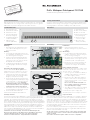
PoE+ Midspan-Patchpanel 19“/1HE
Installationsanleitung/Installation Instructions
Safety Instructions
In order to achieve a trouble-free performance, please pay attention to a
standard conform design of the plug (according to IEC 60603-7-x) when
selecting a patch cord and the suitability of the cable for PoE+.
Overview
A Fastening holes
B RJ45 socket Data In
C RJ45 socket PoE
D Connection threaded
bolt (earthing set)
E Strain relief lug for
connection cable
F DC connection-
clamp (removable)
Assembly
Installation
1 Fasten the patch panel to the four
lateral mounting holes (A) in the network
cabinet.
Grounding
2 For grounding of the patch panel at the
cabinet, respectively, at the housing use
the enclosed grounding set.
3 Mount the enclosed threaded bolt at the
marked positions on the right or left side
on the base plate of the patch panel.
4 Connect the enclosed grounding of the
housing with the enclosed protective
conductor according to the standards.
Power supply connection
An additional, external power supply unit is
required to operate up to three PoE+ end
devices (item no. 23510306).
5 Select (e.g. in the distribution cabinet) a
suitable location. On this consider the
two cable lengths (I and H).
6 Connect the two cables (G) equipped
with wire end sleeves to the plug-in ter-
minals (F) marked with +/- in accordance
with the standards.
Each ‘used’ module/board (with 3 x
two sockets) requires the connection
of a separate power supply.
7 The cable should be relieved of strain by
using cable ties on the base plate (E).
8 Connect the power supply unit.
The patch panel is now ready for operation.
Important Note!
The connecting hardware starting from Category 6 is a highly sophisticat-
ed electrical and mechanical connection system for transmission band
widths up to 500 MHz. They fulfil the current standards for the design as
well as the transmission technique and the corresponding international
directives to its entirety. In order to guarantee the high performance during
operation, the connectors and patch cables used must also meet these
requirements. Only use patch cables with connectors that correspond to
the valid EN/IEC standards.
Due to the multiplicity of manufacturers along with various quality levels
offered on the market at present, there is no guarantee that all products
fulfil the required standard conformity.
Avoid unnecessary, mechanical stress of the outlets caused by pull
or pressure stress of the connector when inserting/removing patch
cables or tilting.
Also make sure that the patch cables are PoE+ compatible.
Sicherheitshinweise
Bitte achten Sie für eine störungsfreie Funktion bei der Auswahl des
Patchkabels auf eine normgerechte Ausführung der Stecker (gemäß
IEC 60603-7-x) und auf Tauglichkeit des Kabel auf PoE+.
Geräteübersicht
A Befestigungslöcher
B RJ45 Buchse Data In
C RJ45 Buchse PoE
D Anschluss Gewinde-
bolzen (Erdungsset)
E Zugentlastungs lasche
für Anschlusskabel
F DC-Anschluss-
klemme (abziehbar)
Installation
Montage
1 Befestigen Sie das Patchpanel an den
vier seitlichen Montagelöchern (A) im
Netzwerkschrank.
Erdung
2 Zur Erdung des Patchpanels am Vertei-
lerschrank bzw. am Gehäuse verwenden
Sie das beiligende Erdungsset.
3 Montieren Sie den beiligenden Gewin-
debolzen an einer der gekennzeichne-
ten Stellen rechts oder links (D) auf der
Grundplatte des Patchpanels.
4 Verbinden Sie die Gehäuseerdung mit
dem beigefügten Schutzleiter normge-
recht.
Anschluss der Stromversorgung
Für den Betrieb von bis zu je drei PoE+
Endgeräten ist ein zusätzliches, externes
Netzteil erforderlich (Art.-Nr. 23510306).
5 Wählen Sie im Netzwerkschrank einen
geeigneten Platz, der die beiden Kabel-
längen (I und H) berücksichtigt.
6 Schließen Sie die beiden mit Adernend-
hülsen ausgestatteten Kabel (G) normge-
recht an den mit +/– gekennzeichneten
Steckklemmen (F) an. Je ‚genutzter‘
Baugruppe/Platine (mit 3 x zwei Buch-
sen) ist der Anschluss einer separaten
Spannungsversorgung erforderlich.
7 Das Kabel sollte z. B. per Kabelbinder an
der Grundplatte (E) zugentlastet werden.
8 Schließen Sie das Netzteil an.
Damit ist das Patchpanel betriebsbereit.
Wichtiger Hinweis
Die Anschlusskomponenten ab Category6 sind elektrisch und mecha-
nisch hoch entwickelte Stecksysteme für Übertragungsbandbreiten bis
500 MHz. Sie erfüllen die aktuellen Normen für die Bauform sowie die
Übertragungstechnik und die entsprechenden internationalen Festlegun-
gen in vollem Umfang. Um die Leistungsfähigkeit im Praxiseinsatz garantie-
ren zu können, sind auch die gleichen Anforderungen an die eingesetzten
Stecker/Patchkabel zu stellen! Verwenden Sie deshalb ausschließlich
Patchkabel mit Steckern, die gemäß Herstellerangaben den gültigen EN/
IEC-Normen entsprechen! Bei der Vielfalt der Hersteller im Markt und
unterschiedlichen Qualitäts lagen ist die erforderliche Normkonformität lei-
der nicht bei allen Produkten selbstverständlich!
Vermeiden Sie auch unnötige, mechanische Belastungen der
Buchsen beim Stecken oder Ziehen des Patchkabels durch Zug-
oder Druckbelastung des Steckers oder durch Verkanten.
Achten Sie zudem auf PoE+ Tauglichkeit der Patchkabel.
Technical Support
+49 23 5 5 82-111
Commercial Support
+49 2355 82-137
A AB C
1
D
2
E
F
G
H
I
3

Klagebach 33
58579 Schalksmühle
Telefon +49-(0) 23 55-82-0
Telefax +49-(0) 23 55-82-105
www.rutenbeck.de
Wir, die Wilhelm Rutenbeck GmbH & Co. KG erklären in unserer
alleinigen Verantwortung, dass sich dieses Gerät in Übereinstim-
mung mit den grundlegenden Anforderungen und relevanten Vor-
schriften der zutreffenden EU-Richtlinien (2014/30/EU, 2014/35/
EU, 2011/65/EU) befindet. Die vollständige CE-Konformitätserklä-
rung finden Sie unter www.rutenbeck.de im Download-Bereich.
Entsorgung
Das nebenstehende Symbol weist auf die getrennte Sammlung von
Elektro- und Elektronikgeräten hin. Dieses Gerät sowie alle im Lie-
ferumfang enthaltenen Elektronikteile dürfen gemäß europäischer
Richtlinien und deutschem Elektro- und Elektronikgesetz nicht über
den Hausmüll entsorgt werden.
Bringen Sie dieses Gerät nach Ende seiner Nutzung zu einem
zuständigen Sammelsystem für elektrische und elektronische Alt-
geräte.
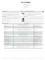
Technische Daten
CE-Erklärung CE - Declaration of confirmity
We, Wilhelm Rutenbeck GmbH & Co. KG, declare under our sole
responsibility that this device is in conformity with the essential
requirements and the relevant regulations of the applicable EU-
directives (2014/30/EU, 2014/35/EU, 2011/65/EU).
The complete Declaration of Conformity is available in the Down-
load Section at www.rutenbeck.com
Disposal
The adjacent symbol indicates separate waste collection for elec-
trical and electronic devices. In accordance with EU-directives,
all electrical and electronic devices with this symbol must be dis-
posed in the corresponding separate waste collections and not in
the domestic waste.
This device as well as all the electronic parts included in the delivery
may not be disposed in the regular household waste but must be
brought to a competent collection site after end of its use.
Technical Data
© Wilhelm Rutenbeck GmbH & Co. KG · Technische Änderungen vorbehalten / Subjected to technical changes · 293 823 · Panel: 23510305 · Spannungsversorgung: 23510306 · Rut090 · Stand / Status 11.20
PoE+ Midspan-Patchpanel 19“/1HE
Schutzart IP20 gemäß / according to DIN EN 60529 Protection Class
Betriebstemperatur -5 °C bis / to 40 °C Operating temperature
Anschlüsse
12 x RJ 45 Buchsen für Dateneingang / sockets for data input
12 x RJ 45 Buchsen mit PoE+ Ausgang / sockets with PoE+ output
2x 230 V Steckklemmen / plug-in terminals
4 x zweipolige Steckklemmen (abziehbar) für DC Anschluss
4 x two-pole plug-in terminals (removable) for DC connection
Connections
PoE+ gemäß / according to IEEE 802.3at PoE+
Datenrate 1000 Mbit/s Data rate
PoE+ Spannungsversorgung
Schutzart IP20 gemäß / according to DIN EN 60529 Protection Class
Betriebstemperatur -5 °C bis / to 40 °C Operating temperature
Nennbetriebsspannung 100 – 240 V ~ / 50 – 60 Hz Nominal operating voltage
Leistungsaufnahme 1100 – 470 mA Power consumption
Ausgangsspannung 52–57 V DC Output voltage
Ausgangsleistung 90 W Output power
Kurzschlussfestigkeit ja / yes Short-circuit protection
Leerlauffestigkeit ja / yes Idle resistance
PoE+ Ünterstützung maximal 3 PoE+ Geräte (je 30 W) / maximal 3 PoE+ devices (each 30 W) PoE+ support
Anschlüsse
Spannungsanschluss mittels 3-poligem Schukostecker/-leitung (150 cm)
Voltage connection by means of 3-pole shock-proof plug/cable (150 cm)
Spannungsausgang: DC-Anschlussleitung (200 cm)
Voltage output: DC connection cable (200 cm)
Connections
-
 1
1
-
 2
2


Rutenbeck 23510305 - PoE+ Midspan-Patchpanel 19“/1HE Benutzerhandbuch
- Typ
- Benutzerhandbuch
- Dieses Handbuch ist auch geeignet für
in anderen Sprachen
Verwandte Papiere
-
Rutenbeck SK Ap Benutzerhandbuch
-
-
-
-
-
-
-
-
-