SICK LFP Inox Compact Bedienungsanleitung
- Typ
- Bedienungsanleitung

LFP Inox Compact
(ohne Sondenstab)
Gilt für LFP0025-C1NMB,
LFP0025-D1NMB, LFP0025-
C2NMB und LFP0025-D2NMB.
LFP0025 - Technical Information
LFP Inox Compact
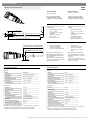
M5
min. 10 mm (0.39")
Länge Sondenstab / Probe length
7...8 mm
(
0.27... 0.31")
• Gesamt-Sondenlänge:
200 mm … 4.000 mm
• Gesamt-Sondenlänge =
15 mm + Länge Sondenstab
Die Gesamt-Sondenlänge ist im
Menü EXPRT-Length einzustellen.
Das Menü EXPRT-Length ist pass-
wortgeschützt.
Wir empfehlen die Gewindeverbin-
dung mit Schraubensicherungslack
(z.B. Loctite) zu sichern.
100 mm (3.94") ... 4000 mm (157.48")
15
(0.59")
Länge Sondenstab / probe length
Gesamt Sondenlänge / total probe length
• Overall length:
200 mm ... 4,000 mm
• Overall probe length =
15 mm (0.59”) + Probe
length
Enter the overall probe length
in the EXPRT-Length menu. The
EXPRT-Length menu is password
protected.
To secure the threaded connec-
tion, we recommend to use thread
locker (e.g. Loctite).
LFP Inox Compact
(without mono probe)
Applies to LFP0025-C1NMB,
LFP0025-D1NMB, LFP0025-
C2NMB and LFP0025-D2NMB.
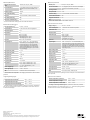
Merkmale
Medium Flüssigkeiten
Erfassungsart Grenzstand, kontinuierlich
Sondenlänge 200 mm ... 4.000 mm
Einstellbarer Messbereich 95 mm ... 6.005 mm
Prozessdruck –1 bar ... +16 bar
Prozesstemperatur –20°C ... +150°C
Performance
Genauigkeit
1)
4)
± 5 mm
Reproduzierbarkeit
1)
≤2mm
Auösung < 2 mm
Ansprechzeit
2)
< 400 ms
Dielektrizitätskonstante ≥5beiMonosonde
≥1,8mitKoaxialrohr
Leitfähigkeit KeineEinschränkung
Maximale Füllstandsänderung
3)
500 mm/s
Inaktiver Bereich am Sondenende
1)
10 mm
1)
Unter Referenzbedingungen mit Wasser.
2)
AbhängigvomMessmodus(High-Speed<400ms,HighAccuracy<2800ms)
3)
AbhängigvonderParametrierung(MaxCol-Maximumchangeoflevel)
4)
DetailsimGenauigkeitsdiagramm,BetriebsanleitungLFP8014485.
Technische Daten
Technical data
Features
Medium Fluids
Measurement Switch, continuous
Probe length 200 mm ... 4,000 mm
Adjustable measuring range 95 mm ... 6,005 mm
Process pressure –1 bar ... +16 bar
Process temperature –20°C ... +150°C
Performance
Accuracy
1)
4)
±5 mm
Reproducibility
1)
≤ 2 mm
Resolution < 2 mm
Response time
2)
< 400 ms
Dielectric constant ≥5formono-probe
≥1.8withcoaxialtube
Conductivity No limitation
Maximum level change
3)
500 mm/s
Inactive area at end of probe
1)
10 mm
1)
With water under reference conditions.
2)
Dependentonmeasuringmode(highspeed<400ms,highaccuracy<2,800ms)
3)
Dependentonconguration(maxCol-Maximumchangeoflevel)
4)
Detailsinaccuracydiagram,operatinginstructionsLFP8014485.
8019645/2016-03-09∙Printed in Germany∙09-03-2016∙03/16∙ Subject to change without notice∙SICKAG∙Waldkirch∙ Germany∙www.sick.com
AtLFPInoxamonoprobecanbe
adapted.
• Mono probe diameter:
7mm...8mm(0.27”…
0.31”)
• Female thread at the mono
probe: M5
• Female thread length:
min. 10 mm (0.39”)
• Material: Stainless steel
BeiLFPInoxlässtsicheinSonden-
stab adaptieren.
• Sondenstabdurchmesser:
7mm…8mm
• Innengewinde am Sonden-
stab: M5
• Länge Innengewinde:
min. 10 mm
• Werkstoff: Edelstahl
D
EN

Mechanik/Werkstoffe
Medienberührende Werk-
stoffe
1.4404(Ra≤0,8µm),PEEK
Prozessanschluss G 3/4 (Hygienische Prozessanschlüsse mit
Adapter für G 3/4, siehe Zubehör), 3/4“
NPT
Gehäusematerial 1.4305
Max. Sondenbelastung 6 Nm
Schutzart IP67:EN60529,IP69K:EN40050
Koaxialkabelisolierung FEP
Elektrische Kabelisolierung
1)
PVC
1)
Version mit elektrischer Leitung anstatt eines M12 Anschlusses.
Elektrische Anschlusswerte
Versorgungsspannung
1) 2)
12 V DC ... 30 V DC
Stromaufnahme ≤100mAbei24VohneAusgangslast
Initialisierungszeit ≤5s
Schutzklasse III
Anschlussart M12x1,5-polig
M12x1,8-polig
Kabelausgang10m,5-pol.
Kabelausgang10m,8-pol.
Hysterese Min. 3 mm, frei einstellbar
Ausgangssignal
1)
4 mA … 20 mA / 0 V … 10 V automatisch
umschaltbar je nach Ausgangslast 1 PNP-
Transistorausgang (Q1) und 1 PNP/NPN-
Transistorausgang (Q2) umschaltbar oder
1 PNP-Transistorausgang (Q1) und 3 PNP/
NPN-Transistorausgang (Q2...Q4) umschalt-
bar (typabhängig)
Signalspannung HIGH Uv –2 V
Signalspannung LOW ≤2V
Ausgangsstrom < 100 mA
Induktive Last < 1 H
Kapazitive Last 100 nF
Temperaturdrift <0,1mm/K
Ausgangslast 4 mA … 20 mA < 500 Ohm bei Uv > 15 V;
4 mA … 20 mA < 350 Ohm bei Uv > 12 V;
0 V … 10 V > 750 Ohm bei Uv ≥ 14 V
Unterer Signalpegel 3,8mA...4mA
Oberer Signalpegel 20 mA ... 20,5 mA
EMV EN61326-1:2013,2004/108/EG
1)
Alle Anschlüsse sind verpolsicher. Alle Ausgänge sind überlast- und kurzschluss-
geschützt.
Umgebungsbedingungen
Umgebungstemperatur Betrieb
1)
–20°C ... +60°C
Umgebungstemperatur Lager –40°C...+80°C
Umgebungstemeratur Koaxialleitung –20°C ... +60°C
1)
Gemäß UL-Listing: Verschmutzungsgrad 3 (UL61010-1: 2012-05); Luftfeuchtig-
keit:80%beiTemperaturenbiszu31°C;Einsatzhöhe:max3.000mü.M.;nur
für Indoor-Anwendungen.
Mechanics/materials
Wetted parts 316L(Ra≤0.8µm),PEEK
Process connection G 3/4 (hygienic process connectors with adapter
for G 3/4, see accessories), 3/4" NPT
Housing material 303
Max. probe load 6 Nm
Enclosure rating IP67:EN60529,IP69K:EN40050
Coaxial cable insulation FEP
Electrical cable insula-
tion
1)
PVC
1)
Version with electrical cable instead of M12 connector.
Electrical connection values
Supply voltage
1) 2)
12 V DC ... 30 V DC
Power consumption ≤100mAat24Vwithoutoutputload
Initialization time ≤5s
Protection class III
Connection type M12x1(5-pin)
M12x1,8-pol.
Flying leads 10 m, 5-pol.
Flyingleads10m,8-pol.
Hysteresis Min. 3 mm, freely adjustable
Output signal
1)
4 mA ... 20 mA / 0 V ... 10 V automatically swit-
chable depending on output load 1 PNP transistor
output (Q1) and 1 PNP/NPN transistor output (Q2)
switchable, or 1 PNP transistor output (Q1) and 3
PNP/NPN transistor outputs (Q2 to Q4) switchable
(depending on type)
Signal voltage HIGH Uv –2 V
Signal voltage LOW ≤2V
Output current < 100 mA
Inductive load < 1 H
Capacitive load 100 nF
Temperature drift <0.1mm/K
Output load 4 mA ... 20 mA < 500 ohms at Uv > 15 V;
4 mA ... 20 mA < 350 ohms at Uv > 12 V;
0 V ... 10 V > 750 ohms at Uv ≥ 14 V
Lower signal level 3.8mA...4mA
Upper signal level 20 mA ... 20.5 mA
EMC EN61326-1:2013,2004/108/EC
1)
All connections are reverse polarity protected. All outputs are overload and short-
circuit protected.
Environmental conditions
Ambient temperature, operation
1)
–20°C ... +60°C
Ambient temperature, storage –40°C...+80°C
Ambient temperature, coaxial cable –20°C ... +60°C
1)
AccordingtoUL-Listing:Pollutiondegree3((UL61010-1:2012-05);maximum
relativehumidity80%fortemperaturesupto31°C;maximumoperatingaltitude
of 3,000 m above sea level; for indoor applications only.
SICKAG∙Fluidsensorik
Erwin-Sick-Str. 1
79183Waldkirch∙Germany∙www.sick.com
8019645/9-03-2016
Printed in Germany (HC)∙Alle Rechte vorbehalten∙Angegebene Produkteigenschaften und
technische Daten stellen keine Garantieerklärung dar. Subject to change without notice.
-
 1
1
-
 2
2


SICK LFP Inox Compact Bedienungsanleitung
- Typ
- Bedienungsanleitung
Verwandte Artikel
-
SICK LFP Inox Quickstart
-
-
-
-
-
-
-
-
-