
LFP Inox
8018147/ZNR0/2017-07-17 ∙ Printed in Germany (GW/KE) ∙ Subject to change without notice ∙ SICK AG ∙ Waldkirch ∙ Germany ∙ www.sick.com
8018147/ ZNR0/2017-07-17
Dieses Dokument gilt nur in Verbindungmit der zugrunde
liegenden Betriebsanleitung (SICK Art-Nr. 8014485) des
verwendeten LFP Inox. Die Betriebsanleitung können Sie
unter www.sick.com herunterladen.
Wartung/Rücksendung/Entsorgung
Sicherheitshinweise
■
Lesen Sie die Betriebsanleitung vor der Inbetriebnah-
me.
■
Dieser Quickstart gilt für Geräte ab Firmwareversion
V4.00.
■
Anschluss, Montage und Einstellung nur durch
Fachpersonal.
■
Der LFP ist kein Sicherheitsmodul gemäß EU-Maschi-
nenrichtlinie.
■
Beachten Sie die nationalen Sicherheits- und Unfall-
verhütungsvorschriften.
■
Reparaturen dürfen nur vom Hersteller durchgeführt
werden. Eingriffe und Änderungen am Gerät sind
unzulässig.
■
Verdrahtungsarbeiten, Öffnen und Schließen von
elektrischen Verbindungen nur im spannungs losen
Zustand durchführen.
■
Die abgestrahlte Energie unterschreitet die von
Telekommunikationseinrichtungen um ein Viel faches.
Nach dem aktuellen Stand der Wissenschaft kann der
Betrieb des Gerätes als gesundheitlich unbedenklich
eingestuft werden.
■
Unsachgemäßer oder nicht bestimmungsgemäßer
Gebrauch können zu Funkitonsstörungen in Ihrer
Applikation führen.
Quickstart
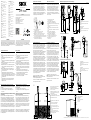
C
A
D
B
B
Koaxialsonde
Monosonde
coaxial tube
mono probe
Monosonde mit metallischen Behältern
Einbau im Stutzen:
D ≥ DN 25
Abstand Behälterwand/ Behälterboden:
A ≥ 50 mm;
B ≥ 10 mm
Abstand zu Behältereinbauten:
≥ 100mm
Unit with mono probe mounted in metal
tank
Installation in noozle: D
≥
DN25 (1“)
Distance tank wall/tank bottom:
A
≥
50 mm (1.97“); B
≥
10 mm (0.40“)
Distance to other tank ttings:
≥
100 mm
(3.94“)
Unit with coaxial tube for metal and non
metal tank
C = with a coaxial tube there are no
minimum distances to the tank wall or to
other tank ttings required
Koaxialrohr in metallischen und nichtme-
tallischen Behältern
C = Bei einer Koaxialsonde sind
keine Mindestabstände zur Behälterwand
und zu einbauten einzuhalten
D
B
Zentrieren
Center
D ≥ DN 40
Abstand zu Bypassboden/
Behälterboden
B ≥ 15 mm
Distance to bypass bottom/
tank bottom
B ≥ 15 mm
Der Sensor wird über eine fertig konfektio-
nierte Leitungsdose mit M12 x 1-Steckverbin-
der, 5-/8-polig angeschlossen. Leitungsdose
spannungsfrei auf den Sensor aufstecken und
festschrauben. Leitung gemäß ihrer Funktion
anschließen. Nach Anlegen der Versorgungsspan-
nung führt der Sensor einen Selbsttest durch – im
eingebauten Zustand ist nach abgeschlossenem
Selbsttest (< 5 s) der Sensor betriebsbereit – das
Display zeigt den aktuellen Messwert an.
Der LFP ist wartungsfrei. Wir empfehlen in regelmäßigen
Abständen:
■
die Sonde auf Verschmutzung zu überprüfen
■
die Verschraubungen und Steckverbindungen zu
überprüfen
Unbedenklichkeitserklärung (Kontaminationserklärung
im Servicefall)
Spülen bzw. säubern Sie ausgebaute Geräte vor der
Rücksendung, um unsere Mitarbeiter und die Umwelt
vor Gefährdung durch anhaftende Messstoffreste zu
schützen. Eine Überprüfung ausgefallener Geräte kann
nur erfolgen, wenn das vollständig ausgefüllte Rücksen-
deformular vorliegt. Eine solche Erklärung beinhaltet alle
Materialien, welche mit dem Gerät in Berührung kamen,
auch solche, die zu Testzwecken, zum Betrieb oder zur
Reinigung eingesetzt wurden. Das Rücksendeformular ist
über unsere Internet-Adresse (www.sick.com) verfügbar.
Entsorgen Sie Gerätekomponenten und Verpackungsma-
terialien entsprechend den einschlägigen landesspezi-
schen Abfallbehandlungs- und Entsorgungsvorschriften
des Anliefergebietes.
Safety Notes
■
Read the operating instructions prior to commission-
ing.
■
This quickstart applies to devices with rmware
version V4.00.
■
Connection, mounting, and setting may only be
performed by trained specialists.
■
The LFP is not a safety module according to the EU
Machinery Directive.
■
Observe national safety and work safety regulations.
■
Repairs may only be carried out by the manufacturer.
Altering or tampering with the device is not permitted.
■
Wiring work and the opening and closing of electrical
connections may only be carried out when the power
is switched off.
■
The radiated power is far lower than that from
telecommunication equipment. According to current
scientic knowledge, operating the device is not
considered to pose any health risks.
■
Incorrect handling or improper use can lead to
malfunctions in your application.
This document is only valid in conjunction with the origi-
nal operating instructions (SICK part no. 8014485) for
the corresponding LFP Inox. You can obtain the operating
instructions at www.sick.com.
The sensor is connected using a pre-assembled
cable socket with 1 x M12 plug connector (5-pin
/ 8-pin). With the power switched off, plug the
cable socket into the sensor and screw it tight.
Connect the cable according to its function.
After the supply voltage has been applied, the
sensor carries out a self-test. Once installed, the
sensor is ready for operation on completion of
the self-test (< 5 s). The display shows the current
measured value.
Maintenance/Returns/Disposal
The LFP is maintenance-free. We recommend doing the
following regularly:
■
checking the probe for contamination
■
checking the screw connections and plug-in connec-
tions
Declaration of no objection (contamination declaration
in the event of service work)
Rinse off or clean removed devices before returning
them in order to protect our employees and the environ-
ment from dangers posed by residue from measured
materials. Faulty devices can only be examined when
accompanied by a completed return form. A declaration
of this type includes information about all materials
which have come into contact with the device, including
those which were used for testing purposes, operation,
or cleaning. The return form is available at our internet
site (www.sick.com).
Dispose of device components and packaging materials
in compliance with applicable country-specic waste
treatment and disposal regulations of the region of use.
ENGLISH
DEUTSCH
123
(4.84)
22
(0.87)
L
IA
M
IAE
36
(1.42)
54
(
2.13)
38
(1.50)
M12x1
20
(0.78)
145
(5.71)
22
(0.87)
15
(0.59)
L
G 3/4 A
3/4" NPT
IAE
IA
M
32
(1.26)
G 3/4 A
3/4" NPT
7
(
0.28)
77
(3.03)
Australia
Phone +61 3 9457 0600
1800 334 802 – tollfree
Austria
Phone +43 (0)22 36 62 28 8-0
Belgium/Luxembourg
Phone +32 (0)2 466 55 66
Brazil
Phone +55 11 3215-4900
Canada
Phone +1 905 771 14 44
Czech Republic
Phone +420 2 57 91 18 50
Chile
Phone +56 2 2274 7430
China
Phone +86 4000 121 000
Denmark
Phone +45 45 82 64 00
Finland
Phone +358-9-2515 800
France
Phone +33 1 64 62 35 00
Gemany
Phone +49 211 5301-301
Great Britain
Phone +44 (0)1727 831121
Hong Kong
Phone +852 2153 6300
Hungary
Phone +36 1 371 2680
India
Phone +91–22–4033 8333
Israel
Phone +972-4-6881000
Italy
Phone +39 02 27 43 41
Japan
Phone +81 (0)3 5309 2112
Malaysia
Phone +603 808070425
Netherlands
Phone +31 (0)30 229 25 44
New Zealand
Phone +64 9 415 0459
0800 222 278 – tollfree
Phone +1(952) 941-6780
1 800-325-7425 – tollfree
Norway
Phone +47 67 81 50 00
Poland
Phone +48 22 837 40 50
Romania
Phone +40 356 171 120
Russia
Phone +7-495-775-05-30
Singapore
Phone +65 6744 3732
Slovakia
Phone +421 482 901201
Slovenia
Phone +386 (0)1-47 69 990
South Africa
Phone +27 11 472 3733
South Korea
Phone +82 2 786 6321
Spain
Phone +34 93 480 31 00
Sweden
Phone +46 10 110 10 00
Switzerland
Phone +41 41 619 29 39
Taiwan
Phone +886 2 2375-6288
Thailand
Phone +66 2645 0009
Turkey
Phone +90 (216) 528 50 00
United Arab Emirates
Phone +971 (0) 4 88 65 878
USA/Mexico
Phone +1(952) 941-6780
1 (800) 325-7425 – tollfree
Vietnam
Phone +84 8 62920204
SICK AG • Fluid Sensors
Erwin-Sick-Straße 1
D-79183 Waldkirch • www.sick.com
8018147/ZNR0/2017-07-17
Printed in Germany (2017-07)
All rights reserved
Subject to change without notice
1
Der LFP wird mittels seines Prozessanschlusses
senkrecht von oben in den Behälter oder Bypass
montiert. Der Füllstandsensor LFP verfügt über
einen G ¾ oder ¾“ NPT Gewindeanschluss.
Ein minimaler Stutzendurchmesser gemäß nachfol-
gender Grak 1 ist dabei einzuhalten.
Der LFP ist so einzubauen, dass nach der Montage
genügend Abstand zu anderen Tankeinbauten
(z. B. Zulaufrohre, andere Messgeräte), der
Behälterwand oder zum Behälterboden besteht.
Mindestabstände sind ebenfalls in der Grak 1
beschrieben. Der LFP kann auch in einem metalli-
schen Tauchrohr oder Bypass eingesetzt werden.
Die Einbaubedingungen sind in der Grak 2
dargestellt. Es ist darauf zu achten, dass zwischen
Messgerät LFP und dem Tank/Bypass eine gute
metallische Verbindung besteht. Beim Betrieb des
Sensors dürfen die Grenzen für die Umgebungs-
temperatur nicht unter- oder überschritten werden.
Das Einisolieren des Sensorgehäuses bei Tanks
mit heißen Medien ist nicht erlaubt. Der Einbauort
ist so zu wählen, dass der Sensor nicht direkt dem
Befüllstrom ausgesetzt ist. Das Sensorgehäuse ist
um 360° drehbar und somit kann der Kabelab-
gang frei eingestellt werden.
Einbau in einen Behälter siehe Grak 1.
Hinweis: Die Abstände sind die Gleichen für den
Sensor mit abgesetzter Elektronik.
Einbau in ein metallisches Tauchrohr oder metal-
lischen Bypass siehe Grak 2.
Einbaubedigungen Installation conditions
The LFP is mounted vertically from above into the
container or bypass, using its process connection.
The LFP level sensor has a G ¾ or ¾" NPT thread-
ed connection.
A minimum nozzle diameter in accordance with
Diagram 1 below must be observed.
The LFP is to be installed in such a way that, after
it has been mounted, there is a sufcient distance
between it and the other tank components (e.g.,
supply pipes, other measuring devices) as well
as the sides or bottom of the container. These
minimum distances are also specied in Diagram
1. The LFP can also be used in a metal immer-
sion tube or bypass. The installation conditions are
shown in Diagram 2. Ensure that there is a good
metallic connection between the LFP measuring
device and the tank/bypass. When operating the
sensor, ensure that the ambient temperature
is not above or below the limits. Insulating the
sensor housing is not permitted for tanks with hot
media. When positioning the device, ensure that
the sensor is not directly exposed to the lling ow.
The sensor housing has 360° rotation, allowing
the cable outlet to be adjusted freely.
Installation in a container see picture 1.
Note: The LFP with remote amplier has the same
distances requirements.
Installation in a metal immersion tube or metal
bypass see picture 2.
L
min. R50
(min.1.97)
22
(0.87)
142
(5.59)
IAE
IA
M
6
(0.24)
40
(
1.58)
G 3/4 A
3/4" NPT
7
(
0.28)
C
36
(1.42)
36
(1.42)
132.4
(5.21)
14
(0.55)
6.5
(
0.26)
94.4
(3.72)
40
(1.58)
73
(2.87)
38
(1.50)
M12x1
54
(
2.13)
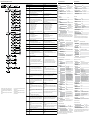
C: Leitungslänge
IA: Inaktiver Bereich am Prozessanschluss
20 mm / 40 mm
IAE: Inaktiver Bereich am Sondendende
10 mm
C: Cable length
IA: Inactive area process connection 20 mm
(0.79'') / 40 mm (1.58'')
IAE: Inactive area at probe end 10 mm
(0.39'')
M: Messbereich
L: Sondenlänge
IA: Inaktiver Bereich am Prozessanschluss
25 mm
IAE: Inaktiver Bereich am Sondendende
10 mm
M: Measuring range
L: Probe length
IA: Inactive area process connection 25 mm
(0.79'')
IAE: Inactive area at probe end 10 mm
(0.39'')
Monosonde/monoprobe
mit Koxialrohr/with coaxial probe
mit abgesetzter Elektronik /with remote amplier
Alle Maße in mm
All dimensions in mm (inch )
Maßzeichnungen/Dimensional drawings
Elektrischer Anschluss Electrical connection
1 L
+
: Versorgungsspannung, braun
L
+
: Supply voltage, brown
2 Q
A
: Analog Strom-/Spannungsausgang, weiß
Q
A
: Analog current-/voltage output, white
3 M: Masse, OUT- für Strom-/Spannungsausgang, blau
M: Ground, OUT- for current-/voltage output, blue
4 C/Q
1
: Schaltausgang 1, PNP/IO-Link-Kommunikation, schwarz
C/Q
1
: Switching output 1, PNP/IO-Link communication, black
5 Q
2
: Schaltausgang 2, PNP/NPN, grau
Q
2
: Switching output 2, PNP/NPN, grey
1 L
+
: Versorgungsspannung, weiß
L
+
: Supply voltage, white
2 Q
2
: Schaltausgang 2, PNP/NPN, braun
Q
2
: Switching output 2, PNP/NPN, brown
3 M: Masse, Bezugsmasse für Strom-/Spannungsausgang,
grün
M : G r o u n d , r e f e r e n c e p o t e n t i a l f o r c u r r e n t / v o l t a g e
output, green
4 C/Q
1
: Schaltausgang 1, PNP/IO-Link-Kommunikation,
gelb
C/Q
1
: Switching output 1, PNP/IO-Link communication,
yellow
5 Q
3
: Schaltausgang 3, PNP/NPN, grau
Q
3
: Switching output 3, PNP/NPN, gray
6 Q
4
: Schaltausgang 4, PNP/NPN, rosa
Q
4
: Switching output 4, PNP/NPN, rose
7 Q
A
: Analog Strom-/Spannungsausgang, blau
Q
A
: Analog current/voltage output, blue
8 Keine Funktion, rot
No function, red
2
L
22
(0.87)
123
(4.84)
IA
IAE
M
36
(1.42)
G 3/4 A
3/4" NPT
7
(
0.28)
77
(3.03)
43
(1.69)
115
(4.53)
ca. 10000
(ca. 393.7)
54
(
2.13)
M12
mit Leitungsverschraubung /with cable
- www.sick.com/LFP_Inox

Menü-Übersicht/Menu overview
Parameter Beschreibung Description
AutCal
Aktivierung der Behälterkalibrierung Activation of the container calibration
QxMENU
Menü Schaltausgang 1, 2, 3 oder 4 Menu switching output 1, 2, 3 or 4
SPx
Schaltpunkt Schaltausgang 1, 2, 3 oder 4 (SPx > RPx)
Hinweis: Erscheint nicht mehr, wenn der Schaltausgang im Menü
OUx auf Error oder Fenster gestellt ist.
Switching point, switching output 1, 2, 3 or 4 (SPx > RPx)
RPx
Rückschaltpunkt Schaltausgang 1, 2, 3 oder 4
Hinweis: Erscheint nicht mehr, wenn der Schaltausgang im Menü
OU2/3/4 auf Error oder Fenster gestellt ist.
Reset point, switching output 1, 2, 3 or 4
Note: This stops appearing when the switching output is set to Error
or Window in the OU2 menu.
FHx
FLx
Fensterfunktion obere Schwelle (high) Schaltausgang 1/2/3/4 (FHx
> FLx)
Fensterfunktion untere Schwelle (low) Schaltausgang 1/2/3/4
Hinweis: Erscheint nicht mehr, wenn der Schaltausgang im Menü
OU2/3/4 auf Error oder Hysterese gestellt.
Upper threshold (high) window function, switching output 1/2/3/4
(FHx > FLx)
Lower threshold (low) window function, switching output 1/2/3/4
Note: This stops appearing when the switching output is set to Error
in the OU2/3/4 menu.
OUx
Schaltfunktion Schaltausgang
Qx-Hno = Hysteresefunktion, Schließer
Qx-Hnc = Hysteresefunktion, Öffner
Qx-Fno = Fensterfunktion, Schließer
Qx-Fnc = Fensterfunktion, Öffner
Qx-Eno = Fehlersignal, Schließer
Qx-Enc = Fehlersignal, Öffner
Wird Qx als Fehlersignal verwendet, so wird SPx/FHx und RPx/FLx
im Menü ausgeblendet.
Switching function, switching output
Qx-Hno = Hysteresis function, normally open
Qx-Hnc = Hysteresis function, normally closed
Qx-Fno = Window function, normally open
Qx-Fnc = Window function, normally closed
Qx-Eno = Error signal, normally open
Qx-Enc = Error signal, normally closed
If Qx is used as an error signal, SPx/FHx and RPx/FLx are hidden in
the menu.
SimQx
Simulation der Schaltausgänge 1/2/3/4
QxOff = Schaltausgang aus
QxNorm = Schaltausgang im Messbetrieb
QxOn = Schaltausgang ist aktiv
Die Simulation wird automatisch abgeschaltet wenn die Versor-
gungsspannung unterbrochen wird.
Simulation of the switch outputs 1/2/3/4
QxOff = switching output off
QxNorm = switching output in measuring mode
OxOn = switching output is active
The simulation will automatically shut off when voltage reset
comes.
TYP2/3/4
Qx-PNP = Schaltausgang in PNP Schaltung
Qx-NPN = Schaltausgang in NPN Schaltung
Qx-Drv = Schaltausgang in Push/Pull-Funktion ausgeführt
Qx-PNP = Switching output in PNP circuit
Qx-NPN = Switching output in NPN circuit
Qx-Drv = Switching output executed in Push/Pull function
QAMENU
Menü Analogausgang Menu analog output
QAHIGH
Eingabe der Füllhöhe in mm für 20 mA/10 V Signal (QAHIGH >
QALOW)
Input of the lling level in mm for 20 mA/10 V signal (QAHIGH >
QALOW)
QALOW
Eingabe der Füllhöhe in mm für 4 mA/0 V Signal Input of the lling level in mm for 4 mA/0 V signal
QAPOL
Das analoge Ausgangssignal kann invertiert werden:
QA-Nrm = Analoges Ausgangssignal wie parametriert
QA-Inv = Analoges Ausgangssignal wird invertiert: QAHigh 4 mA/0V
und QALow 20 mA/10V
The analog output signal can be inverted:
QA-Nrm = Analog output signal as congured
QA-Inv = Analog output signal is inverted: QAHigh 4 mA/0 V and
QALow
20 mA/10 V
QATYP
Einstellung des Ausgangssignal:
4-20 mA
0-10 V
Auto V = Qa wird mit Spannungsausgang 0...10 V betrieben
Auto A = Qa wird mit Stromausgang 4...20 mA betrieben
Auto? = Automatische Signalerkennung anhand der vorhandenen
Bürde
Bei der Abfrage des Menüs wird entweder 4-20 mA oder 0-10 V
angezeigt.
Setting of the output signal:
4-20 mA
0-10 V
Auto V = Qa operated with voltage output of 0 to 10 V
Auto A = Qa operated with current output of 4 to 20 mA
Auto? = Automatic signal detection based on the existing load
During a menu query, either 4-20 mA or 0-10 V is displayed.
QAFAIL
Ausgangsverhalten nach NE43 bei Störung (Funktion nur verfügbar
wenn auch unter QATYP der Stromausgang gewählt wurde.)
3,5 mA = Analoger Stromausgang wird bei Störung auf 3,5 mA
gesetzt
21,5 mA = Analoger Stromausgang wird bei Störung auf 21,5 mA
gesetzt
Output behavior according to NE43 in the event of a fault (function
only available
if it was selected under QATYP of the current output)
3.5 mA = Analog current output is set to 3.5 mA in the event of a
fault
21.5 mA = Analog current output is set to 21.5 mA in the event of
a fault
SimCur
Stromwerte können simuliert werden (Funktion nur verfügbar wenn
unter QATYP der Stromausgang gewählt wurde). Die Simulation
wird automatisch abgeschaltet wenn die Versorgungsspannung
unterbrochen wird.
Current values can be simulated (function only available if it was
selected under QATYP of the current output). The simulation will
automatically shut off when voltage reset comes.
SimVol
Spannungswerte können simuliert werden (Funktion nur verfügbar
wenn unter QATYP der Spannungsausgang gewählt wurde). Die
Simulation wird automatisch abgeschaltet wenn die Versorgungs-
spannung unterbrochen wird.
Voltage values can be simulated (function only available if it was
selected under QATYP of the voltage output). The simulation will
automatically shut off when voltage reset comes.
DspVal
Einstellung des Displays
Distan = Das Display zeigt die Distanz in mm bezogen auf das
Sondenende an.
QaPerc = Das Display zeigt die Füllhöhe in % bezogen auf den
Analogausgang QA mit den entsprechenden Schwellen QAHIGH und
QALOW an.
QaBarG = Das Display zeigt einen Balkengraph bezogen auf den
Analogausgang QA mit den entsprechenden Schwellen QAHIGH und
QALOW an.
QaSign = Das Display zeigt den aktuellen Ausgangswert QA in mA
oder V an.
QxSign = Das Display zeigt die Schaltzustände an.
Display settings
Distan = The display shows the distance in mm in relation to the
end of the probe.
QaPerc = The display shows the lling level as a % in relation to
the QA analog output with the respective thresholds QAHIGH and
QALOW.
QaBarG = The display shows a bar chart in relation to the QA analog
output with the respective thresholds QAHIGH and QALOW.
QaSign = The display shows the current QA output value in mA or V.
QxSign = The display shows the output states.
Filter
Glättung des Messwertes. Bei schnellen Füllstandsänderungen
wird der Durchschnitt der Messwerte über X Sekunden ausgegeben
(nützlich bei welligen Oberächen). Die möglichen Werte sind Off,
400ms, 600ms, 1000ms, 1400ms, 2s, 5s, 10s. Default ist hier
Off. “
Smoothing of the measured value. For fast lling level changes, the
average of the measured values over X seconds is indicated (useful
for wavy surfaces). The possible values are off, 400 ms, 600 ms,
1000 ms, 1400 ms, 2 s, 5 s, 10 s. Off is the default here.
SimLev
Simulation des Füllstands bezogen auf die Sondenlänge
SimOff: Aus
0 % Füllhöhe; 25 % Füllhöhe; 50 % Füllhöhe; 75 % Füllhöhe; 100
% Füllhöhe
Die Simulation ist nur aktiv, wenn keine Fehlermeldungen an-
stehen. Die Simulation wird automatisch abgeschaltet, wenn die
Versorgungsspannung unterbrochen wird.
Simulation of the level in relation to the probe length
SimOff: off
0 % lling level; 25 % lling level; 50 % lling level; 75 % lling level;
100 % lling level
The simulation is only active if no error are displayed. The simulati-
on will automatically shut off when voltage reset comes.
RstFac
Rücksetzen der eingestellten Parameter auf die Werkseinstellungen Resetting of the set parameters back to the factory settings
EXPRT
Experten-Menü
Siehe Betriebsanleitung auf www.sick.de (SICK Art-Nr: 8014485).
Expert menu
See operating instructions on www.sick.com (SICK part no.
8014485).
Technische Daten
Technical data
Features
Medium Fluids
Measurement Switch, continuous
Probe length 200 mm ... 4,000 mm
Adjustable measuring range 95 mm ... 6,005 mm
Process pressure –1 bar ... +16 bar
Process temperature –20°C ... +150°C
Performance
Accuracy
1)
4)
±5 mm
Reproducibility
1)
≤ 2 mm
Resolution < 2 mm
Response time
2)
< 400 ms
Dielectric constant ≥ 5 for mono-probe
≥ 1.8 with coaxial tube
Conductivity No limitation
Maximum level change
3)
500 mm/s
Inactive area at end of
probe
1)
10 mm
1)
With water under reference conditions.
2)
Dependent on measuring mode (high speed < 400 ms, high accuracy
< 2,800 ms)
3)
Dependent on conguration (maxCol - Maximum change of level)
4)
Details in accuracy diagram, operating instructions LFP 8014485.
Mechanics/materials
Wetted parts 316L (Ra ≤ 0,8 µm), PEEK
Process connection G 3/4 (hygienic process connectors with ad-
apter for G 3/4, see accessories), 3/4" NPT
Housing material 303
Max. probe load 6 Nm
Enclosure rating IP 67: EN 60529, IP 69K: EN 40050
Coaxial cable insu-
lation
FEP
Electrical cable insula-
tion
1)
PVC
1)
Version with electrical cable instead of M12 connector
Electrical connection values
Supply voltage
1) 2)
12 V DC ... 30 V DC
Power consumption ≤ 100 mA at 24 V without output load
Initialization time ≤ 5 s
Protection class III
Connection type M12 x 1 (5-pin)
M12 x 1, 8-pol.
Flying leads 10m, 5-pol.
Flying leads 10m, 8-pol.
Hysteresis Min. 3 mm, freely adjustable
Output signal
1)
4 mA ... 20 mA / 0 V ... 10 V automatical-
ly switchable depending on output load
1 PNP transistor output (Q1) and 1 PNP/
NPN transistor output (Q2) switchable,
or 1 PNP transistor output (Q1) and 3
PNP/NPN transistor outputs (Q2 to Q4)
switchable (depending on type)
Signal voltage HIGH Uv –2 V
Signal voltage LOW ≤ 2 V
Output current < 100 mA
Inductive load < 1 H
Capacitive load 100 nF
Temperature drift < 0.1 mm/K
Output load 4 mA ... 20 mA < 500 ohms at Uv > 15 V;
4 mA ... 20 mA < 350 ohms at Uv > 12 V;
0 V ... 10 V > 750 ohms at Uv ≥ 14 V
Lower signal level 3.8 mA ... 4 mA
Upper signal level 20 mA ... 20.5 mA
1)
All connections are reverse polarity protected. All outputs are overload
and short-circuit protected.
Environmental conditions
Ambient temperature, operation
1)
–20°C ... +60°C
Ambient temperature, storage –40°C ... +80°C
Ambient temperature, coaxial cable –20°C ... +60°C
1)
According to UL-Listing: Pollution degree 3 ((UL61010-1: 2012-05); ma-
ximum relative humidity 80 % for temperatures up to 31 °C ; maximum
operating altitude of 3.000 m above sea level
Merkmale
Medium Flüssigkeiten
Erfassungsart Grenzstand, kontinuierlich
Sondenlänge 200 mm ... 4.000 mm
Einstellbarer Messbereich 95 ... 6.005 mm
Prozessdruck –1 bar ... +16 bar
Prozesstemperatur –20°C ... +150°C
Performance
Genauigkeit
1)
4)
± 5 mm
Reproduzierbarkeit
1)
≤ 2 mm
Auösung < 2 mm
Ansprechzeit
2)
< 400 ms
Dielektrizitätskonstante ≥ 5 bei Monosonde
≥ 1,8 mit Koaxialrohr
Leitfähigkeit Keine Einschränkung
Maximale Füllstandsänderung
3)
500 mm/s
Inaktiver Bereich am Sondenende
1)
10 mm
1)
Unter Referenzbedingungen mit Wasser.
2)
Abhängig vom Messmodus (High-Speed < 400 ms, High Accuracy <
2800 ms)
3)
Abhängig von der Parametrierung (MaxCol - Maximum change of level)
4)
Details im Genauigkeitsdiagramm, Betriebsanleitung LFP 8014485.
Mechanik/Werkstoffe
Medienberührende Werk-
stoffe
1.4404 (Ra ≤ 0,8 µm), PEEK
Prozessanschluss G 3/4 (Hygienische Prozessanschlüs-
se mit Adapter für G 3/4, siehe
Zubehör), 3/4 NPT
Gehäusematerial 1.4305
Max. Sondenbelastung 6 Nm
Schutzart IP 67: EN 60529, IP 69K: EN 40050
Koaxialkabelisolierung FEP
Elektrische Kabelisolie-
rung
1)
PVC
1)
Version mit elektrischer Leitung anstatt eines M12 Anschlusses.
Elektrische Anschlusswerte
Versorgungsspannung
1) 2)
12 V DC ... 30 V DC
Stromaufnahme ≤ 100 mA bei 24 V ohne Ausgangs-
last
Initialisierungszeit ≤ 5 s
Schutzklasse III
Anschlussart M12 x 1, 5-polig
M12 x 1, 8-polig
Kabelausgang 10m, 5-pol.
Kabelausgang 10m, 8-pol.
Hysterese Min. 3 mm, frei einstellbar
Ausgangssignal
1)
4 mA … 20 mA / 0 V … 10 V
automatisch umschaltbar je nach
Ausgangslast 1 PNP-Transistoraus-
gang (Q1) und 1 PNP/NPN-Transi-
storausgang (Q2) umschaltbar oder
1 PNP-Transistorausgang (Q1) und 3
PNP/NPN-Transistorausgang (Q2...
Q4) umschaltbar (typabhängig)
Signalspannung HIGH Uv –2 V
Signalspannung LOW ≤ 2 V
Ausgangsstrom < 100 mA
Induktive Last < 1 H
Kapazitive Last 100 nF
Temperaturdrift < 0,1 mm/K
Ausgangslast 4 mA … 20 mA < 500 Ohm bei Uv >
15 V;
4 mA … 20 mA < 350 Ohm bei Uv >
12 V;
0 V … 10 V > 750 Ohm bei Uv ≥ 14 V
Unterer Signalpegel 3,8 mA ... 4 mA
Oberer Signalpegel 20 mA ... 20,5 mA
1)
Alle Anschlüsse sind verpolsicher. Alle Ausgänge sind überlast- und
kurzschlussgeschützt.
Umgebungsbedingungen
Umgebungstemperatur Betrieb
1)
–20°C ... +60°C
Umgebungstemperatur Lager –40°C ... +80°C
Umgebungstemeratur Koaxialleitung –20°C ... +60°C
1)
Gemäß UL-Listing: Verschmutzungsgrad 3 (UL61010-1: 2012-05);
Luftfeuchtigkeit: 80 % bei Temperaturen bis zu 31 °C; Einsatzhöhe: max
3.000 m ü.M.; nur für Indoor-Anwendungen
1000 mm
Set
Esc
RUN
AutCal
MEN
Esc
Set
OK?
MEN
Set
Cal.OK
MEN
Q1/2/3/4MENU
MEN
Esc
Set
SP1/2/3/4
MEN
RP1/2/3/4
MEN
FH1/2/3/4
MEN
FL1/2/3/4
MEN
OU1/2/3/4
MEN
TYP2/3/4
MEN
SimQ1/2/3/4
MEN
Wert
MEN
Set
Wert
MEN
Wert
MEN
Wert
MEN
Set
Set
Set
Para
MEN
Set
Para
MEN
Para
MEN
Set
Set
QAHIGH
MEN
Esc
Set
Wert
MEN
Set
QALOW
MEN
QAPOL
MEN
QATYP
MEN
Wert
MEN
Set
Para
MEN
Para
MEN
Set
Set
QAMENU
MEN
Esc
Set
Esc
Set
Esc
Set
Esc
Set
Esc
Set
Esc
Set
Esc
Set
Esc
Set
Esc
Set
Esc
Set
Esc
Set
Set
DspVal
MEN
Filter
MEN
SimLev
MEN
Esc
Set
Esc
Set
Esc
Set
Set
Set
Set
Para
MEN
Para
MEN
Para
MEN
Set
Set
Set
RstFac
MEN
Esc
Set
CALL..
MEN
QAFAIL
MEN
SimCur
MEN
SimVol
MEN
Para
MEN
Para
MEN
Para
MEN
OK?
MEN
Esc
Set
Esc
Set
Esc
Set
Set
EXPRT
MEN
Anmerkung: Q3 und Q4 sind nur vorhanden, wenn es
sich um einen LFP mit vier Schaltausgängen handelt.
1)
Sichtbare Elemente hängen von der OUx Parameter-
wahl ab.
2)
Sichtbare Elemente hägen von der QATYP Parameter-
wahl ab.
1)
Note: Q3 and Q4 are only available for an LFP with four
switching outputs.
1)
Elements which are displayed depend on the OUx
parameter selection.
2)
Elements which are displayed depend on the QATYP
parameter selection.
2)
2)
-
 1
1
-
 2
2


in anderen Sprachen
- English: SICK LFP Inox
Verwandte Artikel
-
SICK LFP Cubic Quickstart
-
-
-
-
-
-
-
-
-