Operating instructions
Betriebsanleitung
Mode d'emploi
Manual de instrucciones
EN
DE
FR
ES
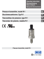
Pressure transmitter, model R-1
Druckmessumformer, Typ R-1
Pressure transmitter, model R-1
Transmetteur de pression, type R-1
Transmisor de presión, modelo R-1

2 WIKA operating instructions pressure transmitter, model R-1
EN
DE
FR
ES
14026284.02 09/2018 EN/DE/FR/ES
Operating instructions model R-1 Page 3 - 24
Betriebsanleitung Typ R-1 Seite 25 - 46
Mode d'emploi type R-1 Page 47 - 68
Manual de instrucciones modelo R-1 Página 69 - 91
© 2012 WIKA Alexander Wiegand SE & Co. KG
All rights reserved. / Alle Rechte vorbehalten.
WIKA
®
is a registered trademark in various countries.
WIKA
®
ist eine geschützte Marke in verschiedenen Ländern.
Prior to starting any work, read the operating instructions!
Keep for later use!
Vor Beginn aller Arbeiten Betriebsanleitung lesen!
Zum späteren Gebrauch aufbewahren!
Lire le mode d'emploi avant de commencer toute opération !
A conserver pour une utilisation ultérieure !
¡Leer el manual de instrucciones antes de comenzar cualquier trabajo!
¡Guardar el manual para una eventual consulta!

3WIKA operating instructions pressure transmitter, model R-1
14026284.02 09/2018 EN/DE/FR/ES
EN
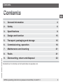
Contents
Contents
Declarations of conformity can be found online at www.wika.com.
1. General information 4
2. Safety 6
3. Specications 9
4. Design and function 15
5. Transport, packaging and storage 15
6. Commissioning, operation 16
7. Maintenance and cleaning 21
8. Faults 21
9. Dismounting, return and disposal 23

4 WIKA operating instructions pressure transmitter, model R-1
14026284.02 09/2018 EN/DE/FR/ES
EN
1. General information
1. General information
■
The pressure transmitter described in the operating instructions has been designed and
manufactured using state-of-the-art technology. All components are subject to stringent quality and
environmental criteria during production. Our management systems are certied to ISO 9001 and
ISO 14001.
■
These operating instructions contain important information on handling the instrument. Working
safely requires that all safety instructions and work instructions are observed.
■
Observe the relevant local accident prevention regulations and general safety regulations for the
instrument's range of use.
■
The operating instructions are part of the product and must be kept in the immediate vicinity of the
instrument and readily accessible to skilled personnel at any time.
■
Skilled personnel must have carefully read and understood the operating instructions prior to
beginning any work.
■
The manufacturer's liability is void in the case of any damage caused by using the product contrary
to its intended use, non-compliance with these operating instructions, assignment of insuciently
qualied skilled personnel or unauthorised modications to the instrument.
■
The general terms and conditions contained in the sales documentation shall apply.
■
Subject to technical modications.
■
Further information:
- Internet address: www.wika.de / www.wika.com
- Relevant data sheet: PE 81.45
- Application consultant:
Tel.: +49 9372/132-0
Fax: +49 9372/132-406
E-mail: info@wika.de

5WIKA operating instructions pressure transmitter, model R-1
14026284.02 09/2018 EN/DE/FR/ES
EN
1. General information
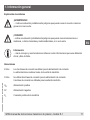
Explanation of symbols
WARNING!
... indicates a potentially dangerous situation that can result in serious injury or death, if not
avoided.
CAUTION!
... indicates a potentially dangerous situation that can result in light injuries or damage to the
equipment or the environment, if not avoided.
Information
... points out useful tips, recommendations and information for ecient and trouble-free
operation.
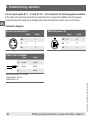
Abbreviations
2-wire The two connection lines are used for the voltage supply.
The measurement signal also provides the supply current.
3-wire Two connection lines are used for the power supply.
One connection line is used for the measurement signal.
U
B
Positive power supply terminal
0V Negative power supply terminal
S
+
Positive output terminal

6 WIKA operating instructions pressure transmitter, model R-1
14026284.02 09/2018 EN/DE/FR/ES
EN
2. Safety
2. Safety
WARNING!
Before installation, commissioning and operation, ensure that the appropriate pressure
transmitter has been selected in terms of measuring range, design and specic measuring
conditions.
Non-observance can result in serious injury and/or damage to the equipment.
WARNING!
■
Open the connections only after the system has been depressurised.
■
Observe the working conditions in accordance with chapter 3 "Specications".
■
Always operate the pressure transmitter within the overpressure limit.
Further important safety instructions can be found in the individual chapters of these
operating instructions.
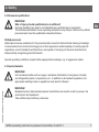
2.1 Intended use
The pressure transmitter is used to convert pressure into an electrical signal.
The instrument has been designed and built solely for the intended use described here, and may only
be used accordingly.
The technical specications contained in these operating instructions must be observed.
Improper handling or operation of the pressure transmitter outside of its technical specications requires
the instrument to be taken out of service immediately and inspected by an authorised WIKA service
engineer.
The manufacturer shall not be liable for claims of any type based on operation contrary to the intended use.

7WIKA operating instructions pressure transmitter, model R-1
14026284.02 09/2018 EN/DE/FR/ES
EN
2. Safety
2.2 Personnel qualication
WARNING!
Risk of injury should qualication be insucient!
Improper handling can result in considerable injury and damage to equipment.
The activities described in these operating instructions may only be carried out by skilled
personnel who have the qualications described below.
Skilled personnel
Skilled personnel are understood to be personnel who, based on their technical training, knowledge
of measurement and control technology and on their experience and knowledge of country-specic
regulations, current standards and directives, are capable of carrying out the work described and
independently recognising potential hazards.
Special operating conditions require further appropriate knowledge, e.g. of aggressive media.
2.3 Special hazards
WARNING!
For hazardous media such as oxygen, acetylene, ammable or toxic gases or liquids,
and refrigeration plants, compressors, etc., in addition to all standard regulations, the
appropriate existing codes or regulations must also be followed.
WARNING!
Residual media in dismounted pressure transmitters can result in a risk to persons, the
environment and equipment.
Take sucient precautionary measures.

8 WIKA operating instructions pressure transmitter, model R-1
14026284.02 09/2018 EN/DE/FR/ES
EN
2. Safety
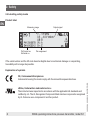
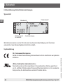
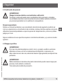
2.4 Labelling, safety marks
Product label
If the serial number and the 2D code become illegible due to mechanical damage or overpainting,
traceability will no longer be possible.
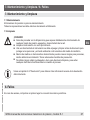
Explanation of symbols
CE, Communauté Européenne
Instruments bearing this mark comply with the relevant European directives.
cRUus, Underwriters Laboratories Inc.
®
The instrument was inspected in accordance with the applicable US standards and
certied by UL. The UL Recognized Component Mark denotes components recognised
by UL that serve as a component of another product.
Output signal
Pin assignment
P# Product no.
S# Serial no.
Measuring range

9WIKA operating instructions pressure transmitter, model R-1
14026284.02 09/2018 EN/DE/FR/ES
EN
3. Specications
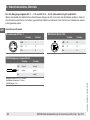
3. Specications
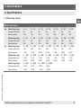
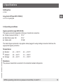
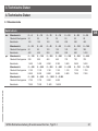
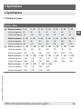
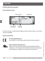
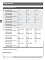
3.1 Measuring ranges
Relative pressure
bar Measuring range 0 ... 6 0 ... 10 0 ... 15 0 ... 16 0 ... 20 0 ... 25 0 ... 30
Overpressure limit 20 20 32 32 50 50 80
Burst pressure 100 100 160 160 250 250 400
Measuring range 0 ... 35 0 ... 40 0 ... 45 0 ... 50 0 ... 60 0 ... 100 0 ... 160
Overpressure limit 80 80 120 120 120 200 320
Burst pressure 400 400 550 550 550 800 1,000
psi Measuring range 0 ... 100 0 ... 150 0 ... 200 0 ... 250 0 ... 300 0 ... 350 0 ... 400
Overpressure limit 290 290 460 460 720 720 720
Burst pressure 1,450 1,450 2,300 2,300 3,600 3,600 3,600
Measuring range 0 ... 450 0 ... 500 0 ... 550 0 ... 600 0 ... 650 0 ... 700 0 ... 750
Overpressure limit 1,100 1,100 1,100 1,100 1,100 1,700 1,700
Burst pressure 5,800 5,800 5,800 5,800 5,800 7,900 7,900
Measuring range 0 ... 800 0 ... 850 0 ... 1,500 0 ... 2,400
Overpressure limit 1,700 1,700 2,900 4,600
Burst pressure 7,900 7,900 11,600 14,500

10 WIKA operating instructions pressure transmitter, model R-1
14026284.02 09/2018 EN/DE/FR/ES
EN
3. Specications
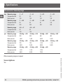
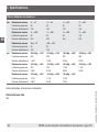
Vacuum and +/- measuring range
bar Measuring range -1 ... +7 -1 ... +9 -1 ... +10 -1 ... +15
Overpressure limit 20 20 20 32
Burst pressure 100 100 100 160
Measuring range -1 ... +20 -1 ... +25 -1 ... +29 -1 ... +45
Overpressure limit 50 50 80 120
Burst pressure 250 250 400 550
Measuring range -0.5 ... +7 -0.5 ... +10
Overpressure limit 20 20
Burst pressure 100 100
psi Measuring range -30 inHg ... +100
-30
inHg
... +145 -30
inHg
... +200 -30
inHg
... +250
Overpressure limit 290 290 460 460
Burst pressure 1,450 1,450 2,300 2,300
Measuring range
-30
inHg
... +300 -30
inHg
... +350 -30
inHg
... +400 -30
inHg
... +450
Overpressure limit 720 720 1,100 1,100
Burst pressure 3,600 3,600 5,800 5,800
Measuring range
-30
inHg
... +500 -30
inHg
... +550 -30
inHg
... +600
Overpressure limit 1,100 1,100 1,700
Burst pressure 5,800 5,800 7,900
Other measuring ranges on request
Vacuum tightness
Yes

11WIKA operating instructions pressure transmitter, model R-1
14026284.02 09/2018 EN/DE/FR/ES
EN
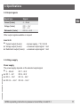
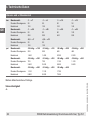
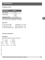
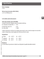
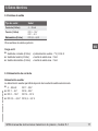
3.2 Output signals
Signal type Signal
Current (2-wire) 4 ... 20 mA
Voltage (3-wire) DC 0 ... 10 V
DC 1 ... 5 V
Ratiometric (3-wire) DC 0.5 ... 4.5 V
Other output signals available on request
Load in Ω
■
Current output (2-wire): ≤ (power supply - 7 V) / 0.02 A
■
Voltage output (3-wire): > maximum output signal / 1 mA
■
Ratiometric output (3-wire): > maximum output signal / 1 mA
3.3 Voltage supply
Power supply
The power supply depends on the selected output signal
■
4 ... 20 mA: DC 7 ...30 V
■
DC 1 ... 5 V: DC 8 ...30 V
■
DC 0 ... 10 V: DC 14 ... 30 V
■
DC 0.5 ... 4.5 V: DC 4.5 ... 5.5 V
3. Specications

12 WIKA operating instructions pressure transmitter, model R-1
14026284.02 09/2018 EN/DE/FR/ES
EN
3. Specications
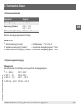
3.4 Reference conditions (per IEC 61298-1)
Temperature
15 ... 25 °C
Atmospheric pressure
860 ... 1,060 mbar
Humidity
45 ... 75 % relative
Power supply
DC 24 V
Nominal position
Calibrated in vertical mounting position with pressure connection facing downwards.
3.5 Accuracy data
Accuracy at reference conditions
≤ 2 % of span
Including non-linearity, hysteresis, zero oset and end value deviation (corresponds to measured error
per IEC 61298-2).
Temperature error at -25 ... +85 °C
Mean temperature coecient of zero point: typical ≤ 0.5% of span/10 K
Mean temperature coecient of span: ≤ 0.3 % of span/10 K

13WIKA operating instructions pressure transmitter, model R-1
14026284.02 09/2018 EN/DE/FR/ES
EN
3. Specications
Settling time
≤ 5 ms
Long-term drift (per IEC 61298-2)
≤ 0.3 % of span/year
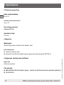
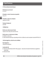
3.6 Operating conditions
Ingress protection (per IEC 60529)
The ingress protection depends on the type of electrical connection.
■
Circular connector M12 x 1: IP 67
■
Metri-Pack series 150: IP 67
■
Cable outlet: IP 69K
The stated ingress protection only applies when plugged in using mating connectors that have the
appropriate ingress protection.
Temperatures
■
Medium: -40 ... +100 °C -40 ... +212 °F
■
Ambient: -25 ... +85 °C -13 ... +185 °F
■
Storage: -25 ... +85 °C -13 ... +185 °F
Resistance
The pressure transmitter is resistant to the industrial standard refrigerants

14 WIKA operating instructions pressure transmitter, model R-1
14026284.02 09/2018 EN/DE/FR/ES
EN
3. Specications
3.7 Electrical connections
Short-circuit resistance
S
+
vs. 0V
Reverse polarity protection
U
B
vs. 0V
Overvoltage protection
maximum DC 36 V
Insulation voltage
DC 500 V
3.8 Materials
Wetted parts
Sensor and process connection from stainless steel
Non-wetted parts
■
Case from stainless steel
■
Electrical connection from highly resistant, glass-bre reinforced plastic PBT GF 30
3.9 Approvals, directives and certicates
Approvals
cRUus (recognition)
CE conformity
■
EMC directive, EN 61326 emission (group 1, class B) and interference immunity (industrial application)
■
RoHS direcitve

15WIKA operating instructions pressure transmitter, model R-1
14026284.02 09/2018 EN/DE/FR/ES
EN
3. Specications / 4. Design and function / 5. Transport ...
For special model numbers, e.g. R-10000, please note the specications stated on the delivery note.
For further specications see WIKA data sheet PE 81.45 and the order documentation.
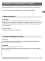
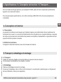
4. Design and function
4.1 Description
The prevailing pressure is measured at the sensor element through the deformation of a diaphragm.
By supplying power, this deformation of the diaphragm is converted into an electrical signal. The output
signal from the pressure transmitter is amplied and standardised. The output signal is proportional to
the measured pressure.
4.2 Scope of delivery
Cross-check scope of delivery with delivery note.
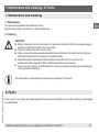
5. Transport, packaging and storage
5.1 Transport
Check the pressure transmitter for any damage that may have been caused during transportation.
Obvious damage must be reported immediately.
5.2 Packaging
Do not remove packaging until just before mounting.
Keep the packaging as it will provide optimum protection during transport (e.g. change in installation
site, sending for repair).

16 WIKA operating instructions pressure transmitter, model R-1
14026284.02 09/2018 EN/DE/FR/ES
EN
5. Transport, packaging and storage / 6. Commissioning, operation
5.3 Storage
Permissible conditions at the place of storage:
Storage temperature: -25 ... +85 °C [-13 ... +185 °F]
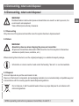
WARNING!
Before storing the pressure transmitter (following operation), remove any residual media.
This is of particular importance if the medium is hazardous to health, e.g. caustic, toxic,
carcinogenic, radioactive, etc.
6. Commissioning, operation
CAUTION!
Prior to commissioning, the pressure transmitter must be subjected to a visual inspection.
Only use the pressure transmitter if it is in perfect condition with respect to safety.
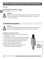
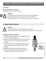
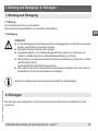
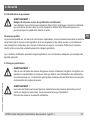
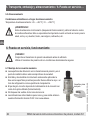
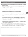
6.1 Making the mechanical connection
■
The sealing faces at the pressure transmitter and the measuring
point always have to be clean.
■
Only ever screw in, or unscrew, the instrument via the spanner ats.
Never use the case or the cooling element as a working surface.
■
The correct torque depends on the dimensions of the process
connection and the gasket used (form/material).
■
When screwing in, do not cross the threads.
■
For information on tapped holes and welding sockets, see
Technical Information IN 00.14 at www.wika.com.
Spanner ats

17WIKA operating instructions pressure transmitter, model R-1
14026284.02 09/2018 EN/DE/FR/ES
EN
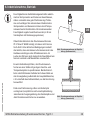
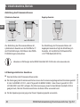
6. Commissioning, operation
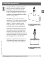
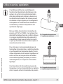
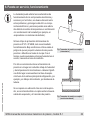
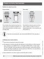
Humidity can aect the operating characteristics of
electronic components and sensors, thus a good
positioning prevents problems and extends the
service life. Electronic components and sensors can
be adversely aected due to temperature changes in
combination with condensing humidity (e.g. in evapo-
rators with de-icing systems).
Although the ingress protection of the pressure
transmitter is IP 67 or IP 6K9K, this is not hermetically
sealed. Under critical conditions, there is the danger
that small air volumes can penetrate or diuse
through the case. Thus, over time, humidity can
collect in the sensor and cause measuring errors.
It is therefore recommended that the pressure trans-
mitter is placed in a location with low humidity and
temperature uctuations. For chill cabinets or cold
rooms, this place is on the inlet pipe on the outside of
the main cooling chamber, e.g. below the chill cabinet
where the piping comes out of the chill cabinet.
If positioning is required closer to the evaporator, it is
recommended that a capillary is used between the
evaporator outlet line and the pressure transmitter.
Fig.: Pressure transmitter with capillary
(exterior view)
Fig.: Pressure transmitter with capillary
(cross-section)

18 WIKA operating instructions pressure transmitter, model R-1
14026284.02 09/2018 EN/DE/FR/ES
EN
6. Commissioning, operation
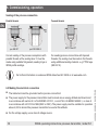
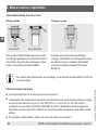
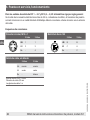
Sealing of the process connection
Parallel threads
Tapered threads
Correct sealing of the process connections with
parallel threads at the sealing face must be
made using suitable at gaskets, sealing rings or
WIKA prole sealings.
For sealing process connections with tapered
threads, the sealing must be made in the threads
using additional sealing material - e.g. PTFE tape
(EN 837-2).
For further information on seals see WIKA data sheet AC 09.08 or at www.wika.com.
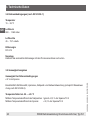
6.2 Making the electrical connection
■
The instrument must be grounded via the process connection!
■
The power supply for the pressure transmitter must be made via an energy-limited electrical circuit
in accordance with section 9.3 of UL/EN/IEC 61010-1, or an LPS to UL/EN/IEC 60950-1, or class 2
in accordance with UL1310/UL1585 (NEC or CEC). The power supply must be suitable for operation
above 2,000 m should the pressure transmitter be used at this altitude.
■
For the voltage supply, use a class 2 voltage source.
per EN 837 per DIN 3852-E
NPT, R and PT

19WIKA operating instructions pressure transmitter, model R-1
14026284.02 09/2018 EN/DE/FR/ES
EN
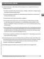
6. Commissioning, operation
■
Conditions of acceptability - When installed in the nal use equipment, etc., the following are among
the considerations to be made:
1. The instrument must be installed in accordance with the enclosure, mounting, spacing, and segre-
gation requirements of the nal application.
2. The clearances given here (air and leakage paths), nominal values, etc. must be permissible
within the nal application.
3. This component is intended to be factory installed only.
4. The connectors of these instruments have not been tested for their suitability for eld wiring
connectors ("eld wiring"). The acceptability of the terminals, and connections to these terminals,
including temperature and safety, must be evaluated in the end-product application.
5. On the instrument, there is no isolated equipotential bonding terminal or connection line available
(that would maintain the equipotential bonding during dismantling in the live state by a service
technician for testing or setting purposes). This requirement depends on the application and the
standards applicable to the end product.
6. The mould stress test was conducted at 110 °C and the suitability will be dened with the
end-product application.
■
Select a cable diameter that matches the cable gland of the plug. Make sure that the cable gland of
the mounted plug has a tight t and that the seals are present and undamaged. Tighten the threaded
connection and check that the seal is correctly seated, in order to ensure the ingress protection.
■
For cable outlets, make sure that no moisture enters at the cable end.

20 WIKA operating instructions pressure transmitter, model R-1
14026284.02 09/2018 EN/DE/FR/ES
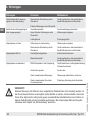
EN
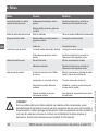
6. Commissioning, operation
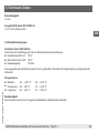
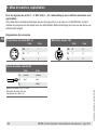
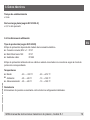
For the output signals DC 1 ... 5 V and DC 0.5 ... 4.5 V ratiometric, the following applies in addition:
If the cable of the electrical connection is longer than 30 m or leaves the building, then the pressure
transmitter should be used with a shielded cable. Earth the shield on at least one end of the lead.
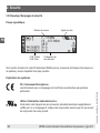
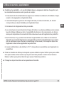
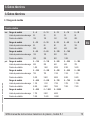
Connection diagrams
Circular connector M12 x 1
2-wire 3-wire
U
B
1 1
0V 3 3
S+ - 4
Metri-Pack series 150
2-wire 3-wire
U
B
B B
0V C A
S+ - C
Cable outlet, unshielded
2-wire 3-wire
U
+
brown brown
U
-
green green
S
+
- white
Wire cross-section 3 x 0.14 mm
2
Cable diameter 3.2 mm
Cable lengths 1 m
Seite wird geladen ...
Seite wird geladen ...
Seite wird geladen ...
Seite wird geladen ...
Seite wird geladen ...
Seite wird geladen ...
Seite wird geladen ...
Seite wird geladen ...
Seite wird geladen ...
Seite wird geladen ...
Seite wird geladen ...
Seite wird geladen ...
Seite wird geladen ...
Seite wird geladen ...
Seite wird geladen ...
Seite wird geladen ...
Seite wird geladen ...
Seite wird geladen ...
Seite wird geladen ...
Seite wird geladen ...
Seite wird geladen ...
Seite wird geladen ...
Seite wird geladen ...
Seite wird geladen ...
Seite wird geladen ...
Seite wird geladen ...
Seite wird geladen ...
Seite wird geladen ...
Seite wird geladen ...
Seite wird geladen ...
Seite wird geladen ...
Seite wird geladen ...
Seite wird geladen ...
Seite wird geladen ...
Seite wird geladen ...
Seite wird geladen ...
Seite wird geladen ...
Seite wird geladen ...
Seite wird geladen ...
Seite wird geladen ...
Seite wird geladen ...
Seite wird geladen ...
Seite wird geladen ...
Seite wird geladen ...
Seite wird geladen ...
Seite wird geladen ...
Seite wird geladen ...
Seite wird geladen ...
Seite wird geladen ...
Seite wird geladen ...
Seite wird geladen ...
Seite wird geladen ...
Seite wird geladen ...
Seite wird geladen ...
Seite wird geladen ...
Seite wird geladen ...
Seite wird geladen ...
Seite wird geladen ...
Seite wird geladen ...
Seite wird geladen ...
Seite wird geladen ...
Seite wird geladen ...
Seite wird geladen ...
Seite wird geladen ...
Seite wird geladen ...
Seite wird geladen ...
Seite wird geladen ...
Seite wird geladen ...
Seite wird geladen ...
Seite wird geladen ...
Seite wird geladen ...
Seite wird geladen ...
-
 1
1
-
 2
2
-
 3
3
-
 4
4
-
 5
5
-
 6
6
-
 7
7
-
 8
8
-
 9
9
-
 10
10
-
 11
11
-
 12
12
-
 13
13
-
 14
14
-
 15
15
-
 16
16
-
 17
17
-
 18
18
-
 19
19
-
 20
20
-
 21
21
-
 22
22
-
 23
23
-
 24
24
-
 25
25
-
 26
26
-
 27
27
-
 28
28
-
 29
29
-
 30
30
-
 31
31
-
 32
32
-
 33
33
-
 34
34
-
 35
35
-
 36
36
-
 37
37
-
 38
38
-
 39
39
-
 40
40
-
 41
41
-
 42
42
-
 43
43
-
 44
44
-
 45
45
-
 46
46
-
 47
47
-
 48
48
-
 49
49
-
 50
50
-
 51
51
-
 52
52
-
 53
53
-
 54
54
-
 55
55
-
 56
56
-
 57
57
-
 58
58
-
 59
59
-
 60
60
-
 61
61
-
 62
62
-
 63
63
-
 64
64
-
 65
65
-
 66
66
-
 67
67
-
 68
68
-
 69
69
-
 70
70
-
 71
71
-
 72
72
-
 73
73
-
 74
74
-
 75
75
-
 76
76
-
 77
77
-
 78
78
-
 79
79
-
 80
80
-
 81
81
-
 82
82
-
 83
83
-
 84
84
-
 85
85
-
 86
86
-
 87
87
-
 88
88
-
 89
89
-
 90
90
-
 91
91
-
 92
92


in anderen Sprachen
- français: WIKA R-1 Mode d'emploi
- español: WIKA R-1 Instrucciones de operación
Verwandte Artikel
-
WIKA MH-1 Bedienungsanleitung
-
-
-
-
WIKA S-11 Bedienungsanleitung
-
-
-
-
-