
DE
EN
© 2021 BD|SENSORS GmbH -
Alle Rechte vorbehalten / All rights reserved
BD-Sensors-Str.1; 95199 Thierstein
Telefon: +49 (0) 92 35 / 98 11 0 | www.bdsensors.de
ID: MA_TS_D-E | Version: 03.2021.0
Montageanleitung /
Mounting instructions
Tauchsonden DCL mit Modbus RTU Schnittstelle RS485
Tauchsonde LMK / LMP
Probe DCL with Modbus RTU interface RS485
Probe LMK / LMP
DCL 531, DCL 551, DCL 571, LMK 306, LMK 307,
LMK 307T, LMK 309, LMK 358, LMK 358H, LMK 382,
LMK 382H, LMK 387, LMK 387H, LMK 806, LMK 807,
LMK 808, LMK 809, LMK 858, LMP 305, LMP 307,
LMP 307i, LMP 307T, LMP 308, LMP 308i, LMP 808
VOR GEBRAUCH SORGFÄLTIG LESEN
AUFBEWAHREN FÜR SPÄTERES NACHSCHLAGEN
Diese Montageanleitung stellt einen Auszug
aus der ausführlichen Betriebsanleitung dar.
Bitte laden Sie sich diese auf unserer Home-
page herunter, falls Sie nicht mit dem Produkt
vertraut sind.
These mounting instructions are an excerpt from the complete
operating manual. It may be downloaded from our homepage, if
you are not familiar with the device.
http://www.bdsensors.de
– Technische Änderungen vorbehalten –
– Technical modifications reserved –
WARNUNG - Um Gefährdungen des Bedienpersonals und
Schäden am Gerät auszuschließen, müssen die beschriebenen
Arbeiten von qualifiziertem Fachpersonal durchgeführt werden.
WARNUNG - Halten Sie sich an Sicherheitshinweise und
Handlungsanweisungen, die in der Betriebsanleitung aufgeführt
werden. Zusätzlich sind die geltenden Unfallverhütungsvor-
schriften, Sicherheitsbestimmungen sowie landesspezifische In-
stallationsstandards und die anerkannten Regeln der Technik
einzuhalten.
Haftungsbeschränkung
Bei Nichtbeachtung der Montage- / Betriebsanleitung, unsach-
gemäßer Verwendung, Veränderung oder Beschädigung des
Gerätes übernimmt der Hersteller keine Haftung.
Bestimmungsgemäße Verwendung
Stellen Sie sicher, dass das Messmedium mit den medienbe-
rührten Teilen verträglich und das Gerät uneingeschränkt für die
Anwendung geeignet ist. Die im aktuellen Datenblatt aufgeführ-
ten technischen Daten sind verbindlich.
Produktidentifikation
Montage
Befestigen Sie die Tauchsonde sachgemäß entsprechend Ihren
Anforderungen. Das Gerät ist grundsätzlich langsam in das zu
messende Medium eintauchen! Ein Aufschlagen der Sonde auf
der Flüssigkeitsoberfläche kann die Membrane beschädigen
oder zerstören.
Bei LMK 382 / LMK 382H in Flanschausführung ist sicher-zu-
stellen, dass das Montagegewinde sauber und unbeschadet ist
und der O-Ring unbeschadet in der vorgesehenen Nut am Son-
denende sitzt. Nach Einschrauben der Sonde von Hand, ist
diese mit dem Maulschlüssel (ca. 25 Nm) festzuziehen.
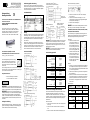
Anschlussschaltbilder
2-Leiter-System (Strom)
2-Leiter System (Strom) HART
2x2-Leiter-System (Strom) bei LMK 307T / LMP 307T
3-Leiter-System (Strom/Spannung)
2-Leiter-System HART® (Druck) /
3-Leiter-Anschluss (Temperatur Pt 100)
RS 485 / Modbus RTU
RS 485 / Modbus RTU mit Reset-Funktion
HINWEIS - Bei Relativgeräten enthält das Kabel einen Belüf-
tungsschlauch für den Druckausgleich. Führen Sie das Kabel-
ende in einen Bereich oder geeigneten Anschlusskasten, der
möglichst trocken und frei von aggressiven Gasen ist, um eine
Beschädigung zu vermeiden.
HINWEIS - Verwenden Sie für den elektrischen Anschluss
eine geschirmte und verdrillte Mehraderleitung.
Anschlussbelegungstabelle
Elektrische Anschlüsse
Kabelfarben (IEC 60757)
Versorgung +
Versorgung −
Signal + (bei 3-Leiter)
bei Option Pt 100:
Versorgung T+
Versorgung T–
Versorgung T–
wh (weiß)
bn (braun)
gn (grün)
ye (gelb)
gy (grau)
pk (rosa)
Schirm
gnye (grün / gelb)
LMK 307T und LMP 307T
Kabelfarben (IEC 60757)
Versorgung P+
Versorgung P–
Versorgung T+
Versorgung T–
wh (weiß)
bn (braun)
gy (grau)
pk (rosa)
Schirm
gnye (gelb / grün)
DCL 531, DCL 551, DCL 571
Kabelfarben (IEC 60757)
Versorgung +
Versorgung −
A +
B -
DCL 531: Reset
wh (weiß)
bn (braun)
gn (grün)
ye (gelb)
pk (rosa)
Schirm
gnye (gelb / grün)
Abziehen der Schutzkappe (falls erforderlich)
Zum Schutz der Membrane sind einige Tauchsonden mit einer
Kunststoff-Schutzkappe ausgestattet. Ist ein Einsatz der
Tauchsonde in höher viskosen Medien wie z. B. Schlämmen
vorgesehen, ist diese vor Inbetriebnahme abzuziehen. Dadurch
wird die Tauchsonde frontbündig und das Medium gelangt an
die Membrane.
Abziehen von Hand
1. Halten Sie die Tauchsonde so, dass die Schutzkappe nach
oben zeigt.
2. Halten Sie mit einer Hand die Sonde am Sondenteil (1)
fest.
3. Ziehen Sie mit der anderen Hand die Schutzkappe (2) ab.
Abziehen mit Werkzeug (empfohlen)
1. Halten Sie die Tauchsonde so, dass die Schutzkappe
nach oben zeigt.
2. Schieben Sie ein dünnes Werkzeug (8), z. B. einen
Schraubendreher, gerade durch zwei gegenüberliegende
Bohrungen der Schutzkappe (2).
3. Hebeln Sie die Schutzkappe ab.
HINWEIS - Achten Sie dabei unbedingt darauf, dass Sie die
Messzelle (7) unter der Schutzkappe nicht beschädigen!
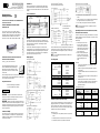
Trennbarkeit (bei LMK 358, LMK 358H, LMK 808, LMK 858,
LMP 308, LMP 308i und LMP 808)
Zur Vereinfachung von Lagerhaltung und Wartung ist der Son-
denkopf von dem Kabelteil trennbar und kann bei Bedarf ohne
aufwendige Montagearbeiten ausgetauscht werden.
Demontage
1. Halten Sie die Tauchsonde mit
einer Hand am Sondenteil (2)
fest und drehen Sie mit der an-
deren Hand die Überwurf-mut-
ter (4) vorsichtig nach links. Be-
achten Sie dabei, dass das Ka-
belteil (3) nicht gegenüber dem
Gehäuse verdreht werden darf!
2. Halten Sie den Sondenteil (2)
beim Abschrauben vom Kabel-
teil (3) gerade und ziehen Sie
ihn nach dem Lösen gerade ab,
damit die Stecker-Verbindung
nicht beschädigt wird.
Montage
✓ O-Ringe (5, 6) sind nicht beschädigt bzw. Beschädigte wur-
den ausgetauscht; Radial-O-Ringe (5) sind mit Vaseline o-
der O-Ring-Fett eingefettet; etwaige Fettrückstände wurden
vom Axial-O-Ring (6) entfernt.
1. Stecken Sie das Kabelteil (3) gerade in den Gegenstecker
des Sondenteils (2).
2. Halten Sie die Tauchsonde mit einer Hand am Sondenteil
(2) fest und schrauben Sie mit der anderen Hand die Über-
wurfmutter (4) wieder fest auf. Beachten Sie dabei, dass
das Kabelteil (3) nicht gegenüber dem Gehäuse verdreht
werden darf!
Steckerbelegung
Elektrische
Anschlüsse
Binder Serie 723
(5-polig)
Binder Serie 723
(7-polig)
2-Leiter-System
Versorgung +
Versorgung −
3
1
3
1
Schirm
5
2
3-Leiter-System
Versorgung +
Versorgung −
Signal +
3
4
1
3
1
6
Schirm
5
2
Kommunikationsschnittstelle
RxD
TxD
GND
-
-
-
4
5
7
Versorgung +
Versorgung –
UB
A
p
I
Versorgung +
Signal +
UB
A/V
p
I/U
Versorgung –
UB
Versorgung +
Versorgung -
A (+)
B (-)
p
RS485
p
Versorgung +
Versorgung –
UB
I
I
I
+
Versorgung P+
Versorgung P-
Versorgung T+
Versorgung T-
UB
A
p
T
UB
A
–
+
–
Bestellcode
Typenbezeichnung
Seriennummer
LMP 308
Deutsch
Versorgung UB+
Versorgung UB−
Versorgung T+
Versorgung T−
Versorgung T−
UB
P
I
Option Pt 100-
Temperaturfühler
Reset
Versorgung -
UB
A (+)
B (-)
p
RS485
Versorgung +

DE
EN
© 2021 BD|SENSORS GmbH -
Alle Rechte vorbehalten / All rights reserved
BD-Sensors-Str.1; 95199 Thierstein
Telefon: +49 (0) 92 35 / 98 11 0 | www.bdsensors.de
ID: MA_TS_D-E | Version: 03.2021.0
Montageanleitung /
Mounting instructions
Tauchsonden DCL mit Modbus RTU Schnittstelle RS485
Tauchsonde LMK / LMP
Probe DCL with Modbus RTU interface RS485
Probe LMK / LMP
DCL 531, DCL 551, DCL 571, LMK 306, LMK 307,
LMK 307T, LMK 309, LMK 358, LMK 358H, LMK 382,
LMK 382H, LMK 387, LMK 387H, LMK 806, LMK 807,
LMK 808, LMK 809, LMK 858, LMP 305, LMP 307,
LMP 307i, LMP 307T, LMP 308, LMP 308i, LMP 808
READ THOROUGHLY BEFORE USING THE DEVICE
KEEP FOR FUTURE REFERENCE
Diese Montageanleitung stellt einen Auszug
aus der ausführlichen Betriebsanleitung dar.
Bitte laden Sie sich diese auf unserer Home-
page herunter, falls Sie nicht mit dem Produkt
vertraut sind.
These mounting instructions are an excerpt from the complete
operating manual. It may be downloaded from our homepage, if
you are not familiar with the device.
http://www.bdsensors.de
– Technische Änderungen vorbehalten –
– Technical modifications reserved –
WARNING - In order to avoid hazards to operators and
damages to the device, the following instructions have to be
performed by qualified technical personnel.
WARNING - Adhere to the safety and operating instructions
stated in the operation manual. Effective regulations on occupa-
tional safety, accident prevention as well as national installation
standards and approved engineering techniques must in addi-
tion be complied with.
Limitation of liability
If the instructions in the mounting instructions / operating man-
ual are not adhered to or if the device is inappropriately used,
modified or damaged, liability is not assumed and warranty
claims will be excluded.
Intended use
Ensure that the medium is compatible with the media-wetted
parts and that the device is suitable for the application without
restrictions. The technical data listed in the current data sheet is
binding.
Product identification
Mounting
Fasten the probe properly according to your requirements. Al-
ways immerse the device slowly into the fluid to be measured! If
the probe strikes the liquid surface, the diaphragm could be
damaged or destroyed.
For LMK 382 / LMK 382H in flange version ensure that the
mounting thread is clean and undamaged and that the O-ring is
undamaged and seated in the designated groove at the probe
end. After screwing in by hand, the probe has to be tighten us-
ing an open-end wrench (approx. 25 Nm).
Wiring diagrams
2-wire-system (current)
2-wire-system (current) HART
2x2-wire-system (current) for LMK 307T / LMP 307T
3-wire-system (current/supply)
2-wire-system HART
(pressure) /
3-wire-system (temperature Pt 100)
RS 485 / Modbus RTU
RS 485 / Modbus RTU with reset function
NOTE - In the case of relative pressure gauges, the cable con-
tains a ventilation hose for pressure equalization. Route the end
of the cable into an area or suitable connection box which is as
dry as possible and free from aggressive gases, in order to pre-
vent any damage.
NOTE - Use a shielded and twisted multicore cable for the
electrical connection.
Pin configuration
Electrical connections
cable colours (IEC 60757)
Supply +
Supply −
Signal + (with 3-wire)
with option Pt 100: Supply T+
Supply T–
Supply T–
wh (white)
bn (brown)
gn (green)
ye (yellow)
gy (grey)
pk (pink)
Shield
gnye (yellow/green)
LMK 307T and LMP 307T
cable colours (IEC 60757)
Supply P+
Supply P–
Supply T+
Supply T–
wh (white)
bn (brown)
gy (grey)
pk (pink)
Shield
gnye (yellow/green)
DCL 531, DCL 551, DCL 571
cable colours (IEC 60757)
Supply +
Supply –
A +
B -
DCL 531: Reset
wh (white)
bn (brown)
gn (green)
ye (yellow)
pk (pink)
Shield
gnye (yellow/green)
Removal of protective cap (if necessary)
For the protection of the diaphragm, some of the probes have a
plugged-on protection cap. If the device shall be used in high-
viscosity media such as sludge, a removal of the cap before
start-up is necessary. Thus, the sensor becomes flush and the
medium will attain quickly to the diaphragm.
Removal by hand
1. Hold the probe in a way that the protection cap points up-
wards.
2. Hold the probe with one hand on the sensor section (1).
3. Remove the protection cap (2) with the other hand.
Removal with a tool (recommended)
1. Hold the probe in a way that the protection cap points up-
wards.
2. Slide a small tool such as a screwdriver (8) straight through
two opposite drill holes in the protective cap (2).
3. Lever it off by moving up the handle of the screwdriver.
NOTE - Make sure that the sensor (7) under the protection
cap will not be damaged!
Separability (with LMK 358, LMK 358H, LMK 808, LMK 858,
LMP 308, LMP 308i and LMP 808)
In order to facilitate stock keeping and maintenance, the probe
head is plugged to the cable assembly with a connector and can
be easily changed.
Disassembly
1. Hold the probe on the sensor
section (2) with one hand and
turn the nut (4) carefully to the
left with the other hand. Prevent
torsion of the cable section (3)
against the housing!
2. While screwing and pulling off
the sensor section (2) from the
cable section (3), hold it straight
to prevent damages on the
plugs.
Assembly
✓ O-rings are not damaged (5, 6) or damaged O-rings
have been replaced.
✓ Radial O-rings (5) have been greased with Vaseline or
O-ring grease.
✓ Any grease residues have been removed from the axial
O-ring (6).
1. Plug the cable section (3) straight into the plug of the sen-
sor section (2).
2. Hold the probe onto the sensor section (2) with one
hand. Screw on and tighten the nut (4) carefully with the
other hand. Prevent torsion of the cable section (3)
against the housing!
Pin configuration of plug
Electrical
connections
Binder series 723
(5-pin)
Binder series 723
(7-pin)
2-wire system
Supply +
Supply −
3
1
3
1
Shield
5
2
3-wire system
Supply +
Supply −
Signal +
3
4
1
3
1
6
Shield
5
2
Communication interface
RxD
TxD
GND
-
-
-
4
5
7
English
Type Ordering code Serial
designation number
supply +
supply –
VS
A
p
I
supply +
signal +
VS
A/V
p
I/U
supply –
p
supply +
supply –
VS
I
VS
supply +
supply -
A (+)
B (-)
p
RS485
I
I
+
supply P+
supply P-
supply T+
supply T-
VS
A
p
T
VS
A
–
+
–
supply VS+
supply VS −
supply T+
supply T−
supply T−
VS
P
I
option Pt 100-
temperature
element
LMP 308
Reset
supply -
UB
A (+)
B (-)
p
RS485
supply +
-
 1
1
-
 2
2


