
Warnhinweise
Warnings
Montageanleitung
Mounting Instructions
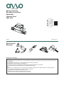
LMK 3010
Abtastkopf
Scanning Head
AMO GmbH
AMO GmbH
A-4963 St. Peter am Hart
Nöng 4
Phone: +43 7722 658 56-0
e-mail: o[email protected]
www.amo-gmbh.com
1230440-01-A-0104/2018
Achtung:
• Die Montage und Inbetriebnahme ist von einer qualizierten Fachkraft unter Beachtung der örtlichen Sicherheitsvorschriften
vorzunehmen.
• Die Steckerverbindung darf nur spannungsfrei verbunden oder gelöst werden.
• Montageächen müssen sauber und gratfrei sein.
• Der direkte Kontakt von Flüssigkeiten mit Messgerät und Steckverbinder ist zu vermeiden.
• Der Antrieb darf während der Montage nicht in Betrieb gesetzt werden.
Note:
• Mounting and commissioning is to be conducted by a qualied specialist under compliance with local safety regulations.
• Do not engage or disengage any connections while under power.
• Mounting surfaces must be clean and free of burrs.
• Avoid direct contact of uids with the encoder and connector.
• The drive must not be put into operation during mounting.
Warnhinweise - Warnings

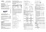
Montage
Assembly
Allgemeine Hinweise
General Informations
Den Messwagen mit der Montagehilfe an der Stirnseite der
Schiene andrücken und vorsichtig aufschieben unter
Berücksichtigung von:
Referenzmarke des Messwagens muss auf der gleichen Seite
sein wie die RI-Markierungsplättchen (siehe Bild bei Abmes-
sungen)
Es gibt 2 mögliche Montagearten:
a) exible Montage über Federelement
b) feste Montage
Engage the measuring slider on the rail from the rail end with
help of the mounting aid, considering:
Reference track mark of the slider must be on the same rail
side as the RI marking label. (see picture in dimensions)
There are 2 possible ways for mounting the reading head:
a) exible mounting with the spring element
b) xed mounting
Mindestabstand von Störquellen
Minumum distance from sources of interference
Elektrischen Widerstand zwischen Steckergehäuse und
Maschine prüfen. Sollwert: 1 Ohm max.
Check the resistance between the connector housing and
machine. Desired value: 1 Ohm max.
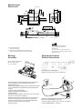
2x
4,5
11 10
M3/5 deep
2
58
52
~9
4,5
23,5
31,5
Mounting spring
34
24
46,5
2x
3,3
H2
RI Marking plate
52x10x0,5
H2
Scale fixing bracket
51
2
19
39
46
H3
H2 = Referenzspur-Markierung
= Reference track marking
H3 = Verfahrrichtung des Abtastkopfes für positive Zählrichtung
= Direction of scanning head movement for positive counting
Abmessungen
Dimensions
Tolerance priciple in accordance with ISO 8015
General tolerances in accordance with ISO 2768-fH
All dimensions in mm
Tolerierungsgrundsatz nach ISO 8015
Allgemeintoleranz nach ISO 2768-fH
Alle Maße in mm
Tolerierungsgrundsatz nach ISO 8015
Allgemeintoleranz nach ISO 2768-fH
Alle Maße in mm
Tolerance principle in accordance with ISO 8015
General tolerances in accordance with ISO 2768-fH
All dimensions in mm
M3 mit 1,00Nm Anzugsmoment
M3 with 1,00Nm Torque
M
d
= 1,00 ± 0,05Nm
-
 1
1
-
 2
2


in anderen Sprachen
- English: AMO LMK 3010
Verwandte Artikel


Andere Dokumente
-
ACU-RITE LMK 3010 Benutzerhandbuch
-
Baumer HMC16 Installation and Operating Instructions
-
HEIDENHAIN LIP 471R Mounting instructions
-
SICK SKS/SKM36S, safety Motor feedback system rotary HIPERFACE® Bedienungsanleitung
-
-
Fagor SV2A Series Bedienungsanleitung
-
-
 Simex LMK 382 Bedienungsanleitung
