
DE
EN
BD-Sensors-Str.1; 95199 Thierstein
Telefon: +49 (0) 92 35 / 98 11 0 | www.bdsensors.de
© 2021 BD|SENSORS GmbH -
Alle Rechte vorbehalten / All rights reserved
ID: MA_DMU-ES-OEM_D-E | Version: 02.2021.0
Montageanleitung /
Mounting instructions
Druckmessumformer / Pressure Transmitter,
Einschraubsonde / Screw-in Transmitter
OEM-Druckmessumformer / OEM Pressure Transmitter
DMK 331, DMK 331P, DMK 351, DMK 351P, DMK 387,
DMP 311, DMP 320, DMP 321, DMP 331, DMP 331i,
DMP 331P, DMP 331Pi, DMP 333, DMP 333i, DMP 334,
DMP 334i, DMP 335, DMP 336, DMP 335P, DMP 339,
DMP 339P, DMP 343, LMK 331, LMK 351, LMP 331,
LMP 331i, 17.6XX, 17.6XX G, 18.6XX, 18.6XX G,
26.6XX, 26.6XX G, 30.6XX, 30.6XX G
VOR GEBRAUCH SORGFÄLTIG LESEN
AUFBEWAHREN FÜR SPÄTERES NACHSCHLAGEN
READ THOROUGHLY BEFORE USING THE DEVICE
KEEP FOR FUTURE REFERENCE
Diese Montageanleitung stellt einen Auszug
aus der ausführlichen Betriebsanleitung dar.
Laden Sie sich diese auf unserer Homepage
herunter, falls Sie nicht mit dem Produkt
vertraut sind.
These mounting instructions are an excerpt from the complete
operating manual. It may be downloaded from our homepage,
if you are not familiar with the device.
http://www.bdsensors.de
– Technische Änderungen vorbehalten –
– Technical modifications reserved –
WARNUNG - Um Gefährdungen des Bedienpersonals und
Schäden am Gerät auszuschließen, müssen die beschriebenen
Arbeiten von qualifiziertem Fachpersonal durchgeführt werden.
WARNUNG - Halten Sie sich an Sicherheitshinweise und
Handlungsanweisungen, die in der Betriebsanleitung aufgeführt
werden. Zusätzlich sind die geltenden Unfallverhütungsvor-
schriften, Sicherheitsbestimmungen sowie landesspezifische
Installationsstandards und die anerkannten Regeln der Technik
einzuhalten.
Haftungs- und Gewährleistungsbeschränkung
Nichtbeachtung der Montage- / Betriebsanleitung und techni-
schen Vorschriften, unsachgemäße und nicht bestimmungsge-
mäße Verwendung, Veränderung oder Beschädigung des Gerä-
tes führen zu Verlust der Gewährleistungs- und Haftungsan-
sprüche.
Bestimmungsgemäße Verwendung
Stellen Sie sicher, dass das Messmedium mit den medienbe-
rührten Teilen verträglich und das Gerät uneingeschränkt für die
Anwendung geeignet ist. Die im aktuellen Datenblatt aufgeführ-
ten technischen Daten sind verbindlich.
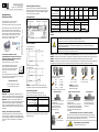
Produktidentifikation
Anschlussschaltbilder
2-Leiter-System (Strom)
3-Leiter-System (Strom / Spannung)
HINWEIS - Verwenden Sie für den elektrischen Anschluss
vorzugsweise eine geschirmte und verdrillte Mehraderleitung.
Anschlussbelegungstabelle
optional mit Kommunikationsschnittstelle RS232 bei
DMP 331i / DMP 331Pi / DMP 333i / DMP 334i / LMP 331i:
Elektrische Anschlüsse
Binder 723 (7-polig)
Versorgung +
Versorgung –
Signal + (nur für 3-Leiter)
3
1
6
Schirm
2
RxD
TxD
GND
4
5
7
HINWEIS - Die Kommunikationsschnittstelle RS232 darf nicht
direkt mit dem PC verbunden werden. Ein passender Adapter ist
als Zubehör erhältlich.
Montage
DMP 331
Typenbezeichnung Bestellcode Seriennummer
Deutsch
Versorgung +
Versorgung –
U
B
A
p
I
Versorgung +
Signal +
U
B
A
/
V
p
I/U
Versorgung –
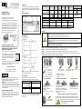
Elektrische Anschlüsse ISO 4400
Binder 723
(5-polig)
Kabelfarben
(IEC 60757)
Feld-
gehäuse
Buccaneer
(4-polig)
TRIM TRIO
(4-polig)
Bajonett MIL-C-26482 (10-6)
2-Leiter
3-Leiter
Versorgung +
Versorgung –
Signal + (nur für 3-Leiter)
1
2
3
3
4
1
WH (weiß)
BN (braun)
GN (grün)
IN +
IN –
OUT +
1
2
3
1
2
3
A
B
-
A
D
B
Schirm Masse-
kontakt
5 GNYE
(grün/gelb)
4 4 Druckanschluss
Elektrische Anschlüsse
M12x1 Metall (4-polig)
Micro
Code
M10 / M20
M13 (17.620G)
C10
CB0 (17.620G)
Versorgung +
Versorgung –
Signal + (nur für 3-Leiter)
1
2
3
1
3
2
1
2
3
1
3
2
Schirm
4
Steckergehäuse
Massekontakt
Massekontakt
HINWEIS -
Die Anschlussbelegung für abweichende elektrische Anschlüsse ist dem Typenschild zu entnehmen.
GEFAHR
Lebensgefahr durch davonfliegende Teile, austretendes Medium, Stromschlag
- Montieren Sie das Gerät immer im druck- und stromlosen Zustand!
- Betreiben Sie das Gerät nur innerhalb der Spezifikation! (gemäß Datenblatt)
Lebensgefahr bei nicht bestimmungsgemäßer Installation
- Durchführung der Installation nur von fachspezifisch qualifiziertem Personal, das die Betriebsanleitung
gelesen und verstanden hat!
Lebensgefahr durch Explosion in Sauerstoff-Anwendungen bei unsachgemäßer Verwendung
- Beachten Sie die Anweisungen in der Betriebsanleitung!
HINWEIS - Beachten Sie für Geräte mit 3-A Symbol oder UL-Kennzeichnung die entsprechenden Vorgaben in der Betriebsanleitung.
HINWEIS - Verwenden Sie, soweit erforderlich, zur Abdichtung eine geeignete Dichtung, entsprechend Messstoff und zu messenden Druck.
HINWEIS - Verwenden Sie für Anschlüsse nach DIN 3852 kein zusätzliches Dichtmaterial wie Werg, Hanf oder Teflonband.
HINWEIS - Der erforderliche Anzugsmoment richtet sich nach den Gegebenheiten vor Ort (Werkstoff und Geometrie der Aufnahmestelle).
Die angegebenen Anzugsmomente gelten für Druckmessumformer/Einschraubsonden und dürfen nicht überschritten werden!
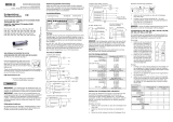
DMP 331P:
74-
Anschluss nach DIN 3852 Anschluss nach EN 837 NPT-Anschluss 1/4" Bördel
Kordelring: nur von Hand festschrauben
Schlüsselweite aus Metall:
G1/4": ca. 5 Nm G1/4": ca. 20 Nm 1/4" NPT: ca. 30 Nm max. 10 Nm
G1/2": ca. 10 Nm G1/2": ca. 50 Nm 1/2" NPT: ca. 70 Nm
G3/4": ca. 15 Nm
G1": ca. 20 Nm
G1 1/2": ca. 25 Nm
Schlüsselweite aus Kunststoff: max. 3 Nm
Milchrohr-Anschluss Clamp- und Varivent-Anschluss Flansch-Anschluss
- Zentrieren Sie den Anschluss in der - Zentrieren Sie den Anschluss in der Befestigen Sie den Flansch
Aufnahmearmatur. Aufnahmearmatur. mit 4 bzw. 8 Schrauben (je
- Schrauben Sie die Überwurfmutter - Befestigen Sie das Gerät anschließend nach Flanschausführung) am
auf die Aufnahmearmatur. durch ein geeignetes Verbindungselement Gegenflansch.
- Ziehen Sie diese mit einem (z. B. Halbring- oder Klappringverbindung) .
Hakenschlüssel fest. gemäß den vom Hersteller angegebenen
Vorschriften.
G1" Konus Innengewinde M20x1,5 und 9/16" UNF (bei DMP 334 / DMP 334i)
Schrauben Sie Ihre Hochdruckverschraubung gemäß der Herstellervorschriften in
das Innengewinde am DMP 334 / DMP 334i und ziehen Sie es ordnungsgemäß fest.
pN < 10 bar: 30 Nm (zul. Anzugsmoment für Druckmessumformer max. 120 Nm)
pN ≥ 10 bar: 60 Nm
HINWEIS - Beachten Sie
die zulässigen Drücke
und
Materialien nach EN 837.
WARNUNG
Verletzungsgefahr durch falsche Montage
-Verwenden Sie keine Dichtung!

DE
EN
BD-Sensors-Str.1; 95199 Thierstein
Telefon: +49 (0) 92 35 / 98 11 0 | www.bdsensors.de
© 2021 BD|SENSORS GmbH -
Alle Rechte vorbehalten / All rights reserved
ID: MA_DMU-ES-OEM_D-E | Version: 02.2021.0
Montageanleitung /
Mounting instructions
Druckmessumformer / Pressure Transmitter,
Einschraubsonde / Screw-in Transmitter
OEM-Druckmessumformer / OEM Pressure Transmitter
DMK 331, DMK 331P, DMK 351, DMK 351P, DMK 387,
DMP 311, DMP 320, DMP 321, DMP 331, DMP 331i,
DMP 331P, DMP 331Pi, DMP 333, DMP 333i, DMP 334,
DMP 334i, DMP 335, DMP 336, DMP 335P, DMP 339,
DMP 339P, DMP 343, LMK 331, LMK 351, LMP 331,
LMP 331i, 17.6XX, 17.6XX G, 18.6XX, 18.6XX G,
26.6XX, 26.6XX G, 30.6XX, 30.6XX G
VOR GEBRAUCH SORGFÄLTIG LESEN
AUFBEWAHREN FÜR SPÄTERES NACHSCHLAGEN
READ THOROUGHLY BEFORE USING THE DEVICE
KEEP FOR FUTURE REFERENCE
Diese Montageanleitung stellt einen Auszug
aus der ausführlichen Betriebsanleitung dar.
Laden Sie sich diese auf unserer Homepage
herunter, falls Sie nicht mit dem Produkt
vertraut sind.
These mounting instructions are an excerpt from the complete
operating manual. It may be downloaded from our homepage,
if you are not familiar with the device.
http://www.bdsensors.de
– Technische Änderungen vorbehalten –
– Technical modifications reserved –
WARNING - In order to avoid hazards to operators and
damages to the device, the following instructions have to be
performed by qualified technical personnel.
WARNING - Adhere to the safety and operating instructions
stated in the operation manual. Effective regulations on occupa-
tional safety, accident prevention as well as national installation
standards and approved engineering techniques must in addi-
tion be complied with.
Limitation of liability and warranty
Failure to observe mounting instructions / operating manual or
technical regulations, improper use and use not as intended,
and alteration of or damage to the device will result in the
forfeiture of warranty and liability claims.
Intended use
Ensure that the medium is compatible with the media-wetted
parts and that the device is suitable for the application without
restrictions. The technical data listed in the current data sheet is
binding.
Product identification
Wiring diagrams
2-wire-system (current)
3-wire-system (current / 7voltage)
NOTE - For the electrical connection a shielded and twisted
multicore cable is recommended.
Pin configuration
optionally with communication interface RS232 for
DMP 331i / DMP 331Pi / DMP 333i / DMP 334i / LMP 331i:
Electrical connection
Binder 723 (7-pin)
Supply +
Supply –
Signal + (for 3-wire)
3
1
6
Shield
2
RxD
TxD
GND
4
5
7
NOTE - The communication interface RS232 may not be
connected directly to the PC. A suitable adapter is available as
an accessory.
Mounting
DMP 331
Type designation Ordering code Serial number
English
Electrical connection ISO 4400 Binder 723
(5-pin)
cable
colours
(IEC 60757)
field
housing Buccaneer
(4-pin) TRIM TRIO
(4-pin)
Bayonet
MIL-C-26482 (10-6)
2-wire
3-wire
Supply +
Supply –
Signal + (for 3-wire)
1
2
3
3
4
1
WH (white)
BN (brown)
GN (green)
IN +
IN –
OUT +
1
2
3
1
2
3
A
B
-
A
D
B
Shield
ground
contact
5 GNYE
(green
-yellow)
4 4 pressure port
Electrical connection
M12x1 metal (4-pin)
Micro
Code
M10 / M20
M13 (17.620G)
C10
CB0 (17.620G)
Supply +
Supply –
Signal + (for 3-wire)
1
2
3
1
3
2
1
2
3
1
3
2
Shield
4
plug housing
ground contact
ground contact
NOTE - The pin configuration for different electrical connections can be found on the manufacturing label.
DANGER
Danger of death from airborne parts, leaking fluid, electric shock
- Always mount the device in a depressurized and de-energized condition!
- Operate the device only within the specification! (according to data sheet)
Danger of death from improper installation
- Installation must be performed only by appropriately qualified persons who have read and understood the
operating manual.
Danger of death from explosion in oxygen applications when used improperly
- Follow the instructions in the operating manual!
NOTE - For devices with 3-A symbol or UL marking the corresponding specifications in the operating manual must be observed.
NOTE - Use a suitable seal for the medium and the pressure to be measured, if necessary.
NOTE - For connections according to DIN 3852 do not use any additional sealing material such as yarn, hemp or Teflon tape.
NOTE - The permissible tightening torque depends on the conditions on site (material and geometry of the mounting point). The specified
tightening torques are valid for the transmitters and must not be exceeded!
Supply +
Supply –
V
S
A
p
I
Supply +
Signal +
V
S
A
/ V
p
I/U
Supply –
DMP 331P:
74-
connection according to DIN 3852 connection according to EN 837 NPT connections 1/4" flare
knurled ring: only tighten by hand
wrench size of metal:
G1/4": approx. 5 Nm G1/4": approx. 20 Nm 1/4" NPT: approx. 30 Nm max. 10 Nm
G1/2": approx. 10 Nm G1/2": approx. 50 Nm 1/2" NPT: approx. 70 Nm
G3/4": approx. 15 Nm
G1": approx. 20 Nm
G1 1/2": approx. 25 Nm
wrench size of plastic: max. 3 Nm
dairy pipe connection Clamp- und Varivent connections flange connections
- Centre the dairy pipe connection - Centre the connection above the Install the flange with 4 resp. 8
in the counterpart. counterpart with seal. screws (depending on flange
- Screw the cup nut onto the - Fit the device with a suitable fastening version) on the counter flange.
mounting part. element (e. g. semi-ring or retractable ring
- Then tighten it using a hook wrench. clamp) according to the supplier’s
instructions.
G1" cone internal threads M20x1.5 and 9/16" UNF (for DMP 334 / DMP 334i)
Screw the high-pressure fitting into the internal thread of the pressure transmitter
and tighten it properly. (permissible tightening torque for transmitter: max 120 Nm)
pN < 10 bar: 30 Nm
pN ≥ 10 bar: 60 Nm
WARNUNG
Danger of injury due to wrong installation
-Do not use any seal!
NOTE - note the permitted
pressure
and material acc.
to EN 837.
-
 1
1
-
 2
2


in anderen Sprachen
- English: Simex DMK 331 Owner's manual
Verwandte Artikel


Andere Dokumente
-
Lifetime 80279 Bedienungsanleitung
-
ABB DMP Series Operating And Maintenance Instructions Manual
-
Panasonic DMPBDT171EG Bedienungsanleitung
-
Panasonic DMPBDT100EG Bedienungsanleitung
-
Panasonic DMP-BDT384EG Bedienungsanleitung
-
-
Panasonic DMP-BDT185EG Bedienungsanleitung