
BA-120/240/480 CP

BA-120/240/480 CP
2
Read all safety instruction before operating.
1. Install equipment as follow condition:
- Install at flat place, not bending curved.
- Do not install near the water and moisture.
- Locate power amplifier away from heat source
- Do not drop objects or spill liquids into the inside of amplifier.
2. Keep in mind the following when connecting amplifier.
- Connect the amplifier after reading of O/P manuals.
- Connect each connection of amplifier perfectly,if not, it
maybe caused hum, damage, electric shock in case of
misconnecting.
- To prevent electric shock, do not open top cover.
- Connect the power cord with safety after check of AC
power.
Vor Inbetriebnahme des Verstärkers bitten wir sie, die Sicher-
heitshinweise aufmerksam zu lesen.
1. Installation nach folgenden Richtlinien:
- Stellen sie den Verstärker immer auf eine ebene und stabile
Unterfläche.
- Wählen sie eine trockene Umgebung und stellen sie keine
Flüssigkeiten auf den Gerät.
- Vermeiden sie die Nähe von Heizungen und anderen Hitze-
quellen.
2. Beachten sie folgendes, wenn sie den Verstärker an-
schließen.
- Lesen sie zuerst die Betriebsanleitung
- Öffnen sie niemals das Gehäuse des Verstärkers ohne den
Netzstecker zu ziehen.
- Schließen sie das Gerät nur an 230 V Netzspannung oder
24 V/DC Notstromversorgung.
SICHERHEITSHINWEISE
FEATURES
1 Automatic speed variable fan with ball bearing.
2. Over current protection.
3. Full protection.
4. Multiple load impedance.
5. Noise reduction circuitry when Power-On.
6. Soft start of AC Power-On.
7. Program and Priority Audio Input.
8. Priority control signal input terminal is adopted.
MERKMALE
1. Kugelgelagerte Lüfter mit automatischer Geschwindigkeits-
regelung.
2. Für den Dauereinsatz ausgelegt, absolut kurzschluss- und
leerlaufsicher.
3. 100 V bzw. 70 V und 8 Ohm Ausgänge.
4. "SOFT START" und spezieller Schaltkreis zur Unterdrü-
ckung von Einschaltgeräuschen.
5. Elektronisch symmetrierte Eingänge für Programm und
Priorität .
6. Phönix-Stecker verringern den Verdrahtungsaufwand we-
sentlich.
7. Monitorausgang zur Kontrolle des Programms.
SAFETY INSTRUCTIONS

BA-120/240/480 CP
3
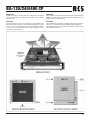
MOUNTING
Amplifier racking size BA series are designed for standard
19" rack mounting. Please pay close attention to the cooling
requirements.
COOLING
Never block the air vents rear and front of the amplifier. The
following is figure of airflow. Check inside temperature of rack
system so as not to be more than 40°C for the stable operating
in any case, we recommend you to install cooling fan on the
rear panel of rack cabinet.
MONTAGE
Die Verstärker sind mit seitlichen Befestigungswinkeln für den
Einbau in 19" Gestelle versehen. Zusätzlich empfiehlt sich die
Verwendung von Gleitschienen.
KÜHLUNG
Die Luftöffnungen an Vorder- und Rückseite dürfen nicht blo-
ckiert sein, so wird ein optimaler Kühlluftfluß gewährleistet.
Die Verwendung eines zusätzlichen Rack-Lüfters kann unter
Umständen sinnvoll sein.

BA-120/240/480 CP
4
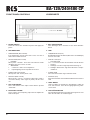
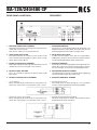
FRONT PANEL CONTROLS VORDERSEITE
1. POWER SWITCH
Power this switch "ON" will make the power and supply the
power.
2. LED INDICATORS
• TEMPERATURE (RED COLOR).
If the temperature of heat-sink is 100°C more, red color of
LED indicator will be flashed.
• PROTECTION (RED COLOR)
- NORMAL:
When power "ON/OFF". Red color LED indicator will be
disappear after two or three seconds.
- ABNORMAL:
1. Continuous- Under over temperature
2. Repeat ligthing On/Off- Speaker line shorten
• POWER (YELLOW COLOR)
When power "ON" makes yellow color.
• PRIORITY (RED COLOR)
When priority control is activated, PGM audio signal is
closed and Priority audio signal of priority will be come
out.
3. OUT LEVEL METER
This is LED LEVEL meter. Adjust volume before clip LED
"TURN ON".
4. PGM LEVEL VOLUME
This is volume control adjusting output level of amplifier for
PGM audio input.
1. EIN- /AUSSCHALTER
Nach Betätigen dieses Schalters ist das Gerät betriebs-
bereit.
2. LED`s
• TEMPERATUR LED (Rot).
Bei Überhitzung des Verstärkers (über 100°C am Kühlkörper)
leuchtet diese LED.
• PROTECT LED (Rot)
- Normal Betrieb:
Ca. 2 - 3 s nach Einschalten des Verstärkers erlischt die LED.
- Störung:
1. Ständiges Leuchten zeigt Temperatur Warnung an.
2. Ständiges Aufleuchten zeigt Kurzschluß der Lautspre-
cherlinie an.
• POWER (Gelb)
Diese LED leuchtet bei eingeschaltetem Gerät.
• PRIORITY (Rot)
Wenn der Verstärker im Prioritätsbetrieb läuft leuchtet diese
LED.
3. LEVEL METER
LED Level Meter als Anzeige des Signalpegels, wobei die
CLIP LED leuchtet, wenn die Ausgangsspannung über-
steuert wird.
4. LAUTSTÄRKEREGLER
Dieser Regler bestimmt die Lautstärke des Programms nicht
aber die Lautstärke des Prioritätsignals.

BA-120/240/480 CP
5
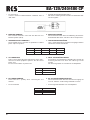
REAR PANEL CONTROLS RÜCKSEITE
1. PROGRAM AUDIO INPUT TERMINAL
Audio input terminal of Program signal (for normal announ-
cment) with screw terminal.
Input level is +4dBu (1,23 V) 30 kΩ balanced.
2. 400 Hz (HIGH PASS FILTER)
This makes reduction of resonance sound inside to make
clear sound when pushing high pass filter, frequency range
will be deducted at 6 dB/oct.
3. PRIORITY AUDIO INPUT TERMINAL
Audio input terminal of Priority signal (for E/M announcement
and Remote announcement) with screw terminal.
4. PRIORITY LEVEL VOLUME
This is for controller of output level against Priority audio
input signal.
5. PRIORITY CONTROL INPUT TERMINAL
• +24 V Terminal
When control priority by external switch contact point or ex-
ternal relay contact point, use terminal of switch contact.
1. PROGRAMM EINGANG
Symmetrischer Audio Eingang (INPUT) für Programm- und
Signaleinspeisung, wobei durch die Phönix-Stecker der
Verdrahtungsaufwand wesentlich verringert wird.
2. 400 Hz HIGH PASS FILTER
Schalter zum Zuschalten eines 400 Hz Hochpassfilters
(6dB/Oktave), wodurch Innenresonanzen reduziert werden
und die Wiedergabequalität erhöht werden kann.
3. PRIORITÄT EINGANG
Symmetrischer Audio Eingang (INPUT) für Signale die Pri-
orität haben sollen (z.B. Notruf und Durchsagen). Phönix-
Stecker verringern auch hier den Verdrahtungsaufwand.
4. REGLER FÜR PRIORITÄTSSIGNAL
Lautstärkeregler mit dem das Prioritätssignal unabhängig
vom Masterregler eingestellt werden kann.
5. PRIORITÄT KONTROLL KLEMME
• Priorität durch 24 V DC
Die Priorität kann wie unten gezeigt mit +24 V geschaltet
werden, die Hintergrundmusik wird stark gedämpft.
• Terminal for switch contact point
When control priority by external switch contact point or ex-
ternal relay contact point, use terminal of switch contact.
• Priorität durch potentialfreien Kontakt
Mit dieser Schaltung ist es möglich, die Priorität mit einem
potentialfreien Kontakt auszulösen.

BA-120/240/480 CP
6
• For JRG-220 A
Connect terminal of AMP PRIORITY CONTROL OUT of
JRG-220 A.
• Priorität durch Relaisfeld JRG-220 A
Mit dieser Schaltung wird die Priorität vom Relaisfeld JRG-
220 A ausgelöst.
6. MONITOR TERMINAL
This terminal should be connected with MU-307 A or
Monitor Speaker (100 V).
7. SPEAKER OUTPUT TERMINALS
These terminals are for connection of speaker lines to deliver
power output to speakers.
6. MONITOR AUSGANG
Dieser Klemmanschluß dient zur Anbindung des Monitor-
Kontrollfeldes MU-307 A oder eines 100 V Lautsprechers.
7. LAUTSPRECHERAUSGÄNGE
Hoch- und niederohmige Lautsprecherausgänge; Näheres
entnehmen Sie bitte der Tabelle.
BA-120 CP
BA-240 CP
BA-480 CP
5,2 Ω / 25 V
2,6 Ω / 25 V
8 Ω / 31 V
8 Ω / 44 V
8 Ω / 62 V
41 Ω / 70 V
20 Ω / 70 V
10 Ω / 70 V
42 Ω / 100 V
83 Ω / 100 V
21 Ω / 100 V
8. AC POWER INLET
Please connect power plug after main power switch "OFF",
when fuse is blown-up please replace it after disconnect
power cord.
Fuse located in FU201 on power PCB.
8. NETZ - KALTGERÄTESTECKER
Anschluß für das mitgelieferte Netzkabel. Bei Ausfall der
Sicherung darf diese nur durch den selben Typ ersetzt
werden.
Die Sicherung FU201 ist zu finden auf der Netzplatine.
BA-480 CP
BA-240 CP
BA-120 CP
T2AH 250 V (55T)
T3,15AH 250 V (55T)
T6,3AH 250 V (55T)
9. DC POWER TERMINAL
Please note the +,- polarity, when connecting DC 24 V
terminal.
• Fuse PCB FU202
9. DC 24 V NOTSTROMVERSORGUNG
Dieser Klemmanschluß dient der Notstromversorgung mit
24 V DC, dabei ist auf die richtige Polarität zu achten.
• Sicherung FU202 befindet sich auf Netzplatine.
BA-480 CP
BA-240 CP
BA-120 CP
T10AL 250 V (65TL)
T20AL 32 V (AFE)
T40AL 32 V (ULATC)

BA-120/240/480 CP
7

BA-120/240/480 CP
8
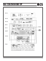
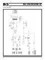
BLOCK DIAGRAM

BA-120/240/480 CP
9
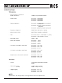
TECHNICAL
- Input sensitivity / impedance
(PGM, PRIORITY) +4dBu(1.23V)/30KΩ BALANCED
- Rated Output BA-120CP : 120W(RMS)
BA-240CP : 240W(RMS)
BA-480CP : 480W(RMS)
- Output Impedance BA-120CP : (5.2Ω)25V, (8Ω)31V, (41Ω)70V,
(83Ω)100V
BA-240CP : (2.6Ω)25V, (8Ω)44V, (20Ω)70V,
(42Ω)100V
BA-480CP : (8Ω)62V, (10Ω)70V, (21Ω)100V
- Frequency Response LESS THAN -3dB (35Hz ~ 20kHz)
- Signal to Noise Ratio MORE THAN 100dB („A“ WEIGHT)
- THD BA-120CP, 240CP : LESS THAN 1% (1kHz)
BA-480CP : LESS THAN 2% (1kHz)
- Input Filter (H.P.F) 400Hz / -3dB
- Power Consumption BA-120CP : 335W
BA-240CP : 650W
BA-480CP : 1380W
- 1/8 Power Current draw 120V/230V BA-120CP : 1.4A / 0.7A
BA-240CP : 2.8A / 1.4A
BA-480CP : 6A / 3A
- 1/3 Power Current draw 120V/230V BA-120CP : 2.2A / 1.1A
BA-240CP : 4A / 2A
BA-480CP : 8A / 4A
- Rated Power Current draw 120V/230V BA-120CP : 3.4A / 1.7A
BA-240CP : 6.6A / 3.3A
BA-480CP : 13A / 6.7A
SPECIFICATIONS
GENERAL
- Power 120V/220V/230V/240VAC 50-60Hz
24VDC
- Dimensions (mm) 483(W) x 88(H) x 374(D)
(inches) 19(W) x 3.5(H) x 14.7(D)
- Weight (kg/lbs) BA-120CP : 10.5 / 23
BA-240CP : 12.5 / 27.6
BA-480CP : 15.5 / 34.2
NOTE
Specifications and design subject to change without notice for improvements.

BA-120/240/480 CP
10
NOTE :

BA-120/240/480 CP
11
NOTE:

BA-120/240/480 CP
Lieferung durch:
Electromagnetic compatibility and low-voltage guidelines: RCS leaves all devices and products, which are subject to the CE guidelines by certified test laboratories test.
By the fact it is guaranteed that you may sell our devices in Germany and in the European Union domestic market without additional checks.
Elektromagnetische Verträglichkeit und Niederspannungsrichtlinien: RCS läßt alle Geräte und Produkte, die den CE-Richtlinien unterliegen durch zertifizierte Prüflabors
testen. Dadurch ist sichergestellt, dass Sie unsere Geräte in Deutschland und im EU-Binnenmarkt ohne zusätzliche Prüfungen verkaufen dürfen.
RCS31.10.2006
-
 1
1
-
 2
2
-
 3
3
-
 4
4
-
 5
5
-
 6
6
-
 7
7
-
 8
8
-
 9
9
-
 10
10
-
 11
11
-
 12
12


RCS BA-120CP Bedienungsanleitung
- Typ
- Bedienungsanleitung
in anderen Sprachen
- English: RCS BA-120CP Owner's manual
Verwandte Artikel
-
RCS BA-2120, 2240CP Bedienungsanleitung
-
-
-
-
-
-
-
-
-