
www.tillig.com
www.facebook.com/tilligbahn
368301 / 22.08.2019
– 1 –
Güterwagen
Bausatz EW 1 • Kit EW 1
Stavebnice EW 1 • Zestaw EW 1
Art.-Nr. / Item no. / Réf. / Art.-č. / Nr art.: 83432
(DE) EW 15° links, Bausatz • (GB) left points kit 15
(FR) EW 15° gauche, Kit • (CZ) EW 15° levá, stavebnice
(PL) Rozjazd EW 15° lewy, Zestaw
Art.-Nr. / Item no. / Réf. / Art.-č. / Nr art.: 83433
(DE) EW 15° rechts, Bausatz • (GB) right points kit 15°
(FR) EW 15° droite, Kit • (CZ) EW 15° pravá, stavebnice
(PL) Rozjazd EW 15° prawy, Zestaw
2.
D i e k u r z e n S t r o m b r ü c k e n 3 a n S c h w e l l e
Nr. 16 jeweils zwischen Mittelschiene und Außenschiene, d. h.
zwischen 5 und 11 bzw. zwischen 4 und 10 einbauen. Dazu
werden die kurzen Strombrücken 3 nach Abstand der
Kernlöcher vorgebogen, von der Rückseite des Schwellenbandes
1 durch die entsprechenden Kernlöcher eingeschoben und die
nach oben aus den Kleineisen ragenden Enden in
Einschieberichtung der jeweiligen Schienen umgelegt.
Die Kontaktblättchen 6 so in die Kleineisen der Mittelschienen ab
Schwelle Nr. 12 einschieben, dass sie mit der Bohrung über den
Drehzapfenlöchern in Schwelle Nr. 11 zu liegen kommen.
D i e M i t t e l s c h i e n e S t a m m g l e i s 4 ( 2 8 , 6 m m )
ab Schwelle Nr. 12 in die Kleineisen bis zur Flügelschiene des
Herzstückes einschieben.
D i e M i t t e l s c h i e n e Z w e i g g l e i s 5 ( 2 9 , 1 m m )
an den Radius anpassen und ab Schwelle Nr. 12 in die Kleineisen
bis an die Flügelschiene des Herzstückes einschieben.
Die langen Strombrücken 2 an der Schwelle Nr. 22 zwischen
Endschiene Stammgleis 15 und Außenschiene Zweiggleis 10
sowie an Schwelle Nr. 23 zwischen Endschiene Zweiggleis 14
und Außenschiene Stammgleis 11 einbauen. Dazu ist
sinngemäß wie unter Punkt 1 zu verfahren.
Die Endschienen Zweiggleis 14 (31,1 mm) sowie Stammgleis 15
(31,8 mm) mit der gefrästen Schräge bis an das Herzstück
einschieben.
Bei Verwendung des TILLIG-Weichenantriebes den kleineren
Adapter 12 an Schwelle Nr. 3 und den größeren Adapter 13 an
Schwelle Nr. 18 einhängen. Der TILLIG-Weichenantrieb kann
mittels Adapter nur an der Stammgleisseite angebaut werden.
Die Stellschwelle 9 mit den Stellkerben nach oben in das
Stellfach zwischen Schwelle Nr. 4 und 5 einlegen.
Die Außenschiene Zweiggleis 10 gemäß dem Radius vorbiegen
und in die entsprechende Kleineisenreihe einschieben. Die
Ausklinkung des Schienenfußes muss auf der Zungenseite über
dem Stellfach zwischen Schwelle Nr. 4 und 5 zu liegen kommen.
Die Außenseite Stammgleis 11 in die entsprechende
Kleineisenreihe einschieben. Die Ausklinkung des Schienenfußes
muss auf der Zungenseite über dem Stellfach zwischen Schwelle
Nr. 4 und 5 zu liegen kommen.
Die Zunge Stammgleis 7 sowie die Zunge Zweiggleis 8 jeweils
mit den Drehzapfen durch das Kontaktblättchen 6 im
Drehzapfenloch in Schwelle Nr. 11 einhängen und mit dem
Stellzapfen im jeweiligen Langloch der Stellschwelle 9
einhängen. Danach die Weiche mit der Oberseite auf eine harte
und glatte Unterlage (Stahlplatte) legen und mittels Hammer
und Körner die Drehzapfen und Stellzapfen leicht vernieten.
Ausrichten der Außenschienen 10 bzw. 11 am Weichenende
rechtwinklig zu den entsprechenden Endschienen 14 bzw. 15.
Aufstecken der Schienenverbinder 16 jeweils in Fahrtrichtung
linke Schiene.
Fixierung der Außen- und Endschienen durch Eindrücken von
Plast- und Sekundenkleber in einige Kernlöcher auf der Rückseite
der Weiche.
M O N T A G E A N L E I T U N G A S S E M B L Y I N S T R U C T I O N S
368300-S.2
09.10.2012
TILLIG Modellbahnen GmbH
Promenade 1, 01855 Sebnitz
Tel. +49 (0)35971 903-0, www.tillig.com
Nicht geeignet für Kinder unter 3 Jahren wegen abnehmbarer
und verschluckbarer Kleinteile und Verletzungsgefahr durch
funktionsbedingte scharfe Ecken und Kanten.
Not suitable for children under 3 years due to danger of
swallowing removable small parts and risk of injury on
account of unavoidable sharp corners and edges.
0-3
Dieses Produkt darf am Ende seiner Nutzungsdauer
nicht über den normalen Hausmüll entsorgt werden, sondern
muss an einem Sammelpunkt für das Recycling von elektrischen
und elektronischen Geräten abgegeben werden.iiiiiiiiiiiiiiiiiiiiiiiiiii
Bitte fragen Sie bei Ihrem Händler oder der Gemeindeverwaltung
nach der zuständigen Entsorgungsstelle.
1.
3.
4.
5.
6.
7.
8.
9.
10.
11.
12.
13.
14.
2.
Insert the short current bridges 3 at sleeper number 16
between the centre and end rails, i.e. between 5 and 11, a n d
between 4 and 10. The current bridges 3 must be pre-bend in
accordance with the hole spacing and pushed through the
corresponding core holes from the underside of the sleeper strip
1. The ends protruding up from the fittings are then bent over in
the direction in which the individual rails are inserted.
Match both contact plates 6 into the corresponding row of
fittings from sleeper number 12. The drilling of the contact
plates 6 have to be at the drilling of the sleepe strip 1 at sleeper
number 11.
Insert the centre rail of the main line 4 (28,6 mm) into the
corresponding row of fittings from sleeper number 12 up to the
wing rails of the frog.
Match the pre-bend centre rail of the branch line 5 (29,1 mm) to
the length and radius and insert it into the corresponding row of
fittings from sleeper number 12 up to the wing rails of the frog.
Insert the long current bridges 2 at sleeper number 22 between
the main-line end rail 15 and the branch-line outer rail 10 and at
sleeper number 23 between the branch-line end rail 14 and the
main-line outer rail 11. Proceed in the same way as described for
step 1.
Slide the end rails of the branch line 14 (31,1 mm) and main line
15 (31,8 mm) (with the milled-off end first) into the
corresponding rows of fittings up to the frog tip.
If the TILLIG points operating gear is used, the little adapter 12 is
hooked at sleeper 3 and the large adapter 13 is hooked at sleeper
18. It is only possible to mount the TILLIG points operating gear
at the side of the main-line.
Insert the switching sleeper 9 (switching notch upwards)
between sleeper number 4 and sleeper number 5.
Match the pre-bend branch-line outer rail 10 to the radius and
slide into the corresponding row of fittings. The notch of the rail
should be at the inner side at the position of the switching
sleeper ( between sleeper number 4 and sleeper number 5).
Match the pre-bent main-line outer rail 11 to the radius a n d
slide into the corresponding row of fittings. The notch of the rail
should be at the inner side at the position of the switching
sleeper ( between sleeper number 4 and sleeper number 5).
Mount the blade rail of main line 7 and the blade rail of branch
line 8. Press the pivot of the blades 7 and 8 in the drilling of the
contact plates 6 and the drilling of the sleepe strip 1 at sleeper
number 11. Insert the switching pin of the blades 7 and 8 into
the long hole of the switching sleeper 9. Further lay the point
(upside down) onto a hard and plain plate (e.g. steel-plate) and
rivet slightly the pivots and the switching pins of the blades by
use of a hammer and a peening tool.
Align the outer rails 10 and 11 at right angles to the
corresponding end rails 14 and 15 at the end of the points.
Fit the track connectors 16 to each left-hand rail (viewed in
running direction).
Fix the outer and end rails by filling a plastic or contact adhesive
into some of the core holes on the underside of the points.
1.
3.
4.
5.
6.
7.
8.
9.
10.
11.
12.
13.
14.
121
13
1
5
10
152025
E W 1 5 ° R E C H T S - B A U S A T Z
16
23
23
11
10 6 9
7
8
4
515
14
16
E W 1 5 ° R I G H T B R A N C H - K I T
Achtung! Weichenbausätze sind mechanische Spielwaren. Ihr Gebrauch birgt
Verletzungsgefahren an scharfkantigen Teilen. Für ihre Montage sind spezielle
Fertigkeiten notwendig.
2.
D i e k u r z e n S t r o m b r ü c k e n 3 a n S c h w e l l e
Nr. 16 jeweils zwischen Mittelschiene und Außenschiene, d. h.
zwischen 5 und 11 bzw. zwischen 4 und 10 einbauen. Dazu
werden die kurzen Strombrücken 3 nach Abstand der
Kernlöcher vorgebogen, von der Rückseite des Schwellenbandes
1 durch die entsprechenden Kernlöcher eingeschoben und die
nach oben aus den Kleineisen ragenden Enden in
Einschieberichtung der jeweiligen Schienen umgelegt.
Die Kontaktblättchen 6 so in die Kleineisen der Mittelschienen ab
Schwelle Nr. 12 einschieben, dass sie mit der Bohrung über den
Drehzapfenlöchern in Schwelle Nr. 11 zu liegen kommen.
D i e M i t t e l s c h i e n e S t a m m g l e i s 4 ( 2 8 , 6 m m )
ab Schwelle Nr. 12 in die Kleineisen bis zur Flügelschiene des
Herzstückes einschieben.
D i e M i t t e l s c h i e n e Z w e i g g l e i s 5 ( 2 9 , 1 m m )
an den Radius anpassen und ab Schwelle Nr. 12 in die Kleineisen
bis an die Flügelschiene des Herzstückes einschieben.
Die langen Strombrücken 2 an der Schwelle Nr. 22 zwischen
Endschiene Stammgleis 15 und Außenschiene Zweiggleis 10
sowie an Schwelle Nr. 23 zwischen Endschiene Zweiggleis 14
und Außenschiene Stammgleis 11 einbauen. Dazu ist
sinngemäß wie unter Punkt 1 zu verfahren.
Die Endschienen Zweiggleis 14 (31,1 mm) sowie Stammgleis 15
(31,8 mm) mit der gefrästen Schräge bis an das Herzstück
einschieben.
Bei Verwendung des TILLIG-Weichenantriebes den kleineren
Adapter 12 an Schwelle Nr. 3 und den größeren Adapter 13 an
Schwelle Nr. 18 einhängen. Der TILLIG-Weichenantrieb kann
mittels Adapter nur an der Stammgleisseite angebaut werden.
Die Stellschwelle 9 mit den Stellkerben nach oben in das
Stellfach zwischen Schwelle Nr. 4 und 5 einlegen.
Die Außenschiene Zweiggleis 10 gemäß dem Radius vorbiegen
und in die entsprechende Kleineisenreihe einschieben. Die
Ausklinkung des Schienenfußes muss auf der Zungenseite über
dem Stellfach zwischen Schwelle Nr. 4 und 5 zu liegen kommen.
Die Außenseite Stammgleis 11 in die entsprechende
Kleineisenreihe einschieben. Die Ausklinkung des Schienenfußes
muss auf der Zungenseite über dem Stellfach zwischen Schwelle
Nr. 4 und 5 zu liegen kommen.
Die Zunge Stammgleis 7 sowie die Zunge Zweiggleis 8 jeweils
mit den Drehzapfen durch das Kontaktblättchen 6 im
Drehzapfenloch in Schwelle Nr. 11 einhängen und mit dem
Stellzapfen im jeweiligen Langloch der Stellschwelle 9
einhängen. Danach die Weiche mit der Oberseite auf eine harte
und glatte Unterlage (Stahlplatte) legen und mittels Hammer
und Körner die Drehzapfen und Stellzapfen leicht vernieten.
Ausrichten der Außenschienen 10 bzw. 11 am Weichenende
rechtwinklig zu den entsprechenden Endschienen 14 bzw. 15.
Aufstecken der Schienenverbinder 16 jeweils in Fahrtrichtung
linke Schiene.
Fixierung der Außen- und Endschienen durch Eindrücken von
Plast- und Sekundenkleber in einige Kernlöcher auf der Rückseite
der Weiche.
M O N T A G E A N L E I T U N G A S S E M B L Y I N S T R U C T I O N S
368300-S.2
09.10.2012
TILLIG Modellbahnen GmbH
Promenade 1, 01855 Sebnitz
Tel. +49 (0)35971 903-0, www.tillig.com
Nicht geeignet für Kinder unter 3 Jahren wegen abnehmbarer
und verschluckbarer Kleinteile und Verletzungsgefahr durch
funktionsbedingte scharfe Ecken und Kanten.
Not suitable for children under 3 years due to danger of
swallowing removable small parts and risk of injury on
account of unavoidable sharp corners and edges.
0-3
Dieses Produkt darf am Ende seiner Nutzungsdauer
nicht über den normalen Hausmüll entsorgt werden, sondern
muss an einem Sammelpunkt für das Recycling von elektrischen
und elektronischen Geräten abgegeben werden.iiiiiiiiiiiiiiiiiiiiiiiiiii
Bitte fragen Sie bei Ihrem Händler oder der Gemeindeverwaltung
nach der zuständigen Entsorgungsstelle.
1.
3.
4.
5.
6.
7.
8.
9.
10.
11.
12.
13.
14.
2.
Insert the short current bridges 3 at sleeper number 16
between the centre and end rails, i.e. between 5 and 11, a n d
between 4 and 10. The current bridges 3 must be pre-bend in
accordance with the hole spacing and pushed through the
corresponding core holes from the underside of the sleeper strip
1. The ends protruding up from the fittings are then bent over in
the direction in which the individual rails are inserted.
Match both contact plates 6 into the corresponding row of
fittings from sleeper number 12. The drilling of the contact
plates 6 have to be at the drilling of the sleepe strip 1 at sleeper
number 11.
Insert the centre rail of the main line 4 (28,6 mm) into the
corresponding row of fittings from sleeper number 12 up to the
wing rails of the frog.
Match the pre-bend centre rail of the branch line 5 (29,1 mm) to
the length and radius and insert it into the corresponding row of
fittings from sleeper number 12 up to the wing rails of the frog.
Insert the long current bridges 2 at sleeper number 22 between
the main-line end rail 15 and the branch-line outer rail 10 and at
sleeper number 23 between the branch-line end rail 14 and the
main-line outer rail 11. Proceed in the same way as described for
step 1.
Slide the end rails of the branch line 14 (31,1 mm) and main line
15 (31,8 mm) (with the milled-off end first) into the
corresponding rows of fittings up to the frog tip.
If the TILLIG points operating gear is used, the little adapter 12 is
hooked at sleeper 3 and the large adapter 13 is hooked at sleeper
18. It is only possible to mount the TILLIG points operating gear
at the side of the main-line.
Insert the switching sleeper 9 (switching notch upwards)
between sleeper number 4 and sleeper number 5.
Match the pre-bend branch-line outer rail 10 to the radius and
slide into the corresponding row of fittings. The notch of the rail
should be at the inner side at the position of the switching
sleeper ( between sleeper number 4 and sleeper number 5).
Match the pre-bent main-line outer rail 11 to the radius a n d
slide into the corresponding row of fittings. The notch of the rail
should be at the inner side at the position of the switching
sleeper ( between sleeper number 4 and sleeper number 5).
Mount the blade rail of main line 7 and the blade rail of branch
line 8. Press the pivot of the blades 7 and 8 in the drilling of the
contact plates 6 and the drilling of the sleepe strip 1 at sleeper
number 11. Insert the switching pin of the blades 7 and 8 into
the long hole of the switching sleeper 9. Further lay the point
(upside down) onto a hard and plain plate (e.g. steel-plate) and
rivet slightly the pivots and the switching pins of the blades by
use of a hammer and a peening tool.
Align the outer rails 10 and 11 at right angles to the
corresponding end rails 14 and 15 at the end of the points.
Fit the track connectors 16 to each left-hand rail (viewed in
running direction).
Fix the outer and end rails by filling a plastic or contact adhesive
into some of the core holes on the underside of the points.
1.
3.
4.
5.
6.
7.
8.
9.
10.
11.
12.
13.
14.
121
13
1
5
10
152025
E W 1 5 ° R E C H T S - B A U S A T Z
16
23
23
11
10 6 9
7
8
4
515
14
16
E W 1 5 ° R I G H T B R A N C H - K I T
Achtung! Weichenbausätze sind mechanische Spielwaren. Ihr Gebrauch birgt
Verletzungsgefahren an scharfkantigen Teilen. Für ihre Montage sind spezielle
Fertigkeiten notwendig.
Zweiggleis
Branch line
Pos.-Nr.
1
2
3
4
5
6
7
8
9
10
11
12
13
14
15
16
No.
1
2
3
4
5
6
7
8
9
10
11
12
13
14
15
16
Bezeichnung
Schwellenband
Strombrücke, lang
Strombrücke, kurz
Mittelschiene Stammgleis
Mittelschiene Zweiggleis
Kontaktblättchen
Zunge Stammmgleis
Zunge Zweiggleis
Stellschwelle
Außenschiene Zweiggleis
Außenschiene Stammgleis
Adapter für Weichenantrieb
Adapter für Weichenantrieb
Endschiene Zweiggleis
Endschiene Stammgleis
Schienenverbinder
Description
Sleepe strip
Current bridge, long
Current bridge, short
Centre rail, main line
Centre rail, branch line
Contact plates
Blade rail, main line
Blade rail, branch line
Switching sleeper
Outer rail, main line
Outer rail, branch line
Adapter for operating gear
Adapter for operating gear
End rail, main line
End rail, branch line
Track connector
The following points operating gear is available:
Electric operating gear for points
item no. 83531 for right points 15° item no. 83431/37
item no. 83532 for left points 15° item no. 83430/36 or
undermounted points operating motor item no. 86112
Stück/Bausatz
1
2
2
1
1
2
1
1
1
1
1
1
1
1
1
3
Pcs/kit
1
2
2
1
1
2
1
1
1
1
1
1
1
1
1
3
Radius
Radius
Bogenwinkel
Curve angle
E I N Z E L T E I L - L I S T E P A R T S L I S T
G L E I S G E O M E T R I E
T R A C K G E O M E T R Y
W E I C H E N A N T R I E B E
P O I N T S O P E R A T I N G G E A R
E W 1 5 ° L I N K S - B A U S A T Z E W 1 5 ° L E F T B R A N C H - K I T
Art.-Nr. 83431 Art.-Nr. 83436 Art.-Nr. 83437
EW 15° rechts
BAUSATZ
EW 15° links
BS brüniert
EW 15° rechts
BS brüniert
EW 15° links
BAUSATZ
Art.-Nr. 83430
Bausatz
EW 15°
left points kit
15°
right points kit
15°
left points kit
15° browned
right points kit
15° browned
Länge
Length
entspr. Passmaß
fit size
Stammgleis 129,5 mm 3 x G3
Main line
Weichenradius 353 mm 15° R 22
point radius
gerader Weichenausgang 36,5 mm G 5
straight pointend
12113
1
5
10
15
20
25
Schwellen-Nr. 1 – 25 2 3
23
11
10 697
8
4
5
15
14
16
16
Folgende Weichenantriebe stehen zur Verfügung:
die elektrischen Weichenantriebe
Art.-Nr. 83531 für EW 15° rechts Art.-Nr. 83431/37
Art.-Nr. 83532 für EW 15° links Art.-Nr. 83430/36
oder der Unterflur-Motor-Weichenantrieb Art.-Nr. 86112
2.
D i e k u r z e n S t r o m b r ü c k e n 3 a n S c h w e l l e
Nr. 16 jeweils zwischen Mittelschiene und Außenschiene, d. h.
zwischen 5 und 11 bzw. zwischen 4 und 10 einbauen. Dazu
werden die kurzen Strombrücken 3 nach Abstand der
Kernlöcher vorgebogen, von der Rückseite des Schwellenbandes
1 durch die entsprechenden Kernlöcher eingeschoben und die
nach oben aus den Kleineisen ragenden Enden in
Einschieberichtung der jeweiligen Schienen umgelegt.
Die Kontaktblättchen 6 so in die Kleineisen der Mittelschienen ab
Schwelle Nr. 12 einschieben, dass sie mit der Bohrung über den
Drehzapfenlöchern in Schwelle Nr. 11 zu liegen kommen.
D i e M i t t e l s c h i e n e S t a m m g l e i s 4 ( 2 8 , 6 m m )
ab Schwelle Nr. 12 in die Kleineisen bis zur Flügelschiene des
Herzstückes einschieben.
D i e M i t t e l s c h i e n e Z w e i g g l e i s 5 ( 2 9 , 1 m m )
an den Radius anpassen und ab Schwelle Nr. 12 in die Kleineisen
bis an die Flügelschiene des Herzstückes einschieben.
Die langen Strombrücken 2 an der Schwelle Nr. 22 zwischen
Endschiene Stammgleis 15 und Außenschiene Zweiggleis 10
sowie an Schwelle Nr. 23 zwischen Endschiene Zweiggleis 14
und Außenschiene Stammgleis 11 einbauen. Dazu ist
sinngemäß wie unter Punkt 1 zu verfahren.
Die Endschienen Zweiggleis 14 (31,1 mm) sowie Stammgleis 15
(31,8 mm) mit der gefrästen Schräge bis an das Herzstück
einschieben.
Bei Verwendung des TILLIG-Weichenantriebes den kleineren
Adapter 12 an Schwelle Nr. 3 und den größeren Adapter 13 an
Schwelle Nr. 18 einhängen. Der TILLIG-Weichenantrieb kann
mittels Adapter nur an der Stammgleisseite angebaut werden.
Die Stellschwelle 9 mit den Stellkerben nach oben in das
Stellfach zwischen Schwelle Nr. 4 und 5 einlegen.
Die Außenschiene Zweiggleis 10 gemäß dem Radius vorbiegen
und in die entsprechende Kleineisenreihe einschieben. Die
Ausklinkung des Schienenfußes muss auf der Zungenseite über
dem Stellfach zwischen Schwelle Nr. 4 und 5 zu liegen kommen.
Die Außenseite Stammgleis 11 in die entsprechende
Kleineisenreihe einschieben. Die Ausklinkung des Schienenfußes
muss auf der Zungenseite über dem Stellfach zwischen Schwelle
Nr. 4 und 5 zu liegen kommen.
Die Zunge Stammgleis 7 sowie die Zunge Zweiggleis 8 jeweils
mit den Drehzapfen durch das Kontaktblättchen 6 im
Drehzapfenloch in Schwelle Nr. 11 einhängen und mit dem
Stellzapfen im jeweiligen Langloch der Stellschwelle 9
einhängen. Danach die Weiche mit der Oberseite auf eine harte
und glatte Unterlage (Stahlplatte) legen und mittels Hammer
und Körner die Drehzapfen und Stellzapfen leicht vernieten.
Ausrichten der Außenschienen 10 bzw. 11 am Weichenende
rechtwinklig zu den entsprechenden Endschienen 14 bzw. 15.
Aufstecken der Schienenverbinder 16 jeweils in Fahrtrichtung
linke Schiene.
Fixierung der Außen- und Endschienen durch Eindrücken von
Plast- und Sekundenkleber in einige Kernlöcher auf der Rückseite
der Weiche.
M O N T A G E A N L E I T U N G A S S E M B L Y I N S T R U C T I O N S
368300-S.2
09.10.2012
TILLIG Modellbahnen GmbH
Promenade 1, 01855 Sebnitz
Tel. +49 (0)35971 903-0, www.tillig.com
Nicht geeignet für Kinder unter 3 Jahren wegen abnehmbarer
und verschluckbarer Kleinteile und Verletzungsgefahr durch
funktionsbedingte scharfe Ecken und Kanten.
Not suitable for children under 3 years due to danger of
swallowing removable small parts and risk of injury on
account of unavoidable sharp corners and edges.
0-3
Dieses Produkt darf am Ende seiner Nutzungsdauer
nicht über den normalen Hausmüll entsorgt werden, sondern
muss an einem Sammelpunkt für das Recycling von elektrischen
und elektronischen Geräten abgegeben werden.iiiiiiiiiiiiiiiiiiiiiiiiiii
Bitte fragen Sie bei Ihrem Händler oder der Gemeindeverwaltung
nach der zuständigen Entsorgungsstelle.
1.
3.
4.
5.
6.
7.
8.
9.
10.
11.
12.
13.
14.
2.
Insert the short current bridges 3 at sleeper number 16
between the centre and end rails, i.e. between 5 and 11, a n d
between 4 and 10. The current bridges 3 must be pre-bend in
accordance with the hole spacing and pushed through the
corresponding core holes from the underside of the sleeper strip
1. The ends protruding up from the fittings are then bent over in
the direction in which the individual rails are inserted.
Match both contact plates 6 into the corresponding row of
fittings from sleeper number 12. The drilling of the contact
plates 6 have to be at the drilling of the sleepe strip 1 at sleeper
number 11.
Insert the centre rail of the main line 4 (28,6 mm) into the
corresponding row of fittings from sleeper number 12 up to the
wing rails of the frog.
Match the pre-bend centre rail of the branch line 5 (29,1 mm) to
the length and radius and insert it into the corresponding row of
fittings from sleeper number 12 up to the wing rails of the frog.
Insert the long current bridges 2 at sleeper number 22 between
the main-line end rail 15 and the branch-line outer rail 10 and at
sleeper number 23 between the branch-line end rail 14 and the
main-line outer rail 11. Proceed in the same way as described for
step 1.
Slide the end rails of the branch line 14 (31,1 mm) and main line
15 (31,8 mm) (with the milled-off end first) into the
corresponding rows of fittings up to the frog tip.
If the TILLIG points operating gear is used, the little adapter 12 is
hooked at sleeper 3 and the large adapter 13 is hooked at sleeper
18. It is only possible to mount the TILLIG points operating gear
at the side of the main-line.
Insert the switching sleeper 9 (switching notch upwards)
between sleeper number 4 and sleeper number 5.
Match the pre-bend branch-line outer rail 10 to the radius and
slide into the corresponding row of fittings. The notch of the rail
should be at the inner side at the position of the switching
sleeper ( between sleeper number 4 and sleeper number 5).
Match the pre-bent main-line outer rail 11 to the radius a n d
slide into the corresponding row of fittings. The notch of the rail
should be at the inner side at the position of the switching
sleeper ( between sleeper number 4 and sleeper number 5).
Mount the blade rail of main line 7 and the blade rail of branch
line 8. Press the pivot of the blades 7 and 8 in the drilling of the
contact plates 6 and the drilling of the sleepe strip 1 at sleeper
number 11. Insert the switching pin of the blades 7 and 8 into
the long hole of the switching sleeper 9. Further lay the point
(upside down) onto a hard and plain plate (e.g. steel-plate) and
rivet slightly the pivots and the switching pins of the blades by
use of a hammer and a peening tool.
Align the outer rails 10 and 11 at right angles to the
corresponding end rails 14 and 15 at the end of the points.
Fit the track connectors 16 to each left-hand rail (viewed in
running direction).
Fix the outer and end rails by filling a plastic or contact adhesive
into some of the core holes on the underside of the points.
1.
3.
4.
5.
6.
7.
8.
9.
10.
11.
12.
13.
14.
121
13
1
5
10
152025
E W 1 5 ° R E C H T S - B A U S A T Z
16
23
23
11
10 6 9
7
8
4
515
14
16
E W 1 5 ° R I G H T B R A N C H - K I T
Achtung! Weichenbausätze sind mechanische Spielwaren. Ihr Gebrauch birgt
Verletzungsgefahren an scharfkantigen Teilen. Für ihre Montage sind spezielle
Fertigkeiten notwendig.
2.
D i e k u r z e n S t r o m b r ü c k e n 3 a n S c h w e l l e
Nr. 16 jeweils zwischen Mittelschiene und Außenschiene, d. h.
zwischen 5 und 11 bzw. zwischen 4 und 10 einbauen. Dazu
werden die kurzen Strombrücken 3 nach Abstand der
Kernlöcher vorgebogen, von der Rückseite des Schwellenbandes
1 durch die entsprechenden Kernlöcher eingeschoben und die
nach oben aus den Kleineisen ragenden Enden in
Einschieberichtung der jeweiligen Schienen umgelegt.
Die Kontaktblättchen 6 so in die Kleineisen der Mittelschienen ab
Schwelle Nr. 12 einschieben, dass sie mit der Bohrung über den
Drehzapfenlöchern in Schwelle Nr. 11 zu liegen kommen.
D i e M i t t e l s c h i e n e S t a m m g l e i s 4 ( 2 8 , 6 m m )
ab Schwelle Nr. 12 in die Kleineisen bis zur Flügelschiene des
Herzstückes einschieben.
D i e M i t t e l s c h i e n e Z w e i g g l e i s 5 ( 2 9 , 1 m m )
an den Radius anpassen und ab Schwelle Nr. 12 in die Kleineisen
bis an die Flügelschiene des Herzstückes einschieben.
Die langen Strombrücken 2 an der Schwelle Nr. 22 zwischen
Endschiene Stammgleis 15 und Außenschiene Zweiggleis 10
sowie an Schwelle Nr. 23 zwischen Endschiene Zweiggleis 14
und Außenschiene Stammgleis 11 einbauen. Dazu ist
sinngemäß wie unter Punkt 1 zu verfahren.
Die Endschienen Zweiggleis 14 (31,1 mm) sowie Stammgleis 15
(31,8 mm) mit der gefrästen Schräge bis an das Herzstück
einschieben.
Bei Verwendung des TILLIG-Weichenantriebes den kleineren
Adapter 12 an Schwelle Nr. 3 und den größeren Adapter 13 an
Schwelle Nr. 18 einhängen. Der TILLIG-Weichenantrieb kann
mittels Adapter nur an der Stammgleisseite angebaut werden.
Die Stellschwelle 9 mit den Stellkerben nach oben in das
Stellfach zwischen Schwelle Nr. 4 und 5 einlegen.
Die Außenschiene Zweiggleis 10 gemäß dem Radius vorbiegen
und in die entsprechende Kleineisenreihe einschieben. Die
Ausklinkung des Schienenfußes muss auf der Zungenseite über
dem Stellfach zwischen Schwelle Nr. 4 und 5 zu liegen kommen.
Die Außenseite Stammgleis 11 in die entsprechende
Kleineisenreihe einschieben. Die Ausklinkung des Schienenfußes
muss auf der Zungenseite über dem Stellfach zwischen Schwelle
Nr. 4 und 5 zu liegen kommen.
Die Zunge Stammgleis 7 sowie die Zunge Zweiggleis 8 jeweils
mit den Drehzapfen durch das Kontaktblättchen 6 im
Drehzapfenloch in Schwelle Nr. 11 einhängen und mit dem
Stellzapfen im jeweiligen Langloch der Stellschwelle 9
einhängen. Danach die Weiche mit der Oberseite auf eine harte
und glatte Unterlage (Stahlplatte) legen und mittels Hammer
und Körner die Drehzapfen und Stellzapfen leicht vernieten.
Ausrichten der Außenschienen 10 bzw. 11 am Weichenende
rechtwinklig zu den entsprechenden Endschienen 14 bzw. 15.
Aufstecken der Schienenverbinder 16 jeweils in Fahrtrichtung
linke Schiene.
Fixierung der Außen- und Endschienen durch Eindrücken von
Plast- und Sekundenkleber in einige Kernlöcher auf der Rückseite
der Weiche.
M O N T A G E A N L E I T U N G A S S E M B L Y I N S T R U C T I O N S
368300-S.2
09.10.2012
TILLIG Modellbahnen GmbH
Promenade 1, 01855 Sebnitz
Tel. +49 (0)35971 903-0, www.tillig.com
Nicht geeignet für Kinder unter 3 Jahren wegen abnehmbarer
und verschluckbarer Kleinteile und Verletzungsgefahr durch
funktionsbedingte scharfe Ecken und Kanten.
Not suitable for children under 3 years due to danger of
swallowing removable small parts and risk of injury on
account of unavoidable sharp corners and edges.
0-3
Dieses Produkt darf am Ende seiner Nutzungsdauer
nicht über den normalen Hausmüll entsorgt werden, sondern
muss an einem Sammelpunkt für das Recycling von elektrischen
und elektronischen Geräten abgegeben werden.iiiiiiiiiiiiiiiiiiiiiiiiiii
Bitte fragen Sie bei Ihrem Händler oder der Gemeindeverwaltung
nach der zuständigen Entsorgungsstelle.
1.
3.
4.
5.
6.
7.
8.
9.
10.
11.
12.
13.
14.
2.
Insert the short current bridges 3 at sleeper number 16
between the centre and end rails, i.e. between 5 and 11, a n d
between 4 and 10. The current bridges 3 must be pre-bend in
accordance with the hole spacing and pushed through the
corresponding core holes from the underside of the sleeper strip
1. The ends protruding up from the fittings are then bent over in
the direction in which the individual rails are inserted.
Match both contact plates 6 into the corresponding row of
fittings from sleeper number 12. The drilling of the contact
plates 6 have to be at the drilling of the sleepe strip 1 at sleeper
number 11.
Insert the centre rail of the main line 4 (28,6 mm) into the
corresponding row of fittings from sleeper number 12 up to the
wing rails of the frog.
Match the pre-bend centre rail of the branch line 5 (29,1 mm) to
the length and radius and insert it into the corresponding row of
fittings from sleeper number 12 up to the wing rails of the frog.
Insert the long current bridges 2 at sleeper number 22 between
the main-line end rail 15 and the branch-line outer rail 10 and at
sleeper number 23 between the branch-line end rail 14 and the
main-line outer rail 11. Proceed in the same way as described for
step 1.
Slide the end rails of the branch line 14 (31,1 mm) and main line
15 (31,8 mm) (with the milled-off end first) into the
corresponding rows of fittings up to the frog tip.
If the TILLIG points operating gear is used, the little adapter 12 is
hooked at sleeper 3 and the large adapter 13 is hooked at sleeper
18. It is only possible to mount the TILLIG points operating gear
at the side of the main-line.
Insert the switching sleeper 9 (switching notch upwards)
between sleeper number 4 and sleeper number 5.
Match the pre-bend branch-line outer rail 10 to the radius and
slide into the corresponding row of fittings. The notch of the rail
should be at the inner side at the position of the switching
sleeper ( between sleeper number 4 and sleeper number 5).
Match the pre-bent main-line outer rail 11 to the radius a n d
slide into the corresponding row of fittings. The notch of the rail
should be at the inner side at the position of the switching
sleeper ( between sleeper number 4 and sleeper number 5).
Mount the blade rail of main line 7 and the blade rail of branch
line 8. Press the pivot of the blades 7 and 8 in the drilling of the
contact plates 6 and the drilling of the sleepe strip 1 at sleeper
number 11. Insert the switching pin of the blades 7 and 8 into
the long hole of the switching sleeper 9. Further lay the point
(upside down) onto a hard and plain plate (e.g. steel-plate) and
rivet slightly the pivots and the switching pins of the blades by
use of a hammer and a peening tool.
Align the outer rails 10 and 11 at right angles to the
corresponding end rails 14 and 15 at the end of the points.
Fit the track connectors 16 to each left-hand rail (viewed in
running direction).
Fix the outer and end rails by filling a plastic or contact adhesive
into some of the core holes on the underside of the points.
1.
3.
4.
5.
6.
7.
8.
9.
10.
11.
12.
13.
14.
121
13
1
5
10
152025
E W 1 5 ° R E C H T S - B A U S A T Z
16
23
23
11
10 6 9
7
8
4
515
14
16
E W 1 5 ° R I G H T B R A N C H - K I T
Achtung! Weichenbausätze sind mechanische Spielwaren. Ihr Gebrauch birgt
Verletzungsgefahren an scharfkantigen Teilen. Für ihre Montage sind spezielle
Fertigkeiten notwendig.
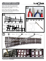
2a 15 14 3 5
9
11
6
43101615
2b
7a 8b
7b8a
(DE) Zweiggleis• (GB) branch line
(FR) voie divergentes • (CZ) přímá kolej
(PL) toru zwrotnego
(DE) Stammgleis • (GB) main line
(FR) voie principale
(CZ) odbočná kolej
(PL) toru zasadniczego
4510 11 15
+ + ++
1
22
23
1
(DE) EW 15° rechts, Bausatz • (GB) right points kit 15°
(FR) EW 15° droite, Kit • (CZ) EW 15° pravá, stavebnice
(PL) Rozjazd EW 15° prawy, Zestaw
i1
i2
i3
i43
2b
2a
15
2 3

www.tillig.com
www.facebook.com/tilligbahn
368301 / 22.08.2019
– 2 –
Güterwagen
Bausatz EW 1 • Kit EW 1
Stavebnice EW 1 • Zestaw EW 1
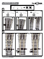
2a 2b 3
1 2 3
10 11
13
11
10
13
12
12 13
1.
1 2
12
2.
3.
1
i4
i4i4
2
3
7b7a
8a8b

www.tillig.com
www.facebook.com/tilligbahn
368301 / 22.08.2019
– 3 –
Güterwagen
Bausatz EW 1 • Kit EW 1
Stavebnice EW 1 • Zestaw EW 1
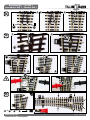
3
5
34
15 15
14
16
116
2
4
66
4
5
123
5
4511 14
+ + +

www.tillig.com
www.facebook.com/tilligbahn
368301 / 22.08.2019
– 4 –
Güterwagen
Bausatz EW 1 • Kit EW 1
Stavebnice EW 1 • Zestaw EW 1
(DE) ACHTUNG! Weichenbausätze sind mechanische Spielwaren. Ihr Gebrauch birgt Verletzungsgefahren an scharangen Teilen. Für ihre Montage sind
spezielle Fergkeiten notwendig.
Nicht geeignet für Kinder unter 14 Jahren wegen abnehmbarer und verschluckbarer Kleinteile und Verletzungsgefahr durch funkonsbedingte scharfe Ecken und Kanten.
Dieses Produkt darf am Ende seiner Nutzungsdauer nicht über den normalen Hausmüll entsorgt werden, sondern muss an einem Sammelpunkt für das Recycling von
elektrischen und elektronischen Geräten abgegeben werden. Bie fragen Sie bei Ihrem Händler oder der Gemeindeverwaltung nach der zuständigen Entsorgungsstelle.
(GB) ATTENTION! Turnout kits are mechanical toys. Their use poses risks of injury at sharp-edged parts. special skills are required for their assembly.
Not suitable for children under 14 years due to danger of swallowing removable small parts and risk of injury on account of unavoidable sharp corners and edges.
When this product comes to the end of its useful life, you may not dispose of it in the ordinary domesc waste but must take it to your local collecon point for recycling
electrical and electronic equipment. If you dont`t know the locaon of your nearest disposal centre please ask your retailer or the local council oce.
(FR) ATTENTION! Kits de commutateur sont des jouets mécaniques. Leur ulisaon implique le risque de blessures sur les pièces à arêtes vives. Des compéten-
ces parculières sont nécessaires pour leur installaon.
Ne convient pas aux enfants de moins de 14 ans d’âge en raison de détachables petes pièces qui peuvent être avalées et les blessures causées par les bords et coins pointus
fonconnelles. Ce produit doit être éliminé à la n de sa vie ule au-delà les ordures ménagères, mais doit être remis à un point de collecte pour le recyclage des équipements
électriques et électroniques. Demandez à votre revendeur ou les administraons locales pour l’éliminaon responsable.
(CZ) POZOR! Stavebnice výhybky je mechanická hračka. Chraňte se před poraněním při montáži ostrých dílů. Na montáž je potřeba být zručný.
Nevhodné pro dě do 14 Iet kvůli nebezpečí spolknutí malých součastí a nebezpečí poraneni od nezbytných ostrých rohů a okrajů. Tento produkt nesmi být na konci svého
užívání zlikvidován jako běžný domovní odpad, ale musí být zlikvidován např. ve sběrném dvoře. Prosím zeptejte se vašeho obchodníka, popř. na svém obecním úřadě na
vhodný způsob likvidace elektrických částí tohoto výrobku.
(PL) UWAGA! Zestawy do montażu rozjazdów są zabawkami mechanicznymi. W trakcie ich używania istnieje niebezpieczeństwo skaleczenia się ostrymi częś-
ciami. Montaż rozjazdów wymaga specjalnych umiejętności precyzyjnej pracy ręcznej.
Nieodpowiednie dla dzieci poniżej 14 roku życia z uwagi na niebezpieczeństwo połknięcia i zadławienia się drobnymi częściami oraz możliwość skaleczenia się ostrymi
końcówkami i krawędziami części funkcyjnych. Produkty oznaczone przekreślonym pojemnikiem po zakończeniu użytkowania nie mogą być usuwane razem z normalnymi
odpadami domowymi, lecz muszą być przekazywane do punktu zbierania i recyklingu urządzeń elektrycznych i elektronicznych. Dzięki recyklingowi pomagają Państwo
skutecznie chronić środowisko naturalne. Prosimy zwrócić się do specjalistycznego sklepu lub do odpowiedniego urzędu w Państwa okolicy, aby dowiedzieć się, gdzie jest
najbliższy punkt recyklingu urządzeń elektrycznych i elektronicznych.
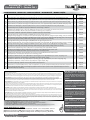
EINZELTEILLISTE • PARTS LIST • LISTE DES PIÈCES • SEZNAM DíLÙ • WYKAZ CZĘŚKI
(DE) Bezeichnung • (GB) Description • (FR) Désignation • (CZ) Název • (PL) Nazwa części Pc. Art.-Nr. / Prod.
no. / N°art. / Kat.č
1(DE) Schwellenband, links • (GB) Sleepe strip, le • (FR) Bande de seuil, gauche • (CZ) Pražcové lože, levé • (PL) Podkład torowy, lewy 1329611
(DE) Schwellenband, rechts • (GB) Sleepe strip, right • (FR) Bande de seuil, droite • (CZ) Pražcove lože, pravé • (PL) Podkład torowy, prawy 1329601
2(DE) Strombrücke, lang • (GB) Current bridge, long • (FR) Pont de force, long • (CZ) Vodivá spojka, dlouhá • (PL) Mostek elektryczny, długi 2339540
3(DE) Strombrücke, kurz • (GB) Current bridge, short • (FR) Pont de force, court • (CZ) Vodivá spojka, krátká • (CZ) Mostek elektryczny, krótki 2339490
4(DE) Mielschiene Stammgleis, L=30,00 mm • (GB) Centre rail, main line, L=30,00 mm • (FR) Rail du centre, piste principale
(CZ) Střední kolej rovná, L=30,00 mm • (PL) Szyna środkowa toru zasadniczego, L=30,00 mm
1388251
5(DE) Mielschiene Zweiggleis, geb., L=30,5 mm • (GB) Centre rail, branch line, curved, L=30,5 mm • Rail du centre, branche
(CZ) Střední kolej odbočná, L=30,5mm • (PL) Szyna środkowa toru zwrotnego, łuk., L=30,50 mm
1388281
6(DE) Drehzapfen • (GB) Pivot • (FR) Axe de pivotement • (CZ) Otočný čep • (PL) Czop obrotowy 2392790
7a (DE) Zunge Weiche links, gerade, Stammgleis • (GB) Blade points rail le, straight, branch line
(FR) Aiguille de l’aiguillage gauche, voie principale • (CZ) Jazyk levé výhybky, rovný, přímá kolej • (PL) Iglica rozjazdu lewego, prosta, tor zasadniczy
1353921
7b (DE) Zunge Weiche links, gebogen, Zweiggleis • (GB) Blade points rail le, curved, main line • (FR) Aiguille de l’aiguillage gauche, voie divergentes
(CZ) Jazyk levé výhybky, obloukovitý, odbočná kolej • (PL) Iglica rozjazdu lewego, łukowa, tor zwrotny
1353922
8a (DE) Zunge Weiche rechts, gerade, Stammgleis • (GB) Blade points rail right, straight, branch line
(FR) Aiguille de l’aiguillage doite, voie principale • (CZ) Jazyk pravé výhybky, rovný, přímá kolej • (PL) Iglica rozjazdu prawego, prosta, tor zasadniczy
1353951
8b (DE) Zunge Weiche rechts, gebogen, Zweiggleis • (GB) Blade points rail right, curved, main line • (FR) Aiguille de l’aiguillage droite,
voie divergentes • (CZ) Jazyk pravé výhybky, obloukovitý, odbočná kolej • (PL) Iglica rozjazdu prawego, łukowa, tor zwrotny
1353952
9(DE) Stellschwelle • (GB) Switching sleeper • (FR) Point seuil • (CZ) Přestavný pražec • (PL) Podkład nastawczy 1328260
10 (DE) Außenschiene Zweiggleis, gebogen • (GB) Outer rail, main line, curved • (FR) Morceau de branche: pliés
(CZ) Vnější kolejnice odbočná, oblouková • (PL) Szyna zewnętrzna toru zwrotnego, łukowa
1388087
11 (DE) Außenschiene Stammgleis, gerade • (GB) Outer rail, branch line, straight • (FR) Morceau de branche: droit
(CZ) Vnější kolejnice rovná • (PL) Szyna zewnętrzna toru zasadniczego, prosta
1388085
12 (DE) Adapter für Weichenantrieb, rund • (GB) Adapter for operang gear, round • (FR) Adaptateur pour moteur d’aiguillage: rond
(CZ) Adaptér pro přestavník, s kulatým otvorem • (PL) Adapter do napędu rozjazdu, okrągły
1329630
13 (DE) Adapter für Weichenantrieb, lang • (GB) Adapter for operang gear, long • (FR) Adaptateur pour moteur d’aiguillage: long
(CZ) Adaptér pro přestavník, s ovalným otvorem • (PL) Adapter do napędu rozjazdu, długi
1329650
14 (DE) Herzstück • (GB) Frog • (FR) Pièce centrale • (CZ) Srdcovka • (PL) Krzyżownica 1354160
15 (DE) Endschiene, L= 28,3 mm • (GB) End rail, L= 28,3 mm • (FR) Rail n, L= 28,3 mm • (CZ) Koncová kolej • (PL) Szyna końcowa, L=28,3 mm 2388211
16 (DE) Strombrücke Herzstück • (GB) Current bridge frog • (FR) Pont de courant pour le pièce centrale • (CZ) Vodivá spojka pro srdcovku
(PL) Mostek elektryczny krzyżownicy
1391281
TILLIG Modellbahnen GmbH
Promenade 1, 01855 Sebnitz • Tel.: +49 (0)35971 / 903-45 • Fax: +49 (0)35971 / 903-19
0-3
0-3
(DE) Technische Änderungen vorbehalten! Bei Reklamaonen wenden Sie sich bie an Ihren Fachhändler.
(GB) Subject to technical changes! Please contact your dealer if you have any complaints.
(FR) Sous réserve de modicaons techniques! Pour toute réclamaon, adressez-vous à votre revendeur.
(CZ) Technické změny vyhrazeny! Při reklamaci se obraťte na svého obchodníka.
(PL) Zastrzega się możliwość zmian technicznych! W przypadku reklamacji prosimy zgłaszać się do specjalistycznego sprzedawcy.
(DE) Hotline Kundendienst • (GB) Hotline customer service • (FR) Services à la clientèle Hotline
(CZ) Hotline Zákaznické služby • (PL) Biuro Obsługi Klienta: www.llig.com/Service_Hotline.html
(DE) Bitte vergleichen Sie vor dem
Montagebeginn die vorhandenen
Teile mit der Bauanleitung. Reklama-
tionen montierter oder teilmontierter
Bausätze können nicht anerkannt
werden!
(GB) Before starting to assemble,
please check that all parts are there
by comparing them with the building
instructions. Complaints about as-
sembled or partially assembled kits
cannot be accepted!
(FR) Avant de commencer le monta-
ge, comparer les pièces disponibles
avec celles gurant dans les instruc-
tions de service. Nous ne pouvons
pas accepter les réclamations con-
cernant des kits montés ou partielle-
ment montés.
(CZ) Porovnejte prosím před montáží
dané součástky s návodem. Rekla-
mace smontovaných či částečně
smontovaných dílů nebude brána v
potaz!
(PL) Przed rozpoczęciem montażu
należy porównać otrzymane części
z instrukcją montażu. Reklamacje
złożonych lub częściowo złożonych
zestawów nie będą uznawane!
-
 1
1
-
 2
2
-
 3
3
-
 4
4


TILLIG BAHN 83432 Bedienungsanleitung
- Typ
- Bedienungsanleitung
- Dieses Handbuch eignet sich auch für
in anderen Sprachen
- English: TILLIG BAHN 83432 Owner's manual
- français: TILLIG BAHN 83432 Le manuel du propriétaire
- polski: TILLIG BAHN 83432 Instrukcja obsługi
Verwandte Artikel
-
TILLIG BAHN 83437 Bedienungsanleitung
-
-
-
-
-
-
-
-
-