
Güterwagen
www.tillig.com / www.facebook.com/tilligbahn 368553 / 18.03.2016
H0-ELITE-WEICHE, EW 6
H0-ELITE-POINT, EW 6 Güterwagen
– 1 –
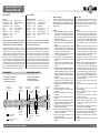
Stückliste:
Schwellenband 1 1 Stück
Schwellenband 2 1 Stück
Außenschiene li. 1 Stück
Außenschiene re. 1 Stück
Zunge li. 1 Stück
Zunge re. 1 Stück
Endschiene li. 1 Stück
Endschiene re. 1 Stück
Flügelschiene li. 1 Stück
Flügelschiene re. 1 Stück
Bauvarianten Construction variations
Art.-Nr. 85445 Art.-no. 85445
Allgemeiner Hinweis:
An allen Profilen sind vor dem Einbau, Fräsrückstände und
Schnittgrate zu entfernen. Die Profilstücke sind entspre-
chend der Weichengeometrie vorzubiegen und an den für
die Stromabnahme vorgesehenen Stellen unten am Schie-
nenfuß zu blanken.
Montage:
1. Aus den Neusilberstreifen werden U-förmige Strom-
brücken gebogen. Diese werden an den entsprechen-
den Schwellen von unten durch das Schwellenrost
gesteckt und je nach Einschubrichtung der Profile
umgebogen. S. 2 Abb. 2 u. 3
2. Die Schwellenroste 1 und 2, beginnend mit dem Wei-
chenanfang Schwellenrost 1, an das vorhandene Gleis
anlegen.
3. Außenschienen vom Weichenausgang her so weit
einschieben, bis das Profil 2 mm am Weichenanfang
über das Schwellenrost hinaus ragt, die Aussparung
am Schienenfuß zeigt dabei zur Gleismitte.
4. Weichenkörper in die gewünschte Form bringen und
mit Stiften oder Reiszwecken fixieren.
5. Die Außenschienen am Weichenausgang mit einem
Überstand von 2 mm zur letzten Schwelle kürzen und
verputzen.
6. Die Flügelschienen nach S. 2 Abb. 4 biegen und an-
schließend in das Schwellenrost bis Anschlag ein-
schieben.
7. Die Hauptspitze des Herzstückes wird in der Regel durch
die Endschiene des Stammgleises gebildet. Die
Endschiene Stammgleis ggf. vorbiegen und in das
Schwellenrost einschieben, die Profilspitze hat einen
Abstand von 24,5 mm zum Ende der Flügelschiene.
S. 2 Abb. 5
8. Die Endschiene Zweiggleis vorbiegen und so weit
einschieben, dass sich mit der Hauptspitze auf der
Zweiggleisseite eine durchgängige Fahrkante ergibt.
9. Die Endschienen mit 2 mm Überstand zu der letzten
Schwelle kürzen.
10. Stellschwelle in das Stellfach einschieben.
11. An den Zungenspitzen leichte Radien anbringen.
S. 2 Abb. 6
12. Die Zungenhaken senkrecht 90° nach unten biegen.
S. 2 Abb. 6
13. Weichenzungen entsprechend der Weichenform ggf.
vorbiegen.
14. Die Weichenzungen auf das Schwellenrost auflegen,
den Haken in das Loch der Stellschwellen einhängen
und das Zungenende entsprechend „kürzen”
15. Einschieben der Zungenschienen und die Zungenha-
ken in die Stellschwelle einhängen.
16. Weiche von den Gleisen (S. 2 Abb. 2) abziehen und
die Enden der Zungenhaken unterhalb der Stell-
schwelle um 90° zurück biegen.
17. Kabel zur Stromversorgung an dem Herzstück und
den Flügelschienen anlöten.
18. Weiche einbauen, Profile ausrichten, Einschieben der
Radlenker.
General notice:
Prior to installing anything onto the profiles (structural sha-
pes), metal-shavings and cutting-burrs are to be removed.
The profile pieces are to be bent in proportion to the point
geometry and shined at the points intended for power con-
tact underneath on the foot of the rail.
Assembly:
1. A U-shaped electric bond is to be bent from the ni-
ckel-silver strips. These are then stuck through at the re-
spective sleepers (cross-ties) from underneath through
the flex sleepers and bent depending on the insertion
direction of the profile. (see page 2 figures 2 and 3)
2. Lay down the flex sleepers 1 and 2, beginning with the
start of the point flex sleeper 1, onto the pre-existing
track.
3. Push the outer rails, from the standpoint of the start of
the point, until the profile sticks out 2mm over the flex
sleeper at the start of the point, while the recess clea-
rance points in the direction of the middle of the track.
4. Bend the sleeper-bodies into the desired form and at-
tach them with either pins or thumbtacks.
5. Shorten and clean the outer rail at the start of the
point with an excess of 2mm in the direction of the last
sleeper.
6. Bend the wing rails according to page 2 figure 4 and
then insert into the flex sleepers to the stop point.
7. The main point of the frog is normally formed by the
end rail of the main track. Bend out the end rail, or the
main track if necessary, and insert into the flex sleeper;
the profile point should have a separation of 24.5 mm
from the end of the wing rail. (see page 2 figure 5)
8. Bend out the end rail branch track and insert so far that
a continuous riding edge is formed with the main point
on the branch track side.
9. Shorten the end rails with 2 mm excess length to the
last sleeper.
10. Insert the directional cross-tie (sliding sleeper) into the
space.
11. Apply light radii onto the tip of the tongue.
(see page 2 figure 6)
12. Bend the tongue hooks vertically 90° downwards.
(see page 2 figure 6)
13. If necessary, bend the point tongue up to correspond
with the form of the point.
14. Lay down the point tongue onto the flex sleeper, hook
the hook into the hole of the directional cross-tie (sli-
ding sleeper) and cut the end of the tongue to length
respectively.
15. Push the tongue rail in and hook the tongue hook into
the directional cross-tie (sliding sleeper).
16. Pull the point up from the tracks (see page 2 figure 2)
and bend back the ends of the tongue hook by 90° un-
derneath the directional cross-tie (sliding sleeper).
17. Solder the power supply cable onto the frog and the
wing rails.
18. Embed the point, align the profile and push the wheel
guide in.
1. Außenbogenweichen links/rechts
2. Einfache Weichen links/rechts
3. Innenbogenweiche links/rechts
1. Outer curved points left/right
2. Simple points left/right
3. Inner curved points left/right
Stellschwelle (bein- 1 x
haltet in GS Stelleinheit)
Radlenker 2 x
Strombrücken 4 x
Isolierschienenverb. 2 x
Schieneverb. brüniert 2 x
GS Stelleinheit 1 x
BAL 1 x
Replacement parts list:
Sleeper band 1 1 piece
Sleeper band 2 1 piece
Outer rail (l.) 1 piece
Outer rail (r.) 1 piece
Tongue (l.) 1 piece
Tongue (r.) 1 piece
End rail (l.) 1 piece
End rail (r.) 1 piece
Wing rail (l.) 1 piece
Wing rail (r.) 1 piece
Directional cross-tie 1 x
(included in GS height
adjustment unit)
Wheel guide 2 x
Electric bonds 4 x
Insulating rail joiners 2 x
Rail joiners bronzed 2 x
GS height adjustment unit 1 x
BAL 1 x
Benötigtes Werkzeug: Gleisschneider oder Minibohrma-
schine mit Trennscheibe, Schlüsselfeilen, Flachzange, Löt-
kolben, Reißzwecken, Seitenschneider, Messschieber.
Für das Standardsortiment der Eliteweichen kann als Bau-
grundlage die Planungsmappe H0-Elite Art.-Nr. 09620
verwendet werden. Für den Bau von Bogenweichen mit
individueller Geometrie bieten die Weichen mit dem Flex-
steg-Schwellenverbinder die Möglichkeit, „Ihre“ gewünschte
Weichenform zu realisieren. Dabei sollte beachtet werden,
dass ein Überbiegen als auch Überstrecken der Schwellen-
roste schon aus Gründen einer vorbildgerechten Darstellung
vermieden wird. Gestatten Sie noch einen Hinweis: Arbeiten
Sie ohne Zeitdruck und genau. Das Ergebnis, eine Weiche,
die hervorragende Fahreigenschaften bietet und optisch jede
Gleisanlage aufwertet, wird Ihnen viel Freude bereiten.
Tools required: Track cutter or mini-drill with cut-off wheel,
needle files, flat-nosed pliers, soldering iron, thumbtacks,
side-cutting pliers, sliding calliper.
For the standard assortment of Elite-Points, the planning fol-
der H0-Elite Art.-No. 09620 can be used as a basis for con-
struction. To construct curved points (turnouts) with their
own individual geometry, the points offer, with their flex-base
sleeper connectors, the possibility to set up “your” own desi-
red point (turnout) form. However, you should be careful to
avoid over-bending or over-stretching the flex sleepers to assu-
re exemplary construction. And allow us one more suggestion
here: it is better to work without time constraints, but with
precision. The finished product of a point (turnout) that offers
exceptional handling characteristics and optically enhances
any track system, will provide you with all the more enjoyment.
368553-S.1
10.01.2011
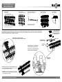
Außenschiene
Zweiggleis/
Outer rail
Branch track
Außenschiene
Stammgleis/
Outer rail
Main track
Weichenzunge li/
Point tongue l.
Weichenzunge re/
Point tongue r.
Strombrücke/
Electric bond
Strombrücke/
Electric bond
Radlenker/
Wheel guide
Radlenker/
Wheel guide
Strombrücke/
Electric bond
Flügelschiene/
Wing rail
Flügelschiene/
Wing rail
Endschiene li/
End rail l.
Endschiene re/
End rail r.
Lage der Strombrücke
unter dem Profil
Art.-Nr.: 85445 Art. no. 85445
Für das Standardsortiment der Eliteweichen kann als Baugrundlage die Planungsmappe H0-Elite Art.-Nr. 09620 verwendet werden. Für den Bau von
Bogenweichen mit individueller Geometrie bieten die Weichen mit dem Flexsteg-Schwellenverbinder die Möglichkeit, „Ihre“ gewünschte Weichenform zu
realisieren. Dabei sollte beachtet werden, dass ein Überbiegen als auch Überstrecken der Schwellenroste schon aus Gründen einer vorbildgerechten
Darstellung vermieden wird. Gestatten Sie noch einen Hinweis: Arbeiten Sie ohne Zeitdruck und genau. Das Ergebnis, eine Weiche, die hervorragende
Fahreigenschaften bietet und optisch jede Gleisanlage aufwertet, wird Ihnen viel Freude bereiten.
For the standard assortment of Elite-Points, the planning folder H0-Elite Art.-No. 09620 can be used as a basis for construction. To construct curved points
(turnouts) with their own individual geometry, the points offer, with their flex-base sleeper connectors, the possibility to set up “your” own desired point
(turnout) form. However, you should be careful to avoid over-bending or over-stretching the flex sleepers to assure exemplary construction. And allow us
one more suggestion here: it is better to work without time constraints, but with precision. The finished product of a point (turnout) that offers exceptional
handling characteristics and optically enhances any track system, will provide you with all the more enjoyment.
Replacement parts list:
Sleeper band 1 1 piece
Sleeper band 2 1 piece
Outer rail (l.) 1 piece
Outer rail (r.) 1 piece
Tongue (l.) 1 piece
Tongue (r.) 1 piece
End rail (l.) 1 piece
End rail (r.) 1 piece
Stückliste:
Schwellenband 1 1 Stück
Schwellenband 2 1 Stück
Außenschiene li 1 Stück
Außenschiene re 1 Stück
Zunge li 1 Stück
Zunge re 1 Stück
Endschiene li 1 Stück
Endschiene re 1 Stück
Wing rail (l.) 1 piece
Wing rail (r.) 1 piece
Directional cross-tie 1 x
(included in GS height
adjustment unit)
Wheel guide 2 x
Electric bonds 4 x
Insulating rail joiners 2 x
Rail joiners bronzed 2 x
GS height adjustment unit 1 x
BAL 1 x
Flügelschiene li 1 Stück
Flügelschiene re 1 Stück
Stellschwelle (bein- 1 x
haltet in GS Stelleinheit)
Radlenker 2 x
Strombrücken 4 x
Isolierschienenverb. 2 x
Schieneverb. brüniert 2 x
GS Stelleinheit 1 x
BAL 1 x
Benötigtes Werkzeug: Gleisschneider oder Minibohrmaschine mit Trennscheibe, Schlüsselfeilen, Flachzange, Lötkolben, Reißzwecken,
Seitenschneider, Messschieber
Tools required: Track cutter or mini-drill with cut-off wheel, needle files, flat-nosed pliers, soldering iron, thumbtacks, side-cutting pliers,
sliding calliper
Bauvarianten Construction variations
1. Außenbogenweichen links/rechts
2. Einfache Weichen links/rechts
3. Innenbogenweiche links/rechts
1. Outer curved points left/right
2. Simple points left/right
3. Inner curved points left/right
Allgemeiner Hinweis:
An allen Profilen sind vor dem Einbau, Fräsrückstände und Schnittgrate zu entfernen. Die Profilstücke sind entsprechend der Weichengeometrie
vorzubiegen und an den für die Stromabnahme vorgesehenen Stellen unten am Schienenfuß zu blanken.
Montage:
1. Aus den Neusilberstreifen werden U-förmige Strombrücken gebogen. Diese werden an den entsprechenden Schwellen von unten durch
das Schwellenrost gesteckt und je nach Einschubrichtung der Profile umgebogen. S. 2 Abb. 2 u. 3
2. Die Schwellenroste 1 und 2, beginnend mit dem Weichenanfang Schwellenrost 1, an das vorhandene Gleis anlegen.
3. Außenschienen vom Weichenausgang her so weit einschieben, bis das Profil 2 mm am Weichenanfang über das Schwellenrost hinaus ragt,
die Aussparung am Schienenfuß zeigt dabei zur Gleismitte.
4. Weichenkörper in die gewünschte Form bringen und mit Stiften oder Reiszwecken fixieren.
5. Die Außenschienen am Weichenausgang mit einem Überstand von 2 mm zur letzten Schwelle kürzen und verputzen.
6. Die Flügelschienen nach S. 2 Abb. 4 biegen und anschließend in das Schwellenrost bis Anschlag einschieben.
7. Die Hauptspitze des Herzstückes wird in der Regel durch die Endschiene des Stammgleises gebildet. Die Endschiene Stammgleis ggf. vorbiegen
und in das Schwellenrost einschieben, die Profilspitze hat einen Abstand von 24,5 mm zum Ende der Flügelschiene. S. 2 Abb.5
8. Die Endschiene Zweiggleis vorbiegen und so weit einschieben, dass sich mit der Hauptspitze auf der Zweiggleisseite eine durchgängige
Fahrkante ergibt.
9. Die Endschienen mit 2 mm Überstand zu der letzten Schwelle kürzen.
10. Stellschwelle in das Stellfach einschieben.
11. An den Zungenspitzen leichte Radien anbringen. S. 2 Abb. 6
12. Die Zungenhaken senkrecht 90° nach unten biegen. S. 2 Abb. 6
13. Weichenzungen entsprechend der Weichenform ggf. vorbiegen.
14. Die Weichenzungen auf das Schwellenrost auflegen, den Haken in das Loch der Stellschwellen einhängen und das Zungenende entsprechend
„kürzen”.
15. Einschieben der Zungenschienen und die Zungenhaken in die Stellschwelle einhängen.
16. Weiche von den Gleisen (S. 2 Abb. 2) abziehen und die Enden der Zungenhaken unterhalb der Stellschwelle um 90° zurück biegen.
17. Kabel zur Stromversorgung an dem Herzstück und den Flügelschienen anlöten.
18. Weiche einbauen, Profile ausrichten, Einschieben der Radlenker.
Stellschwelle/
Directional cross-tie
(sliding sleeper)
General notice:
Prior to installing anything onto the profiles (structural shapes), metal-shavings and cutting-burrs are to be removed. The profile pieces are to be bent in
proportion to the point geometry and shined at the points intended for power contact underneath on the foot of the rail.
Assembly:
1. A U-shaped electric bond is to be bent from the nickel-silver strips. These are then stuck through at the respective sleepers (cross-ties) from
underneath through the flex sleepers and bent depending on the insertion direction of the profile (see p. 2 figures 2 and 3)
2. Lay down the flex sleepers 1 and 2, beginning with the start of the point flex sleeper 1, onto the pre-existing track.
3. Push the outer rails, from the standpoint of the start of the point, until the profile sticks out 2mm over the flex sleeper at the start of the point,
while the recess clearance points in the direction of the middle of the track.
4. Bend the sleeper-bodies into the desired form and attach them with either pins or thumbtacks.
5. Shorten and clean the outer rail at the start of the point with an excess of 2mm in the direction of the last sleeper.
6. Bend the wing rails according to page 2 figure 4 and then insert into the flex sleepers to the stop point.
7. The main point of the frog is normally formed by the end rail of the main track. Bend out the end rail, or the main track if necessary, and insert
into the flex sleeper; the profile point should have a separation of 24.5 mm from the end of the wing rail. (see page 2 figure 5)
8. Bend out the end rail branch track and insert so far that a continuous riding edge is formed with the main point on the branch track side.
9. Shorten the end rails with 2 mm excess length to the last sleeper.
10. Insert the directional cross-tie (sliding sleeper) into the space
11. Apply light radii onto the tip of the tongue see page 2 figure 6
12. Bend the tongue hooks vertically 90° downwards see page 2 figure 6
13. If necessary, bend the point tongue up to correspond with the form of the point.
14. Lay down the point tongue onto the flex sleeper, hook the hook into the hole of the directional cross-tie (sliding sleeper) and cut the end of the
tongue to length respectively.
15. Push the tongue rail in and hook the tongue hook into the directional cross-tie (sliding sleeper).
16. Pull the point up from the tracks (see page 2 figure 2) and bend back the ends of the tongue hook by 90° underneath the directional cross-tie
(sliding sleeper).
17. Solder the power supply cable onto the frog and the wing rails.
18. Embed the point, align the profile and push the wheel guide in.
Location of the electric bond
under the profile
H0-ELITE-WEICHE, EW 6 H0-ELITE-POINT, EW 6

Güterwagen
www.tillig.com / www.facebook.com/tilligbahn 368553 / 18.03.2016
H0-ELITE-WEICHE, EW 6
H0-ELITE-POINT, EW 6 Güterwagen
– 2 –
.
368552-S.2
01.12.2009
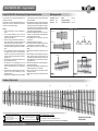
Abb. 5 Herzstückspitze/
Figure 5 Tip of the frog:
24,5 mm
Abb. 6 Zungenhaken/
Figure 6 Tongue hook:
Radius
90°
Zur Ausgestaltung des Weichenumfeldes liegen der Weiche noch weitere Teile der Weichenstelleinrichtung bei, die laut Zeichnung angebracht werden können.
For the design of the immediate surrounding area of the turnout point (switch), there are additional components other than the turnout point arrangement itself, which can be attached as well, according to the drawing.
Stelleinrichtung im montierten Zustand/
Turnout (point) arrangement in assembled condition
Umlenkrollenabdeckung,
wahlweise Abdeckung/
Diversion pulley covering,
Covering is optional
Rahmen/
Frame
Seilzugabdeckung/
Rope pulley covering
Abdeckung/
Covering
Kleine Abdeckungen – ins Schwellenband
beidseitig eingesetzt (Ansicht von unten)
Small coverings – set into the sleeper band
on both sides (view from underneath)
Alternativ: Stelleinrichtung auf gegenüberliegender Seite mit
flacher Seilrollenabdeckung, Seilzugkanal und kleiner Kasten
können gegeneinander getauscht werden
Alternative: Turnout (point) arrangement on the opposing
side with rope pulley covering, rope pull channel and small
box can be exchanged for one another.
Einschubrichtung Profile/
Insertion direction profile
Abb. 2 Draufsicht/
Figure 2 Top view:
(*)
(*)
(*) Bitte nach unten biegen!/
(*) Please bend in a downward direction!
Abb. 3 Unteransicht/
Figure 3 View from underneath:
Abb. 4 Schablone – Flügelschiene rechts/
Figure 4 Template - wing rail right:
M 1:1
(6,4°)
4°
(Flügelschiene links = Spiegelbild)/
(wing rail left = mirror image)
Detailansicht/
Detailed view
Art.-Nr.: 85435
Art. no. 85435
H0-ELITE-WEICHE, EW 5
H0-ELITE-POINT, EW 5
Zur Ausgestaltung des Weichenumfeldes liegen der Weiche noch weitere Teile der Weichenstelleinrichtung bei, die laut Zeichnung angebracht werden können.
For the design of the immediate surrounding area of the turnout point (switch), there are additional components other than the turnout point arrangement
itself, which can be attached as well, according to the drawing.
Umlenkrollenabdeckung,
wahlweise Abdeckung/
Diversion pulley covering,
Covering is optional
Rahmen / Frame
Seilzugabdeckung/
Rope pulley covering
Alternativ: Stelleinrichtung auf gegenüberliegender Seite mit
flacher Seilrollenabdeckung, Seilzugkanal und kleiner Kasten
können gegeneinander getauscht werden.
Alternatively: Turnout (point) arrangement on the opposing
side with rope pulley covering, rope pull channel and small box
can be exchanged for one another.
Abdeckung/
Covering
Detailansicht/
Detailed view
Stelleinrichtung im montierten Zustand/
Turnout (point) arrangement in assembled condition
Kleine Abdeckungen – ins Schwellenband
beidseitig eingesetzt (Ansicht von unten)
Small coverings – set into the sleeper band
on both sides (view from underneath)
368553-S.2
10.01.2011
Abb. 5 Herzstückspitze/
Figure 5 Tip of the frog:
24,5 mm
Abb. 6 Zungenhaken/
Figure 6 Tongue hook:
Radius
90°
Zur Ausgestaltung des Weichenumfeldes liegen der Weiche noch weitere Teile der Weichenstelleinrichtung bei, die laut Zeichnung angebracht werden können.
For the design of the immediate surrounding area of the turnout point (switch), there are additional components other than the turnout point arrangement itself, which can be attached as well, according to the drawing.
Stelleinrichtung im montierten Zustand/
Turnout (point) arrangement in assembled condition
Umlenkrollenabdeckung,
wahlweise Abdeckung/
Diversion pulley covering,
Covering is optional
Rahmen/
Frame
Seilzugabdeckung/
Rope pulley covering
Abdeckung/
Covering
Kleine Abdeckungen – ins Schwellenband
beidseitig eingesetzt (Ansicht von unten)
Small coverings – set into the sleeper band
on both sides (view from underneath)
Alternativ: Stelleinrichtung auf gegenüberliegender Seite mit
flacher Seilrollenabdeckung, Seilzugkanal und kleiner Kasten
können gegeneinander getauscht werden
Alternative: Turnout (point) arrangement on the opposing
side with rope pulley covering, rope pull channel and small
box can be exchanged for one another.
Einschubrichtung Profile/
Insertion direction profile
Abb. 2 Draufsicht/
Figure 2 Top view:
(*)
(*)
(*) Bitte nach unten biegen!/
(*) Please bend in a downward direction!
Abb. 3 Unteransicht/
Figure 3 View from underneath:
Abb. 4 Schablone – Flügelschiene rechts/
Figure 4 Template - wing rail right:
M 1:1
(6,4°)
4°
(Flügelschiene links = Spiegelbild)/
(wing rail left = mirror image)
Detailansicht/
Detailed view
Art.-Nr.: 85445 Art. no. 85445
H0-ELITE-WEICHE, EW 6 H0-ELITE-POINT, EW 6

Güterwagen
www.tillig.com / www.facebook.com/tilligbahn 368553 / 18.03.2016
Güterwagen
– 3 –
An den Profilen sind vor dem Einbau Fräsrückstände und Schnittgrate zu entfernen.
Die Profilstücke sind entsprechend der Weichengeometrie vorzubiegen und an den für die Stromabnahme vorgesehenen Stellen unten am
Schienenfuß zu blanken.
Montage:
1. Trennen der Schwellenroste 1 und 2 wie in Abb. 1 a dargestellt.
2. Um eine optimale Verbindung zu erzielen, müssen die Schwellen an den späteren Klebeflächen mit einer Feile plan gefeilt werden. Abb. 2 a
3. Die durch das Trennen entstandenen Schwellenroste 1.1 und 2.1 durch Erwärmen mit einem Fön auf die benötigte Länge strecken,
die Vorlage dient dazu als Schablone.
4. Die einzelnen Schwellenroste werden nun durch Kleben miteinander verbunden.(empfohlener Kleber: Pattex Blitzkleber).
5. Aus den Neusilberstreifen werden U-förmige Strombrücken gebogen. Diese werden an den entsprechenden Schwellen von unten
durch die Schwellenroste gesteckt und in die spätere Einschubrichtung der Profile umgebogen. Abb. 2 u. 3
6. Das Schwellenrost nach der Schablone ausrichten und mit Stiften oder Reißzwecken fixieren.
7. Die Außenschienen vom Weichenausgang her so weit einschieben, bis die Ausklinkung am Schienenfuß auf der Innenseite des
Schienenprofils an der 2. Schwelle liegt. Abb. 3 a
8. Die Außenschienen am Weichenausgang mit einem Überstand von 2 mm zur letzten Schwelle kürzen und die Schnittkante verputzen.
9. Die Flügelschienen nach Abb. 4 biegen und anschließend in das Schwellenrost bis an den Stoß der Doppelschwelle einschieben. Abb. 4 a
10. Die Hauptspitze des Herzstückes wird in der Regel durch die Endschiene des Stammgleises gebildet.
Die Endschiene Stammgleis entsprechend der gewählten Weichengeometrie vorbiegen und in das Schwellenrost einschieben, die
Profilspitze hat einen Abstand von 28,8 mm bis an den Schienenstoß der Flügelschiene. Abb. 3 a
11. Die Endschiene Zweiggleis vorbiegen und so weit einschieben, dass sich mit der Hauptspitze auf der Zweiggleisseite eine durchgängige
Fahrkante ergibt.
12. Die Endschienen mit 2 mm Überstand zu der letzten Schwelle kürzen.
13. Stellschwelle in das Stellfach einschieben.
14. An den Zungenspitzen leichte Radien anbringen und den Schienenkopf nach vorn auslaufen lassen. Abb. 6
15. Die Zungenhaken senkrecht 90° nach unten biegen. Abb. 6
16. Weichenzungen entsprechend der Weichenform vorbiegen.
17. Die Weichenzungen auf das Schwellenrost auflegen, der Haken muss dabei über dem jeweils äußeren Loch der Stellschwellen liegen, die
Weichenzungen werden jetzt an der Doppelschwelle mit 0,3 mm Zwischenraum zur Flügelschiene abgeschnitten.
18. Einschieben der Zungenschienen und die Zungenhaken in die Stellschwelle einhängen.
19. Weiche abziehen und die Enden der Zungenhaken unterhalb der Stellschwelle um 90° zurück biegen.
20. Kabel zur Stromversorgung an dem Herzstück und den Flügelschienen anlöten.
21. Weiche einbauen, Profile ausrichten, Einschieben der Radlenker.
Nicht geeignet für Kinder unter 3 Jahren
wegen abnehmbarer und verschluckbare
Kleinteile und Verletzungsgefahr durch
funktionsbedingte scharfe Ecken und Kanten.
0-3
TILLIG Modellbahnen GmbH
Promenade 1, 01855 Sebnitz
Tel. +49 (0)35971 903-0, www.tillig.com
Dieses Produkt darf am End e seiner Nu tzungsdauer
nicht über den normalen Hausmüll entsorgt werden, sondern
muss an einem Sammelpunkt für das Recycling von elektrischen
und elektronischen Geräten abgegeben werden.
Bitte fragen Sie bei Ihrem Händler oder der Gemeindeverwaltung
nach der zuständigen Entsorgungsstelle.
368553-S.3
10.01.2011
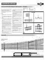
Bausatz H0 Elite EW 6: Bauanleitung für Doppelschwellenweichen Abb. 1 a Abb. 2 a
Abb. 4 aAbb. 3 a
plan feilen
Schwellenrost 2 trennen
trennen
10.
20.
trennen
trennen
Schwellenrost 1
1 1.1 2 2.1
Schablone, Weiche rechts
Ausklinkung 28,8 mm
Weichengeometrie
Einbaulänge: 388 mm
Herzstück: 6,34°
Endwinkel: 6,34°
Radius: 2200 mm
Zweiggleisendneigung: 1:9
Länge gerades Endteil: 145,3 mm
Schablone für linke Weiche:
Siehe Rückseite
Art.-Nr.: 85445
H0-ELITE-WEICHE, EW 6 – Doppelschwelle
H0-ELITE-WEICHE, EW 6 – Doppelschwelle
Dieses Produkt darf am Ende seiner Nutzungsdauer nicht über
den normalen Hausmüll entsorgt werden, sondern muss an
einem Sammelpunkt für das Recycling von elektrischen und elek-
tronischen Geräten abgegeben werden.
Bitte fragen Sie bei Ihrem Händler oder der Gemeindeverwaltung
nach der zuständigen Entsorgungsstelle.
0-3
TILLIG Modellbahnen GmbH
Promenade 1, 01855 Sebnitz
Tel.: +49 (0)35971 / 903-45 Fax: +49 (0)35971 / 903-19
Service-Hotline: unsere aktuellen Hotline-Zeiten finden Sie unter: www.tillig.com
Bausatz H0 Elite EW 6: Bauanleitung für Doppelschwellenweichen
An den Profilen sind vor dem Einbau Fräsrückstände und
Schnittgrate zu entfernen.
Die Profilstücke sind entsprechend der Weichengeometrie vor-
zubiegen und an den für die Stromabnahme vorgesehenen
Stellen unten am Schienenfuß zu blanken.
Montage:
1. Trennen der Schwellenroste 1 und 2 wie in Abb. 1a dar-
gestellt.
2. Um eine optimale Verbindung zu erzielen, müssen die
Schwellen an den späteren Klebeflächen mit einer Feile
plan gefeilt werden. Abb. 2a
3. Die durch das Trennen entstandenen Schwellenroste 1.1
und 2.1 durch Erwärmen mit einem Fön auf die benötigte
Länge strecken, die Vorlage dient dazu als Schablone.
4. Die einzelnen Schwellenroste werden nun durch Kleben
miteinander verbunden (empfohlener Kleber: Pattex Blitz-
kleber).
5. Aus den Neusilberstreifen werden U-förmige Strombrü-
cken gebogen. Diese werden an den entsprechenden
Schwellen von unten durch die Schwellenroste gesteckt
und in die spätere Einschubrichtung der Profile umgebo-
gen. Abb. 2 u. 3
6. Das Schwellenrost nach der Schablone ausrichten und mit
Stiften oder Reißzwecken fixieren.
7. Die Außenschienen vom Weichenausgang her so weit
einschieben, bis die Ausklinkung am Schienenfuß auf der
Innenseite des Schienenprofils an der 2. Schwelle liegt.
Abb. 3a
8. Die Außenschienen am Weichenausgang mit einem Über-
stand von 2 mm zur letzten Schwelle kürzen und die
Schnittkante verputzen.
9. Die Flügelschienen nach Abb. 4 biegen und anschließend
in das Schwellenrost bis an den Stoß der Doppelschwelle
einschieben. Abb. 4a
10. Die Hauptspitze des Herzstückes wird in der Regel durch
die Endschiene des Stammgleises gebildet. Die Endschiene
Stammgleis entsprechend der gewählten Weichengeo-
metrie vorbiegen und in das Schwellenrost einschieben,
die Profilspitze hat einen Abstand von 28,8 mm bis an den
Schienenstoß der Flügelschiene. Abb. 3a
11. Die Endschiene Zweiggleis vorbiegen und so weit einschie-
ben, dass sich mit der Hauptspitze auf der Zweiggleisseite
eine durchgängige Fahrkante ergibt.
12. Die Endschienen mit 2 mm Überstand zu der letzten
Schwelle kürzen.
13. Stellschwelle in das Stellfach einschieben.
14. An den Zungenspitzen leichte Radien anbringen und den
Schienenkopf nach vorn auslaufen lassen. Abb. 6
15. Die Zungenhaken senkrecht 90° nach unten biegen.
Abb. 6
16. Weichenzungen entsprechend der Weichenform vorbie-
gen.
17. Die Weichenzungen auf das Schwellenrost auflegen, der
Haken muss dabei über dem jeweils äußeren Loch der
Stellschwellen liegen, die Weichenzungen werden jetzt an
der Doppelschwelle mit 0,3 mm Zwischenraum zur Flügel-
schiene abgeschnitten.
18. Einschieben der Zungenschienen und die Zungenhaken in
die Stellschwelle einhängen.
19. Weiche abziehen und die Enden der Zungenhaken unter-
halb der Stellschwelle um 90° zurück biegen.
20. Kabel zur Stromversorgung an dem Herzstück und den
Flügelschienen anlöten.
21. Weiche einbauen, Profile ausrichten, Einschieben der Rad-
lenker.
Schablone, Weiche rechts
Weichengeometrie
Einbaulänge: 388 mm
Herzstück: 6,34°
Endwinkel: 6,34°
Schablone für linke Weiche:
Siehe Rückseite
plan feilen
Schwellenrost 2
trennen
trennen
10.
20.
trennen
trennen
Schwellenrost 1
Ausklinkung 28,8 mm
Abb. 1a Abb. 2a
Abb. 3a Abb. 4a
Radius: 2200 mm
Zweiggleisendneigung: 1:9
Länge gerades Endteil: 145,3 mm
0-3
Nicht geeignet für Kinder unter 14 Jahren
wegen abnehmbarer und verschluckbarer
Kleinteile und Verletzungsgefahr durch
funktionsbedingte scharfe Ecken und Kanten.

Güterwagen
www.tillig.com / www.facebook.com/tilligbahn 368553 / 18.03.2016
Güterwagen
– 4 –
Prior to installing anything onto the profiles (structural shapes) metal-shavings and cutting-burrs are to be removed.
The profile pieces are to be bent in proportion to the point geometry and shined at the points intended for power contact underneath on
the foot of the rail.
Assembly:
1. Separation of the flex sleepers 1 and 2 as illustrated in Figure 1a.
2. In order to achieve an optimal connection, the sleepers must be filed with a file on the later glued surface Figure 2a.
3. The flex sleepers 1.1. and 2.1 that emerge from the separation should be heated with a hair-dryer and lengthened to the required
length; the model serves as a template for this purpose.
4. The individual flex sleepers are now to be connected to one another by gluing (recommended glue: Pattex Blitzkleber).
5. A U-shaped electric bond is to be bent from the nickel-silver strips. These are then stuck through at the respective sleepers (cross-ties)
from underneath through the flex sleepers and bent depending on the insertion direction of the profile (see p. 2 figures 2 and 3)
6. Align the flex sleeper according to the template, and attach with pins or thumbtacks.
7. Push in the outer rails so far, from the standpoint of the start of the point, until the recess area at the foot of the rail on the inner side
of the rail profile lies at the second sleeper. Figure 3a
8. Shorten the end rails with 2 mm excess length to the last sleeper and clean the edge of the cut-line.
9. Bend the wing rails according to page 2 figure 4 and then insert into the flex sleepers to the stop point of the double sleeper. Figure 4a
10. The main tip of the frog is normally formed by the end rail of the main track. Bend out the end rail main track according to the desired
point geometry and insert into the flex sleeper; the profile point has a separation of 28.8 mm to the rail joint of the wing rail. Figure 3a
11. Bend out the end rail double track and insert so far that a continuous riding edge is formed with the main point on the branch track side.
12. Shorten the end rails with 2 mm excess length to the last sleeper.
13. Insert the directional cross-tie (sliding sleeper) into the space
14. Apply light radii onto the tip of the tongue and let the rail-head taper off to the front. Figure 6
15. Bend the tongue hooks vertically 90° downwards. Figure 6
16. Bend the point tongues forward to correspond with the form of the point.
17. Lay down the point tongue onto the flex sleeper, the hook must lay over the respective outer-most hole of the directional cross-tie
(sliding sleeper) The point tongues are now to be cut off at the double sleeper with 0.3 mm gap to the wing rail.
18. Push the tongue rail in and hook the tongue hook into the directional cross-tie (sliding sleeper).
19. Pull the point up from the tracks (see page 2 figure 2) and bend back the ends of the tongue hook by 90° underneath the directional
cross- tie (sliding sleeper).
20. Solder the power supply cable onto the frog and the wing rails.
21. Embed the point, align the profile and push the wheel guide in.
Construction set for H0 Elite EW 6: Building plans for double sleeper points Fig. 1 a Fig. 2 a
Fig. 4 aFig. 3 a
10.
20.
1 1.1 2 2.1
Caliber, Point left
368553-S.4
10.01.2011
Template for the right point:
See front side
Flex sleeper 2
Flex sleeper 1
Separate
Separate
Separate
Separate
28,8 mm
Recess area
Plane filing
Not suitable for children under 3 years due
to danger of swallowing removable small
parts and risk of injury on account of
unavoidable sharp corners and edges.
0-3
TILLIG Modellbahnen GmbH
Promenade 1, D-01855 Sebnitz
Tel. +49 (0)35971 903-0, www.tillig.com
Length when fitted: 388 mm
Frog angle: 6,34°
End angle: 6,34°
Radius: 2,200 mm
Branch line end gradient: 1:9
Length straight endpart: 145,3 mm
point geometry
Art. no. 85445
H0-ELITE-POINT, – Double sleeper
EW 6
28,8 mm
Recess area
Plane filing
Flex sleeper 2
Separate
Separate
14.
20.
Separate
Separate
Flex sleeper 1
H0-ELITE-POINT, EW 6 – Double sleeper
When this product comes to the end of its useful life, you may
not dispose of it in the ordinary domestic waste but must take it
to your local collection point for recycling electrical and electro-
nic equipment. If you dont`t know the location of your nearest
disposal centre please ask your retailer or the local council office.
0-3
TILLIG Modellbahnen GmbH
Promenade 1, 01855 Sebnitz
Tel.: +49 (0)35971 / 903-45 Fax: +49 (0)35971 / 903-19
Service-Hotline: you can find our current hotline times at: www.tillig.com
Construction set for H0 Elite EW 6: Building plans for double sleeper points
Prior to installing anything onto the profiles (structural shapes)
metal-shavings and cutting-burrs are to be removed.
The profile pieces are to be bent in proportion to the point geo-
metry and shined at the points intended for power contact under-
neath on the foot of the rail.
Assembly:
1. Separation of the flex sleepers 1 and 2 as illustrated in Figure
1a.
2. In order to achieve an optimal connection, the slee-
pers must be filed with a file on the later glued surface
Figure 2a.
3. The flex sleepers 1.1. and 2.1 that emerge from the separa-
tion should be heated with a hair-dryer and lengthened to
the required length; the model serves as a template for this
purpose.
4. The individual flex sleepers are now to be connected to one
another by gluing (recommended glue: Pattex Blitzkleber).
5. A U-shaped electric bond is to be bent from the nickel-silver
strips. These are then stuck through at the respective sleepers
(cross-ties) from underneath through the flex sleepers and
bent depending on the insertion direction of the profile. (see
p. 2 figures 2 and 3)
6. Align the flex sleeper according to the template, and attach
with pins or thumbtacks.
7. Push in the outer rails so far, from the standpoint of the start
of the point, until the recess area at the foot of the rail on
the inner side of the rail profile lies at the second sleeper.
Figure 3a
8. Shorten the end rails with 2 mm excess length to the last
sleeper and clean the edge of the cut-line.
9. Bend the wing rails according to page 2 figure 4 and then
insert into the flex sleepers to the stop point of the double
sleeper. Figure 4a
10. The main tip of the frog is normally formed by the end rail of
the main track. Bend out the end rail main track according to
the desired point geometry and insert into the flex sleeper;
the profile point has a separation of 28.8 mm to the rail joint
of the wing rail. Figure 3a
11. Bend out the end rail double track and insert so far that a
continuous riding edge is formed with the main point on the
branch track side.
12. Shorten the end rails with 2 mm excess length to the last
sleeper.
13. Insert the directional cross-tie (sliding sleeper) into the space.
14. Apply light radii onto the tip of the tongue and let the rail-
head taper off to the front. Figure 6
15. Bend the tongue hooks vertically 90° downwards.
Figure 6
16. Bend the point tongues forward to correspond with the form
of the point.
17. Lay down the point tongue onto the flex sleeper, the hook
must lay over the respective outer-most hole of the directional
cross-tie (sliding sleeper) The point tongues are now to be cut
off at the double sleeper with 0.3 mm gap to the wing rail.
18. Push the tongue rail in and hook the tongue hook into the
directional cross-tie (sliding sleeper).
19. Pull the point up from the tracks (see p. 2 figure 2) and bend
back the ends of the tongue hook by 90° underneath the di-
rectional cross-tie (sliding sleeper).
20. Solder the power supply cable onto the frog and the wing
rails.
21. Embed the point, align the profile and push the wheel guide
in.
Caliber, Point left
Fig. 1a
Point geometry
Fig. 2a
Fig. 3a Fig. 4a
Template for the right point:
See front side
0-3
Not suitable for children under 14 years
due to danger of swallowing removable
small parts and risk of injury on account of
unavoidable sharp corners and edges.
Radius: 2200 mm
Branch line end gradient: 1:9
Length straight endpart: 145,3 mm
Length when fitted: 388 mm
Frog angle: 6,34°
End angle: 6,34°
-
 1
1
-
 2
2
-
 3
3
-
 4
4


in anderen Sprachen
- English: TILLIG BAHN 85445 Owner's manual
Verwandte Artikel
-
TILLIG BAHN 83437 Bedienungsanleitung
-
-
-
-
-
-
-
-
-