horntools HSW9900ISDMDY_PA Bedienungsanleitung
- Typ
- Bedienungsanleitung

www.horntools.com
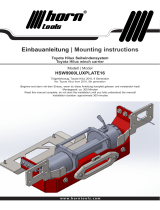
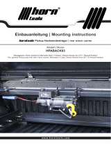
Einbauanleitung | Mounting instructions
für Seilwinden Montagesystem
for winch mounting system
Modell | Model
HSW9900ISDMDY_PA
Trägerfahrzeug: ISUZU DMAX Bj. 2021 –
fits: ISUZU DMAX manufacturing year 2021 and following

Datum / date: 2 | 2817.05.2022 Seite / page:
Technische Änderungen vorbehalten / technical changes reserved
Allgemeine Hinweise | universal notes
► Fragen / questions
Solltest du noch Fragen zur Montage oder zum Gebrauch deines Produktes haben, kontaktiere uns gerne.
If you have further questions regarding the mounting or the useage of your horntools product feel free to contact
us.
► Ersatzteile / spare parts
erhaltest du von deinem horntools Fachhändler /
contact your local horntools dealer
► Haftung / liability
Bei Nichtbeachtung der in dieser Anleitung angegebenen Hinweise und Informationen, bei nicht
bestimmungsgemäßem Gebrauch oder bei Einsatz außerhalb des vorgesehenen Verwendungszwecks, lehnt der
Hersteller die Gewährleistung für Schäden am Produkt ab.
Die Haftung für Folgeschäden an Elementen aller Art oder Personen ist ausgeschlossen. In case of non-
observance of this manual and its information or non-specied usage of the product, the manufacturer does not
give any kind of warranty of damage on the product.
The liability is excluded for consequential damages in any
kind for material or persons.
► Rechtliche hinweise / legal notice
Grak- und Textteile dieser Anleitung wurden mit Sorgfalt hergestellt. Für eventuell vorhandene Fehler und deren
Auswirkung kann keine Haftung übernommen werden! Technische Änderungen am Produkt sowie in dieser
Anleitung sind vorbehalten!
horntools excludes the liability for mistakes in the images or text phrases in this manual. Technical changes
reserved!
► Kennzeichnung von Gefahren / symbols for dangerous operation
Achtung! Dieses Symbol weist auf wichtige Arbeitsschritte hin, bei Nichtbeachtung kann es zu
Beschädigung am Produkt oder Verletzungen kommen!
Whenever this symbol is placed at an installation step special care must be taken. If you don’t
follow the instructions you could either damage the product or injure yourself!
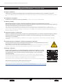
► Wichtig / important
Scanne diesen QR Code, um die Einbauanleitung auf deinem Smartphone zu önen.
Prüfe, ob die Versionsnummer (unten) dieselbe ist! Es kann sein, dass online bereits
eine aktualisierte Version (höherer Code) zur Verfügung steht – dann muss diese
verwendet werden.
Scan this QR Code to open this instruction on your mobile phone! Make sure that
the online and the printed instruction are the same version (code below)! It could be
possible that there is already an updated online version available.
If the version code of the online manual is higher than this one use the online manual!
Wenn du den QR Code nicht önen kannst hier der Link:
If you can’t read the QR Code we stated the link here:
https://www.horntools.com/pub/more_downloads/hsw9900isdmplate_ins_man_de_en.pdf
VERSION: V1

3 | 28
Seite / page:
Datum / date: 17.05.2022
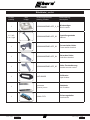
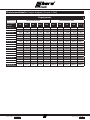
Stückliste | partlist
Anzahl
quantity
Bild
image
Zeichnungsnummer
drawing number
Beschreibung
description
1
HSW9900ISDMPLATE_X_01 Windenträger
Winch carrier
1 li / left
1 re / right
HSW9900ISDMPLATE_02 Versteifungsstrebe
stiener
1
HSW9900ISDMPLATE_03 Trennschalter Halter
Power switch bracket
1
HSW9900ISDMPLATE_04 Steuerbox Halter
controlbox bracket
1
HSW9900ISDMPLATE_05 Halter Fernbedienung
bracket remote control
1
HAF15000B Seilfenster
rope window
1
Symbolbild
symbolic picture
Kabelsatz
set of cables
1
HANL-C-FH Sicherungshalter
fuse bracket

Datum / date: 4 | 2817.05.2022 Seite / page:
Technische Änderungen vorbehalten / technical changes reserved
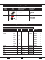
Stückliste | partlist
Anzahl
quantity
Bild
image
Zeichnungsnummer
drawing number
Beschreibung
description
2
HANL500A Sicherung
fuse
1
H0100 Trennschalter
circuit breaker
Windenträger | winch carrier
Artikel
article
Größe
size
Festigkeit
strength
Koporm
head
Oberäche
surface DIN / ISO Stk.
quant.
Schraube
bolt M10x40 8.8 Sechskant
hex
Verzinkt
galvanized DIN933 4
Scheibe
washer M10 Verzinkt
galvanized DIN125 4
Schraube
bolt M10x30 10.9 Sechskant
hex
Verzinkt
galvanized DIN933 4
Scheibe
washer M10 Verzinkt
galvanized DIN125 4
Schraube
bolt M10x30 10.9 Zylinder
cylinder
Verzinkt
galvanized DIN912 3
Scheibe
washer M10 Verzinkt
galvanized DIN125 3
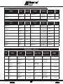
Schraube
bolt M10x80 8.8 Sechskant
hex
Verzinkt
galvanized DIN933 4
Scheibe
washer M10 Verzinkt
galvanized DIN9021 6
Mutter
nut M10 Sechskant
hex
Verzinkt
galvanized DIN985 2
Schraube
bolt M6 Zylinder
cylinder
Verzinkt
galvanized DIN914 4
Schraube
bolt M8x20 10.9 Hex Verzinkt
galvanized ISO7380 4
Scheibe
washer M8 Inbus
allen key
Verzinkt
galvanized DIN125 4
Schraubenliste | boltlist

5 | 28
Seite / page:
Datum / date: 17.05.2022
Seilfenster | rope window
Artikel
article
Größe
size
Festigkeit
strength
Koporm
head
Oberäche
surface DIN / ISO Stk.
quant.
Schraube
bolt M12x30 8.8 cylindrical Edelstahl
stainless DIN912 2
Scheibe
washer M12 Edelstahl
stainless DIN125 2
Not-Aus & Steuerbox | power switch & controlbox
Artikel
article
Größe
size
Festigkeit
strength
Koporm
head
Oberäche
surface DIN / ISO Stk.
quant.
Schraube
bolt M8x35 8.8 Zylinder
cylinder
Verzinkt
galvanized DIN912 2
Scheibe
washer M8 Verzinkt
galvanized DIN125 2
Schraube
bolt M5x16 8.8 Sechskant
hex
Verzinkt
galvanized DIN933 2
Scheibe
washer M5 Verzinkt
galvanized DIN125A 4
Mutter
nut M5 8 Sechskant
hex
Verzinkt
galvanized DIN985 2
Schraube
bolt M6x20 8.8 Linsenkopf
lens head
Verzinkt
galvanized ISO7380 1
Scheibe
washer M6 Verzinkt
galvanized DIN125 2
Mutter
nut M6 8 Sechskant
hex
Verzinkt
galvanized DIN985 2
Kabelliste | cable list
Stk.
qty.
Name
name
Farbe
color
Querschnitt
cross sect.
Öse 1 Farbe
eyelet 1 color
Öse 2 Farbe
eyelet 2 color
Länge
length
1 Bat+ Schwarz
black 35 mm2M8 M8 50 cm
1 Bat+2Schwarz
black 35 mm2M8 M10 / Rot
M10 / red 145 cm
1 Not-Aus Schwarz
black 35 mm2M10 / Rot
M10 / red M8 120 cm
1 Masse Schwarz
black 35 mm2M8 M8 220 cm
1 F2 Schwarz
black 35 mm2M8 M8 / Rot
M8 / red 120 cm
1 A+ Schwarz
black 35 mm2M8 M8 / Blau
M8 / blue 100 cm
1 F1 Schwarz
black 35 mm2M8 M8 / Gelb
M8 / yellow 80 cm

Datum / date: 6 | 2817.05.2022 Seite / page:
Technische Änderungen vorbehalten / technical changes reserved
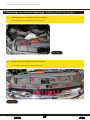
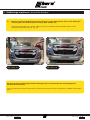
Demontage der vorderen Stoßstange | detaching of the front bumper
Abb. 1/Fig. 1
1.1 Luftansaugung vom Luftlter demontieren (Abb.1).
Disassemble the air intake from the air lter (Fig.1).
1.
Abb. 2/Fig. 2
1.2 Blende vom Schlossträger demontieren (Abb.2).
Dismantle the cover from the lock carrier (Fig.2).

7 | 28
Seite / page:
Datum / date: 17.05.2022
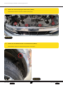
Abb. 3/Fig. 3
1.3 Oberen Kühlergrill demontieren (Abb.3, Abb.4).
Disassemble upper radiator grille (Fig.3, Fig.4).
Abb. 4/Fig. 4

Datum / date: 8 | 2817.05.2022 Seite / page:
Technische Änderungen vorbehalten / technical changes reserved
Abb. 5/Fig. 5
1.4 Nieten des unteren Kühlergrills demontieren (Abb.5).
Dismantle the rivets of the lower radiator grille (Fig.5).
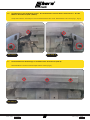
Abb. 6/Fig. 6
1.5 Nieten aus der Radhausschale L & R demontieren (Abb.6).
Disassemble rivets from wheel housing shell L & R (Fig.6).

9 | 28
Seite / page:
Datum / date: 17.05.2022
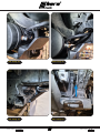
Abb. 7/Fig. 7
1.6 Die Abdeckung der Stoßstange unten L & R ausklammern und die Nieten demontieren. L & R die
Muttern demontieren (Abb.7, Abb.8).
Unclip the bottom L & R bumper cover and disassemble the rivets. Disassemble L & R nuts (Fig.7, Fig.8).
Abb. 8/Fig. 8
Abb. 9/Fig. 9
1.7 Die Schrauben der Stoßstange in der Mitte unten demontieren (Abb.9).
Disassemble the screws of the bumper bottom center (Fig.9).

Datum / date: 10 | 2817.05.2022 Seite / page:
Technische Änderungen vorbehalten / technical changes reserved
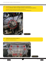
Abb. 10/Fig. 10
1.8 Die Stoßstange vorsichtig am Kotügel ausklammern und abnehmen.
Achtung: Die Stecker müssen noch gelöst werden (in Fahrtrichtung links) (Abb.10).
Carefully unclip the bumper from the fender and remove it.
Attention: The plugs must still be disconnected (on the driver side) (Fig.10).
1.9 Unterbodenschutz entfernen (Abb.11).
Remove the skid plate (Fig.11).
Abb. 11/Fig. 11

11 | 28
Seite / page:
Datum / date: 17.05.2022
Montage der Seilwinde auf die Trägerplatte | Mounting the winch on the
support plate.
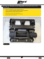
2.1 Montiere die Seilwinde auf die Trägerplatte (Abb.12).
Hinweis: Die Drehmomenttabelle ndest du auf der letzten Seite.
(M10X30Schrauben mit M10 Scheiben montieren)
Mount the winch on the support plate (Fig.12).
Note: The torque table can be found on the last page.
(M10X30 bolts with M10 washers)
2.
Abb. 12/Fig. 12

Datum / date: 12 | 2817.05.2022 Seite / page:
Technische Änderungen vorbehalten / technical changes reserved
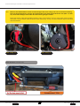
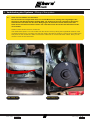
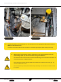
2.2 Montiere das Elektrokabel mit der Isolationskappe Rot in der Länge 120 cm an die Verschraubung
Rot vom Seilwindenmotor. Verlege des Elektrokabel unter dem Seilwindenmotor her (Abb. 13, Abb.
14). Die Isolationskappe muss über den Anschluss gezogen werden.
Mount the electric cable with the RED insulation caps, in the length of 120 cm, to the winch motor red bolt
connection. Lay the electric cable under the winch motor (Fig. 13, Fig. 14).The insulation cap must be sled
over the terminal.
Abb. 13/Fig. 13 Abb. 14/Fig. 14
Bitte beachten / Please note:

13 | 28
Seite / page:
Datum / date: 17.05.2022
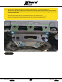
2.3 Montiere die Trägerplatte mit der vormontieren Seilwinde an das Fahrzeug (Abb.15).
Verwende bei den Grün markierten Schraubenlöchern die M10 x30 Inbusschrauben (Feingewinde).
Verwende bei den Blau markierten Schraubenlöchern die M10x40 Schrauben (Feingewinde) mit den
Unterlegscheiben M10.
Mount the carrier plate with the pre-assembled winch to the vehicle (Fig.15).
Use the M10x30 cylinder head bolts (ne thread) for the screw holes marked in green.
Use the screws M10x40 with the washers M10 for the screw holes marked in blue.
Abb. 15/Fig. 15

Datum / date: 14 | 2817.05.2022 Seite / page:
Technische Änderungen vorbehalten / technical changes reserved
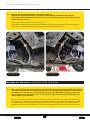
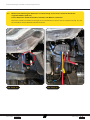
2.4 Montage der Versteifungsstreben L & R (Abb.16, Abb.17)
Montiere die Versteifungsstreben mit den Schrauben M10x80, den Muttern M10 und den
Unterlegscheiben M10. Stelle die Streben zuvor auf die benötigte Länge ein. Sicher dies mit den
kleinen Inbussschrauben.
Mounting the stiening struts L & R (Fig.16, Fig.17)
Assemble the stiening struts with the screws M10x80, the M10 nuts and the M10 washers. Adjust the
struts to the required length beforehand. Secure this with the small allen screws.
Abb. 16/Fig. 16 Abb. 17/Fig. 17
Montage der Steuerbox | Assembly of the control box
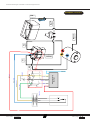
2.5 Bevor du die Steuerbox montieren kannst, müssen zuerst die Kabel an den jeweiligen Anschlüssen
der Steuerbox befestigt werden. Dafür entferne zuerst die Abdeckung der Steuerbox. Verbinde nun
die Kabel A+, F1 und Not Aus wie im Schaltplan am Ende der Montageanleitung beschrieben mit
den jeweiligen Polen. Die Kabel kannst du anhand der Längen und den farbigen Endkappen gut
unterscheiden (vgl. Kabelliste).
Before you can mount the control box, the cables must rst be attached to the respective connections of
the control box. To do this, rst remove the cover of the control box. Now connect the cables A+, F1 and
Emergency O to the respective poles as described in the circuit diagram at the end of the installation
instructions. You can easily distinguish the cables by their lengths and coloured end caps (see cable list).

15 | 28
Seite / page:
Datum / date: 17.05.2022
Abb. 18/Fig. 18 Abb. 19/Fig. 19
Verkabelung des Systems | Wiring of the system
3.1 Kabel F2 vom E-Motor zur Steuerbox
Das bei Punkt 2.2 verlegte Kabel wird nun vom E-Motor hoch, entlang des Längstträgers der
Karosserie zum Steuerboxhalter geführt (Abb. 18). Achte hier auf eine scheuerfreie Verlegung.
Verbinde das rote Kabel mit der freien Belegung an der Steuerbox. Achte darauf, dass das
Kabel keinen Kontakt zu anderen Kabeln hat. Jetzt kannst du den Deckel der Steuerbox wieder
verschließen.
Cable F2 from electric motor to control box
The cable laid at point 2.2 is now routed from the electric motor up along the longitudinal member of the
controlbox bracket (Fig. 18). Make sure that the cable is laid without chang. Connect the red cable to the
free pinout on the control box. Make sure that the cable has no contact with other cables. Now you can
close the cover of the control box.
3.

Datum / date: 16 | 2817.05.2022 Seite / page:
Technische Änderungen vorbehalten / technical changes reserved
3.2 Montiere die Halterung der Steuerbox in Fahrtrichtung vorne rechts. Verwende hierfür die
originalen Muttern (Abb. 20).
Für die Steuerbox die M5 Schrauben, Scheiben und Muttern verwenden.
Mount the control box bracket on the right front in the direction of travel. Use the original nuts (Fig. 20). For
the controlbox use the M5 bolts, washers and nuts.
Abb. 20/Fig. 20 Abb. 21/Fig. 21

17 | 28
Seite / page:
Datum / date: 17.05.2022
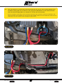
3.3 Kabel F1 von der Steuerbox zum Elektromotor
Führe das Kabel F1, welches bereits an der Steuerbox montiert ist, mit der gelben Isolationskappe
von hier nach unten, entlang des Längstträgers der Karosserie (Abb. 22) zum Elektromotor.
Schließe das Kabel F1 mit der gelben Isolationskappe an den gelben Anschluss des Elektromotors
an (Abb. 23). Achte hier auf eine scheuerfreie Verlegung.
Cable F1 from control box to electric motor
Lead the cable F1, which is already mounted on the control box, with the yellow insulation cap from here
on downwards, along the longitudinal beam of the chassis (g. 22) to the electric motor. Connect cable F1
with the yellow insulation cap to the yellow connection of the electric motor (g. 23). Make sure that the
cable is laid without chang.
Abb. 22/Fig. 22 Abb. 23/Fig. 23
3.4 Kabel A+ von der Steuerbox zum Elektromotor
Führe das Kabel A+, welches bereits an der Steuerbox montiert ist, mit der blauen Isolationskappe
von hier nach unten, entlang des Längstträgers der Karosserie (Abb. 24) zum Elektromotor.
Schließe das Kabel A+ mit der blauen Isolationskappe an den blauen Anschluss des Elektromotors
an (Abb. 25). Achte hier auf eine scheuerfreie Verlegung und xiere alle Kabel mit geeigneten
Kabelbindern.
Cable A+ from control box to electric motor
Lead the cable A+, which is already mounted on the control box, with the blue insulation cap from here
downwards, along the longitudinal beam of the body (g. 24) to the electric motor. Connect the A+ cable
with the blue insulation cap to the blue connection of the electric motor (g. 25). Make sure that the cable is
laid without chang and x all cables with suitable cable ties.

Datum / date: 18 | 2817.05.2022 Seite / page:
Technische Änderungen vorbehalten / technical changes reserved
Abb. 24/Fig. 24 Abb. 25/Fig. 25
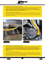
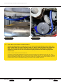
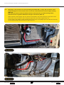
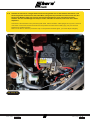
3.5 Kabel Masse vom E-Motor zur Batterie Minus
Schließe das Kabel Masse (Länge 220 cm) an die Verschraubung des Elektromotors (Abb. 26) an.
Führe es dann über den unteren Querträger (Abb. 27, Abb. 28) zwischen Kühler und Längstträger
(Abb. 29) nach oben zur Batterie (Abb. 30). Schließe das Kabel an den Minuspol der Batterie
an (Abb. 31). Achte hier auf eine scheuerfreie Verlegung und xiere das Kabel mit geeigneten
Kabelbindern.
Cable A+ from electric motor to control box
Connect the earth cable (length 220 cm) to the screw connection of the electric motor (Fig. 26). Then
lead it upwards to the battery (Fig. 30) via the lower cross member (Fig. 27, Fig. 28) between the radiator
and the longitudinal member (Fig. 29). Connect the cable to the negative terminal of the battery (Fig. 31).
Ensure that the cable is laid without chang and secure it with suitable cable ties.

19 | 28
Seite / page:
Datum / date: 17.05.2022
Abb. 26/Fig. 26 Abb. 27/Fig. 27
Abb. 28/Fig. 28 Abb. 29/Fig. 29

Datum / date: 20 | 2817.05.2022 Seite / page:
Technische Änderungen vorbehalten / technical changes reserved
Abb. 30/Fig. 30 Abb. 31/Fig. 31
3.6 Schließe das dünne schwarze Kabel von der Steuerbox an einen geeigneten Massepunkt (blankes
Metall) an der Karosserie an.
Connect the thin black cable from the control box to a suitable ground point (bare metal) on the body.
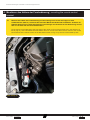
3.7 Montiere den Trennschalter samt der Halterung an der mittleren Strebe unter dem
Schlossträger (Abb. 33). Verwende hierfür die originalen Muttern.
Den Schlüssel des Trennschalters während der Montage nicht einstecken! Das kann zu
einem Kurzschluss im System führen.
Fit the emergency switch and its bracket to the middle strut under the lock carrier (Fig. 33).
Use the original nuts for this.
Do not insert the key of the power switch during assembly! This can lead to a short circuit in
the system.
Seite wird geladen ...
Seite wird geladen ...
Seite wird geladen ...
Seite wird geladen ...
Seite wird geladen ...
Seite wird geladen ...
Seite wird geladen ...
Seite wird geladen ...
-
 1
1
-
 2
2
-
 3
3
-
 4
4
-
 5
5
-
 6
6
-
 7
7
-
 8
8
-
 9
9
-
 10
10
-
 11
11
-
 12
12
-
 13
13
-
 14
14
-
 15
15
-
 16
16
-
 17
17
-
 18
18
-
 19
19
-
 20
20
-
 21
21
-
 22
22
-
 23
23
-
 24
24
-
 25
25
-
 26
26
-
 27
27
-
 28
28


horntools HSW9900ISDMDY_PA Bedienungsanleitung
- Typ
- Bedienungsanleitung
in anderen Sprachen
Verwandte Artikel
-
 horntools HSW9940JIMII_X Bedienungsanleitung
-
 horntools HSW9900TOHI16 Bedienungsanleitung
-
 horntools HSW9940JIMIIPLATE Bedienungsanleitung
-
 horntools HPABACK039500_X Bedienungsanleitung
-
 horntools HMAXRR01NG_X Bedienungsanleitung
-
 horntools HSW9900IVDAPLATE Bedienungsanleitung
-
 horntools HPABACK03_X Bedienungsanleitung
-
 horntools HUFJIMII13 Bedienungsanleitung
-
 horntools HRANRR01NG_X Bedienungsanleitung
-
 horntools HSW9900JIM_X Bedienungsanleitung


