Rademacher Comfort 2360 20 80 Benutzerhandbuch
- Typ
- Benutzerhandbuch

VBD-285-24-5 (06.21)
EN Installation Instructions for the RolloTube Automation Set ...........................5
Comfort 2360 20 80
S-line DuoFern Medium
20 Nm / 16 U-min
ja
1
1
-
1
1
1
1
4
1
1
bis 185 cm
Basis 2160 20 90
Basis Medium
20 Nm / 16 U-min
nein
1
1
1
1
1
1
1
4
1
1
bis 185 cm
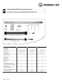
Automatisierungs-Set
Lieferumfang:
Rohrmotor (Typ):
Nenndrehmoment:
Steckbares Kabel:
Adapter + Mitnehmer:
Einbauanleitung:
Einstellwerkzeug:
Click-Antriebslager:
Altbaulager:
8-Kant-Wickelwelle (60 mm x 0,6):
Teleskopverlängerung, inkl. Walzenkapsel:
Befestigungsfedern:
Gegenlager, inkl. Kugellager:
Montagematerial (im Beipackkarton):
Einsatzbereich/Fensterbreite:
Standard 2660 20 00
M-line Medium
20 Nm / 16 U-min
ja
1
1
-
1
1
1
1
4
1
1
bis 185 cm
DE Einbauanleitung RolloTube Automatisierungs-Set ..........................................1
Automatisierungs-Set Comfort / Standard
Automatisierungs-Set Basis

2
DE
Diese Anleitung...
i
...beschreibt Ihnen in Kurzform die Montage der RolloTube Automatisie-
rungs-Sets.
Diese Anleitung ersetzt nicht die beiliegende Anleitung des
Rohrmotors.
Bitte lesen Sie diese Anleitung vollständig durch und beachten Sie alle
Sicherheitshinweise, bevor Sie mit den Arbeiten beginnen.
Bei Schäden, die durch Nichtbeachtung dieser Anleitungen und der Sicher-
heitshinweise entstehen, erlischt die Garantie. Für Folgeschäden, die daraus
resultieren, übernehmen wir keine Haftung.
Bei allen Arbeiten an elektrischen Anlagen besteht Lebensgefahr
durch Stromschlag.
◆ Der Netzanschluss des Rohrmotors und alle Arbeiten an elektrischen Anla-
gen dürfen nur durch eine zugelassene Elektrofachkraft nach den Anschluss-
plänen in der Originalanleitung des beiliegenden Rohrmotors erfolgen.
◆ Führen Sie alle Montage- und Anschlussarbeiten im spannungslosen Zu-
stand aus.
Bei Nichtbeachtung besteht Lebensgefahr!
Vorschriften bei Installation in Feuchträumen beachten.
◆ Beachten Sie besonders beim Einsatz in Feuchträumen die DIN VDE 0100,
Teil 701 und 702. Diese Vorschriften enthalten zwingende Schutz-
maßnahmen.
Montage
ACHTUNG!
Schlagen Sie nie den Motor (8) mit
Gewalt in die Wickelwelle (5.2) ein.
Das führt zu seiner Zerstörung.
ACHTUNG!
Nie im Bereich des Antriebs bohren
oder schrauben um den Rollladen
zu befestigen.
Die alte Rollladenmechanik ausbauen
◆ Den Rollladenkasten öffnen.
◆ Den Rollladen vollständig schließen und den Rollladenpanzer von der
Wickelwelle lösen.
◆ Danach den vorhandenen Gurtwickler und das Wickelband demontieren,
und die Gurteinlassöffnung im Rollladenkasten verschließen.
VORSICHT!
Es besteht Verletzungsgefahr durch die vorgespannte Feder im alten
Gurtwickler.
Halten Sie die Federdose beim Lösen des Gurtbandes gut fest und lassen Sie
sie langsam zurückdrehen, bis die Federdose vollständig entspannt ist.
1.
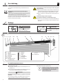
◆ Die Wickelwelle und alle Lager demontieren.
(14)
1
(1) (2) (4) (6)
(5.2) (7) (8) (9) (11) (12)(3) (10)
(5.1)
(1) Gegenlager
(2) Kugellager
(3) Achsstift der Walzenkapsel
(4) Walzenkapsel
(5.1) Teleskopwelle
(5.2) Wickelwelle
(6) Befestigungsfedern bzw.
starre Wellenverbinder
(7) Mitnehmer
(8) Rohrmotor
(9) Adapter
(10) Setztaste bzw.
2 Einstellschrauben
(11) Antriebskopf
(12) Click-Antriebslager
(13) * Motorkabel mit/ohne Stecker,
siehe Seite 1
(14) Rollladenpanzer
(13) *
i Markieren Sie jeweils die Position der Lagermitte
der alten Lager, damit Sie später die neuen Lager
und die Wickelwelle waagerecht an gleicher
Position einbauen können.

3
Montage
2
DE
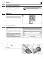
Montage der Lager
3.
◆Montieren Sie die neuen Lager entsprechend den vorher gemachten
Positionsmarkierungen der alten Lager. Stellen Sie dabei sicher, dass
die Wickelwelle waagerecht eingebaut werden kann, und dass die erste
Lamelle des aufgewickelten Rollladenpanzers senkrecht in die Führungs-
schiene des Fensters läuft.
◆Befestigen Sie die Lager je nach Lagertyp und bauseitigen Gegebenhei-
ten.
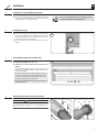
L = A - (B + C)
3
Länge der Wickelwelle ermitteln
4.
◆Länge der Wickelwelle: L = A - (B + C)
◆Montage bis 185 cm Fensterbreite mit Hilfe der Teleskopwelle
(5.1)
Zur Montage bei Fensterbreiten ab 105 cm bis 185 cm können Sie die Teles-
kopwelle (5.1) bis auf die benötigte Länge aus der 8-kant Wickelwelle (5.2)
herausziehen.
Ist das Fenster schmaler als die Wickelwelle (5.2) müssen Sie diese auf
das benötigte Maß kürzen. Sägen Sie beide Wickelwellen mit einer
Eisensäge rechtwinklig auf Maß. Entgraten Sie die Kanten der Wickel-
wellen innen und außen mit einer Feile.
Halten Sie immer eine Mindesteinstecktiefe von 200 mm für
die Teleskopwelle (5.1) ein.
(7)
(8)
(5.2) (9)
(5.2)
(11)
(15)
4(10)
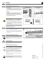
Den Rohrmotor in die Wickelwelle schieben
5.
ACHTUNG!
Achten Sie darauf, dass der Adapter (9) während der Montage nicht vom
Adapterring (15) am Antriebskopf (11) abrutscht, es kann sonst zu Fehl-
funktionen kommen.
Einsatzbedingungen und Montagevorbereitungen2.
◆Für den elektrischen Anschluss des Rohrmotors muss am Einsatzort
ständig ein 230 V / 50 Hz Netzanschluss (L/N/PE) mit bauseitiger
Freischaltvorrichtung (Sicherung) vorhanden sein.
Bitte beachten Sie die Installations- und Anschlusspläne in der
beiliegenden Bedienungsanleitung des Rohrmotors.

4
Technische Änderungen, Druckfehler und Irrtümer vorbehalten. Abbildungen unverbindlich.
Montage D
(5.1) (6)
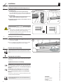
6
Montage des Rollladenpanzers
7.
(5.2)
◆ Schieben Sie die Befestigungsfedern bzw. die starren Wellenverbinder (6)
auf die oberste Lamelle des Rollladenpanzers (14).
◆ Setzen Sie alle 40 cm eine Befestigungsfeder bzw. einen starren Wellen-
verbinder (6) in die rechteckigen Löcher der Wickelwelle (5.2) und der
Teleskopwelle (5.1).
(14)
Elektrische Inbetriebnahme/Einstellungen
8.
Beachten Sie dazu die Angaben in der beiliegenden Bedienungsanleitung
des Rohrmotors.
Einbau des Rohrmotors in die Lager (12) / (1)
6.
(10) (11) (12)
(5.1)
(1)
(2)
◆Click-Antriebslager
Den Antriebskopf (11) in das Click-Antriebslager (12) drücken.
Die Setztaste (10) muss gut zugänglich sein. Das gilt ebenfalls für die Ein-
stellschrauben zur Einstellung der Endpunkte bei mechanischen Rohr-
motoren.
◆Gegenlager
Auf der anderen Seite die Teleskopwelle (5.1) mit aufgestecktem
Kugellager (2) von oben in das Gegenlager (1) drücken.
◆ Abschließend beide Wickelwellen (5.1 und 5.2) mit den beiliegen-
den Flachkopfschrauben (16) fixieren.
5
STOP
Click-Antriebslager Gegenlager
(16)
Garantiebedingungen
Informationen zu Garantiebedingungen unserer Produkte finden Sie auf
unserer Homepage.
(16)
(5.2)
RADEMACHER
Geräte-Elektronik GmbH
Buschkamp 7
46414 Rhede (Deutschland)
Vereinfachte EU-Konformitätserklärung
Hiermit erklärt die RADEMACHER Geräte-Elektronik GmbH, dass die Funk-Rohr-
motoren der Serie RolloTube S-line DuoFern den Richtlinien 2006/42/EG (Ma-
schinenrichtlinie) und 2014/53/EU (Funkanlagenrichtlinie) entsprechen.
Beachten Sie dazu auch die Angaben in der beiliegenden Bedienungsanlei-
tung des jeweiligen Rohrmotors.
Hiermit erklärt die RADEMACHER Geräte-Elektronik GmbH, dass die
Rohrmotoren der Serien RolloTube M-line / RolloTube Basis den Richtlinien
2006/42/EG (Maschinenrichtlinie) und 2014/30/EU (EMV-Richtlinie)
entsprechen.
Der vollständige Text der EU-Konformitätserklärung liegt dem Produkt bei
und ist beim Hersteller hinterlegt.
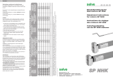
WARNUNG!WARNUNG!
Kurzschlussgefahr durch Wasser bei falscher Kabelführung.
◆Verlegen Sie das Motorkabel (13) nie direkt senkrecht nach oben, sonst
kann evtl. Wasser über das Kabel in den Motor laufen und diesen zerstören.
◆Verlegen Sie das Kabel in einer Schlaufe. Die Schlaufe bewirkt, dass am
Kabel ablaufendes Wasser am tiefsten Punkt der Schlaufe gesammelt
wird und dort abtropft.
i
DE

VBD-285-24-5 (06.21)
Comfort 2360 20 80
S-line DuoFern Medium
20 Nm / 16 rpm
yes
1
1
-
1
1
1
1
4
1
1
Up to 185 cm
Basic 2160 20 90
Basic Medium
20 Nm / 16 rpm
no
1
1
1
1
1
1
1
4
1
1
Up to 185 cm
Automation Set
Included in delivery:
Tubular motor (type):
Nominal torque:
Plug-in cable:
Adapter + catch:
Installation instructions:
Adjustment tool:
Click drive bearing:
Clamp bearing:
Octagonal winding shaft (60 mm x 0.6):
Telescopic extension, incl. roller capsule:
Ties:
Counter bearing, incl. ball bearing:
Installation material (in the accessory pack):
Application/window width:
Standard 2660 20 00
M-line Medium
20 Nm / 16 rpm
yes
1
1
-
1
1
1
1
4
1
1
Up to 185 cm
EN Installation Instructions for the RolloTube Automation Set ......................5
Comfort / Standard Automation Set
Basic Automation Set
DE Einbauanleitung RolloTube Automatisierungs-Set ..........................................1

6
EN
These instructions...
i
...give you a brief description of the installation of the RolloTube Automation
Set.
These instructions do not replace the enclosed manual for the
tubular motor.
Before you begin, please read these instructions through completely and
follow all the safety instructions.
Damage resulting from non-compliance with these instructions and the safety
instructions will void the warranty. We assume no liability for any consequential
damage.
There is a risk of fatal injury from electric shock when working on all
electrical systems.
◆ The electrical connection for the tubular motor and all work on the electrical
systems may only be undertaken by an authorised electrician in accordance
with the connection diagrams in the original manual for the enclosed tubular
motor.
◆ Carry out all installation and connection work only when the product is
disconnected from the mains power.
There is a risk of fatal injury in the event of failure to observe these
instructions!
Observe the regulations for installing products in damp rooms.
◆ Observe DIN VDE 0100, parts 701 and 702 in particular when installing the
product in damp rooms. These regulations contain mandatory protective
measures.
Installation
ATTENTION!
Never knock the motor (8) into the
winding shaft (5.2) with force.
Doing so will cause serious damage.
ATTENTION!
Never drill in the area of the drive or
insert screws in order to secure the
roller shutter.
Removing the old roller shutter mechanism
◆ Open the roller shutter box.
◆ Close the roller shutter completely and release the roller shutter casing
from the winding shaft.
◆ Then remove the existing belt winder and winding belt and close the belt
inlet opening in the roller shutter box.
CAUTION!
There is a risk of injury from the pre-tensioned spring in the old belt
winder.
Hold the spring unit firmly when loosening the belt and allow it to recoil
slowly until the spring unit has completely unwound.
1.
◆ Remove the winding shaft and all bearings.
(14)
1
(1) (2) (4) (6)
(5.2) (7) (8) (9) (11) (12)(3) (10)
(5.1)
(1) Counter bearing
(2) Ball bearing
(3) Axle pin on the roller capsule
(4) Roller capsule
(5.1) Telescopic shaft
(5.2) Winding shaft
(6) Ties or rigid shaft connectors
(7) Catch
(8) Tubular motor
(9) Adapter
(10) Set button or 2 adjustment
screws
(11) Drive head
(12) Click drive bearing
(13) * Motor cable with/without
connector, see page 1
(14) Roller shutter casing
(13) *
i Mark the position of the centre of the old
bearings so that you can install the new bearings
and the winding shaft horizontally in the same
position.

7
Installation
2
EN
Installing the bearings
3.
◆ Install the new bearings in accordance with the previous position marks
of the old bearings. Make sure that the winding shaft can be installed
horizontally and that the first slat of the wound roller shutter casing is
perpendicular to the guide rail of the window.
◆ Fasten the bearings in accordance with the bearing type and on-site
conditions.
L = A - (B + C)
3
Determining the length of the winding shaft
4.
◆ Length of the winding shaft: L = A - (B + C)
◆ Installation up to a window width of 185 cm using the telescopic
shaft (5.1)
For installing window widths ranging from 105 cm to 185 cm, you can
pull the telescopic shaft (5.1) out of the octagonal winding shaft up to
the required length.(5.2).
If the window is narrower than the winding shaft (5.2), you will need
to shorten it to the required size. Cut both winding shafts to size with
a hacksaw at a right-angle. Remove the burrs from the edges of the
winding shafts internally and externally with a file.
Always observe a minimum insertion depth of 200 mm for the
telescopic shaft (5.1).
(7)
(8)
(5.2) (9)
(5.2)
(11)
(15)
4(10)
Sliding the tubular motor into the winding shaft
5.
ATTENTION!
Ensure that the adapter (9) does not slip off the adapter ring (15) on the
drive head (11) during the installation process, otherwise malfunctions may
occur.
Conditions of use and installation preparations2.
◆ A continuous 230 V /50 Hz mains connection (L/N/PE) must be available
at the site of operation for the electrical connection of the tubular motor
in combination with on-site switchgear (fusing).
Please observe the installation and connection diagrams in the
enclosed operating manual for the tubular motor.

8
Subject to technical modifications, misprints and errors. Illustrations not binding.
Installation D
(5.1) (6)
6
Mounting the roller shutter casing
7.
(5.2)
◆ Slide the ties or the rigid shaft connectors (6)onto the upper-most slat of
the roller shutter casing (14).
◆ Place a tie or rigid shaft connector (6) every 40 cm into the rectangular
holes of the winding shaft (5.2) and the telescopic shaft (5.1).
(14)
Electrical commissioning/settings
8.
Follow the information in the enclosed operating manual for the tubular
motor.
Installing the tubular motor in the bearings (12) / (1)
6.
(10) (11) (12)
(5.1)
(1)
(2)
◆ Click drive bearing
Press the drive head (11) into the click drive bearing (12).
The set button (10) must be easily accessible. This also applies to the
adjustment screws for setting the end points on mechanical tubular motors.
◆ Counter bearing
Press the counter bearing (1) onto the other side of the telescopic
shaft (5.1) with the fitted ball bearing (2) from above.
◆ Finally, fix both winding shafts (5.1 and 5.2) with the enclosed
flat-head screws (16).
5
STOP
Click drive bearing Counter bearing
(16)
Warranty terms and conditions
Information about the warranty conditions of our products can be found on
our homepage.
(16)
(5.2)
RADEMACHER
Geräte-Elektronik GmbH
Buschkamp 7
46414 Rhede (Germany)
Simplified EU declaration of conformity
RADEMACHER Geräte-Elektronik GmbH hereby declares that the radio tubular
motors in the RolloTube S-line DuoFern series comply with the Directives
2006/42/EC (Machinery Directive) and 2014/53/EU (Radio Equipment
Directive).
Please observe the information in the enclosed operating manual for the
respective tubular motor.
RADEMACHER Geräte-Elektronik GmbH hereby declares that the tubular
motors in the RolloTube M-line / RolloTube Basic series comply with the
Directives 2006/42/EC (Machinery Directive) and 2014/30/EU (EMC
Directive).
The full text of the EU declaration of conformity is included with the product
and is kept on file by the manufacturer.
WARNING!WARNING!
Risk of short-circuit resulting from water in the event of improper
cabling.
◆Never lay the motor cable (13) vertically upwards otherwise water may
collect on the cable and run into the motor, leading to damage.
◆Lay the cable in a loop. The loop will cause any water on the cable to collect
at the lowest point, from where it can drain off.
i
EN
-
 1
1
-
 2
2
-
 3
3
-
 4
4
-
 5
5
-
 6
6
-
 7
7
-
 8
8


Rademacher Comfort 2360 20 80 Benutzerhandbuch
- Typ
- Benutzerhandbuch
in anderen Sprachen
Verwandte Artikel
Andere Dokumente
-
CAME BELLINI Installationsanleitung
-
Genius ROLL UP 35 Bedienungsanleitung
-
-
-
-
-
Ametek Dunkermotoren D339 Bedienungsanleitung
-
 Selve SP-NHK, ≥ 30 Nm Bedienungsanleitung
-
Marantec Dynamic 6xx Bedienungsanleitung
