
ROLL-UP 35

ITALIANO
AVVERTENZE PER L’INSTALLATORE
OBBLIGHI GENERALI PER LA SICUREZZA
ATTENZIONE! È importante per la sicurezza delle persone seguire at-
tentamente tutta l’istruzione. Una errata installazione o un errato
uso del prodotto può portare a gravi danni alle persone.
Leggere attentamente le istruzioni prima di iniziare l’installazione del
prodotto.
I materiali dell’imballaggio (plastica, polistirolo, ecc.) non devono essere
lasciati alla portata dei bambini in quanto potenziali fonti di pericolo.
Conservare le istruzioni per riferimenti futuri.
Questo prodotto è stato progettato e costruito esclusivamente per l’utilizzo
indicato in questa documentazione. Qualsiasi altro utilizzo non espressa-
mente indicato potrebbe pregiudicare l’integrità del prodotto e/o rap-
presentare fonte di pericolo.
GENIUS declina qualsiasi responsabilità derivata dall’uso improprio o di-
verso da quello per cui l’automatismo è destinato.
Non installare l’apparecchio in atmosfera esplosiva: la presenza di gas o
fumi infiammabili costituisce un grave pericolo per la sicurezza.
GENIUS non è responsabile dell’inosservanza della Buona Tecnica nella
costruzione delle chiusure da motorizzare, nonché delle deformazioni che
dovessero intervenire nell’utilizzo.
Prima di effettuare qualsiasi intervento sull’impianto, togliere l’alimentazio-
ne elettrica e scollegare le batterie.
Prevedere sulla rete di alimentazione dell’automazione un interruttore
onnipolare con distanza d’apertura dei contatti uguale o superiore a 3
mm. È consigliabile l’uso di un magnetotermico da 6A con interruzione
onnipolare.
Verificare che a monte dell’impianto vi sia un interruttore differenziale con
soglia da 0,03 A.
GENIUS declina ogni responsabilità ai fini della sicurezza e del buon fun-
zionamento dell’automazione, in caso vengano utilizzati componenti
dell’impianto non di produzione GENIUS.
Per la manutenzione utilizzare esclusivamente parti originali GENIUS.
Non eseguire alcuna modifica sui componenti facenti parte del sistema
d’automazione.
L’installatore deve fornire tutte le informazioni relative al funzionamento
manuale del sistema in caso di emergenza e consegnare all’Utente utiliz-
zatore dell’impianto il libretto d’avvertenze allegato al prodotto.
Non permettere ai bambini o persone di sostare nelle vicinanze del pro-
dotto durante il funzionamento.
Tenere fuori dalla portata dei bambini radiocomandi o qualsiasi altro
datore di impulso, per evitare che l’automazione possa essere azionata
involontariamente.
L’applicazione non può essere utilizzata da bambini, da persone con ridot-
te capacità fisiche, mentali, sensoriali o da persone prive di esperienza o
del necessario addestramento.
L’utente utilizzatore deve astenersi da qualsiasi tentativo di riparazione o
d’intervento e deve rivolgersi solo ed esclusivamente a personale qualifi-
cato GENIUS o centri d’assistenza GENIUS.
L’altezza di installazione minima dell’automazione è 2.5m.
Non collegare assolutamente più motori allo stesso saliscendi.
Non collegare due saliscendi allo stesso motore.
La movimentazione dell’apparecchio deve avvenire sempre a vista.
Tutto quello che non è previsto espressamente in queste istruzioni non
è permesso.
ENGLISH
IMPORTANT NOTICE FOR THE INSTALLER
GENERAL SAFETY REGULATIONS
ATTENTION! To ensure the safety of people, it is important that you
read all the following instructions. Incorrect installation or incor-
rect use of the product could cause serious harm to people.
Carefully read the instructions before beginning to install the product.
Do not leave packing materials (plastic, polystyrene, etc.) within reach
of children as such materials are potential sources of danger.
Store these instructions for future reference.
This product was designed and built strictly for the use indicated in this
documentation. Any other use, not expressly indicated here, could com-
promise the good condition/operation of the product and/or be a source
of danger.
GENIUS declines all liability caused by improper use or use other than that
for which the automated system was intended.
Do not install the equipment in an explosive atmosphere: the presence of
inflammable gas or fumes is a serious danger to safety.
GENIUS is not responsible for failure to observe Good Technique in the con-
struction of the closing elements to be motorised, or for any deformation
that may occur during use.
Before attempting any job on the system, cut out electrical power and
disconnect the batteries.
The mains power supply of the automated system must be fitted with an
all-pole switch with contact opening distance of 3mm or greater. Use of a
6A thermal breaker with all-pole circuit break is recommended.
Make sure that a differential switch with threshold of 0.03 A is fitted up-
stream of the system.
GENIUS declines all liability as concerns safety and efficient operation of
the automated system, if system components not produced by GENIUS
are used.
For maintenance, strictly use original parts by GENIUS.
Do not in any way modify the components of the automated system.
1.
2.
3.
4.
5.
6.
7.
8.
9.
10.
11.
12.
13.
14.
15.
16.
17.
18.
19.
20.
21.
22.
23.
1.
2.
3.
4.
5.
6.
7.
8.
9.
10.
11.
12.
13.
The installer shall supply all information concerning manual operation of
the system in case of an emergency, and shall hand over to the user the
warnings handbook supplied with the product.
Do not allow children or adults to stay near the product while it is ope-
rating.
Keep remote controls or other pulse generators away from children, to
prevent the automated system from being activated involuntarily.
The application cannot be used by children, by people with reduced
physical, mental, sensorial capacity, or by people without experience or
the necessary training.
The User must not in any way attempt to repair or to take direct action
and must solely contact qualified GENIUS personnel or GENIUS service
centres.
The minimum installation height of the automated system is 2.5 m.
Do not, on any account, connect several motors to the same up-and-
down device.
Do not connect two up-and-down devices to the same motor.
The equipment must always be visible when moving.
Anything not expressly specified in these instructions is not permitted.
FRANÇAIS
CONSIGNES POUR L’INSTALLATEUR
RÈGLES DE SÉCURITÉ
ATTENTION! Il est important, pour la sécurité des personnes, de suivre
à la lettre toutes les instructions. Une installation erronée ou un
usage erroné du produit peut entraîner de graves conséquences
pour les personnes.
Lire attentivement les instructions avant d’installer le produit.
Les matériaux d’emballage (matière plastique, polystyrène, etc.) ne doi-
vent pas être laissés à la portée des enfants car ils constituent des sources
potentielles de danger.
Conserver les instructions pour les références futures.
Ce produit a été conçu et construit exclusivement pour l’usage indiqué
dans cette documentation. Toute autre utilisation non expressément indi-
quée pourrait compromettre l’intégrité du produit et/ou représenter une
source de danger.
GENIUS décline toute responsabilité qui dériverait d’usage impropre ou
différent de celui auquel l’automatisme est destiné.
Ne pas installer l’appareil dans une atmosphère explosive: la présence
de gaz ou de fumées inflammables constitue un grave danger pour la
sécurité.
GENIUS n’est pas responsable du non-respect de la Bonne Technique
dans la construction des fermetures à motoriser, ni des déformations qui
pourraient intervenir lors de l’utilisation.
Couper l’alimentation électrique et déconnecter la batterie avant toute
intervention sur l’installation.
Prévoir, sur le secteur d’alimentation de l’automatisme, un interrupteur om-
nipolaire avec une distance d’ouverture des contacts égale ou supérieure
à 3 mm. On recommande d’utiliser un magnétothermique de 6A avec
interruption omnipolaire.
Vérifier qu’il y ait, en amont de l’installation, un interrupteur différentiel
avec un seuil de 0,03 A.
GENIUS décline toute responsabilité quant à la sécurité et au bon fonc-
tionnement de l’automatisme si les composants utilisés dans l’installation
n’appartiennent pas à la production GENIUS.
Utiliser exclusivement, pour l’entretien, des pièces GENIUS originales.
Ne jamais modifier les composants faisant partie du système d’automa-
tisme.
L’installateur doit fournir toutes les informations relatives au fonctionnement
manuel du système en cas d’urgence et remettre à l’Usager qui utilise
l’installation les “Instructions pour l’Usager” fournies avec le produit.
Interdire aux enfants ou aux tiers de stationner près du produit durant le
fonctionnement.
Eloigner de la portée des enfants les radiocommandes ou tout autre
générateur d’impulsions, pour éviter tout actionnement involontaire de
l’automatisme.
Ne pas permettre aux enfants, aux personennes ayant des capacités phy-
siques, mentales et sensorielles limitées ou dépourvues de l’expérience ou
de la formation nécessaires d’utiliser l’application en question.
L’utilisateur doit s’abstenir de toute tentative de réparation ou d’interven-
tion et doit s’adresser uniquement et exclusivement au personnel qualifié
GENIUS ou aux centres d’assistance GENIUS.
La hauteur minimum d’installation de l’automatisme est de 2,5m.
Ne jamais connecter plusieurs moteurs au même commande de mou-
vement.
Ne pas connecter deux commandes de mouvements au même mo-
teur.
Toujours actionner l’appareil à vue.
Tout ce qui n’est pas prévu expressément dans ces instructions est inter-
dit.
ESPAÑOL
ADVERTENCIAS PARA EL INSTALADOR
REGLAS GENERALES PARA LA SEGURIDAD
ATENCION! Es sumamente importante para la seguridad de las
personas seguir atentamente las presentes instrucciones. Una
instalación incorrecta o un uso impropio del producto puede
14.
15.
16.
17.
18.
19.
20.
21.
22.
23.
1.
2.
3.
4.
5.
6.
7.
8.
9.
10.
11.
12.
13.
14.
15.
16.
17.
18.
19.
20.
21.
22.
23.

1
ITALIANO
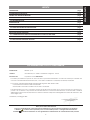
DICHIARAZIONE CE DI CONFORMITÁ
Fabbricante: GENIUS S.p.A.
Indirizzo: Via Padre Elzi, 32 - 24050 - Grassobbio- Bergamo - ITALIA
Dichiara che: L’operatore mod. ROLL-UP 35
è costruito per essere incorporato in una macchina o per essere assemblato con altri macchinari per costituire una
macchina ai sensi della Direttiva 98/37/CE, e successive modifiche 91/368/CEE, 93/44/CEE, 93/68/CEE
è conforme ai requisiti essenziali di sicurezza delle seguenti altre direttive CEE:
73/23/CEE e successiva modifica 93/68/CEE.
89/336/CEE e successiva modifica 92/31/CEE e 93/68/CEE
e inoltre dichiara che non è consentito mettere in servizio il macchinario fino a che la macchina in cui sarà incor-
porato o di cui diverrà componente sia stata identificata e ne sia stata dichiarata la conformità alle condizioni
della Direttiva 98/37/CE, 89/392/CEE e successive modifiche trasposta nella legislazione nazionale dal DPR n° 459
del 24 luglio 1996.
Grassobbio, 20 Maggio 2009
L’Amministratore Delegato
D. Gianantoni
•
•
•
•
•
Note per la lettura dell’istruzione
Leggere completamente questo manuale di installazione prima di iniziare l’installazione del prodotto.
Il simbolo evidenzia note importanti per la sicurezza delle persone e l’integrità dell’automazione.
Il simbolo richiama l’attenzione su note riguardanti le caratteristiche od il funzionamento del prodotto.
INDICE
1 DESCRIZIONE pag.2
2 CARATTERISTICHE TECNICHE pag.2
3 GUIDA ALLA SCELTA DEL MOTORE pag.2
3.1 PER AVVOLGIBILI pag.2
3.2 PER TENDE DA SOLE pag.2
4 INSTALLAZIONE pag.2
4.1 ASSEMBLAGGIO DEL MOTORE TUBOLARE pag.3
4.2 INSTALLAZIONE DEL MOTORE TUBOLARE pag.3
4.3 COLLEGAMENTI ELETTRICI pag.3
5 REGOLAZIONE DEI FINECORSA pag.4
5.1 CORRELAZIONE TRA SENSO DI ROTAZIONE RULLO E FRECCE FINECORSA pag.4
5.2 REGOLAZIONE FINECORSA IN DISCESA pag.4
5.3 REGOLAZIONE FINECORSA IN SALITA pag.4

2
ITALIANO
MOTORI TUBOLARI ROLL-UP 35
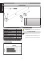
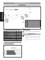
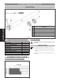
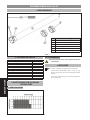
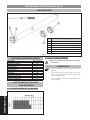
1 DESCRIZIONE
Pos. Descrizione
a
Motore tubolare
b
Esempio di adattatore ruota. (Accessorio)
c
Esempio di adattatore corona. (Accessorio)
d
Ghiera finecorsa
e
Attrezzo di regolazione finecorsa
f
Viti di regolazione finecorsa.
Fig. 1
2 CARATTERISTICHE TECNICHE
Modello Roll-up 35/18
Coppia (Nm) 10
Frequenza di utilizzo 20%
Tempo max. utilizzo (min) 4
Velocità (rpm) 14
Tensione (Vac) 230
Frequenza (Hz) 50
Potenza (W) 109
Corrente (A) 0.49
N° Rotazioni max. albero motore 37
Diametro motore (mm) 35
Lunghezza con adattatore (mm) 510
Grado di protezione IP 44
3 GUIDA ALLA SCELTA DEL MOTORE
3.1 PER AVVOLGIBILI
3.2 PER TENDE DA SOLE
Questo tipo di motore non può essere applicato a
tende da sole.
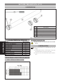
4 INSTALLAZIONE
Prima di procedere all’installazione occorre sce-
gliere:
1) L’adattatore ruota e corona (Fig. 1 rif. b - c)
più idonei al tipo di rullo da movimentare.
2) Il supporto motore più adatto all’applicazio-
ne.

3
ITALIANO
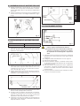
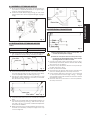
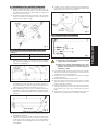
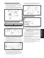
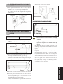
4.1 ASSEMBLAGGIO DEL MOTORE TUBOLARE
Infilare l’adattatore corona (Fig.2 rif. a ) nel motore
tubolare, fino a che questo non sia inserito completa-
mente sulla guida (Fig. 2 rif. b) presente nella ghiera
finecorsa.
Inserire l’adattatore ruota (Fig.2 rif c) nell’albero del
motore e bloccarlo con il seeger in dotazione. (Fig.2
rif. d).
Fig. 2
4.2 INSTALLAZIONE DEL MOTORE TUBOLARE
Tabella 1
MODELLO ROLL-UP 35 MISURA A (mm)
18 475
Praticare un foro con una punta Ø 3 mm sul rullo
(Fig. 3 rif. b) alla distanza A (Fig. 3 rif. a), facendo
riferimento alla tabella 1.
Fig. 3
Inserire il motore tubolare assemblato all’interno del
rullo dalla parte opposta alla calotta, fino a che
l’adattatore corona non sia completamente all’in-
terno del rullo (Fig. 4 rif. a).
Fissare l’adattatore ruota al rullo tramite una vite au-
tofilettante 4x10 inserita nel foro precedentemente
realizzato, come in figura 4 rif. b.
Fig. 4
Montare il supporto motore precedentemente scelto
dal lato della predisposizione elettrica.
Inserire il rullo motorizzato, esercitando una legge-
ra pressione nel supporto motore (Fig. 5 rif. a), e sul
supporto calotta (Fig. 5 rif. b), in modo che le viti di
regolazione di finecorsa siano accessibili.
Verificare che il rullo motorizzato sia perfettamente
orizzontale, eventualmente modificare l’altezza dei
supporti calotta o motore.
1.
2.
1.
2.
3.
4.
5.
6.
Fig. 5
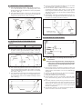
4.3 COLLEGAMENTI ELETTRICI
Fig. 6
1) Prima di effettuare qualsiasi intervento sull’im-
pianto, togliere l’alimentazione elettrica.
2) Prevedere sulla rete di alimentazione dell’auto-
mazione un interruttore onnipolare con distan-
za d’apertura dei contatti uguale o superiore a
3mm.
Collegare i fili provenienti dal motore ad un saliscendi
interbloccato e senza ritenuta come nello schema
in figura 6.
Collegare il saliscendi alla linea come in figura 6.
Alimentare l’elettrorullo.
Premere il pulsante di salita, controllare che la rotazio-
ne del rullo avvenga nella direzione di avvolgimento
e fermare il motore.
Nel caso il senso di rotazione sia errato, togliere ali-
mentazione, scambiare nel saliscendi (Fig. 6 rif. a) il
filo nero con quello marrone e verificare il corretto
funzionamento.
Premere il pulsante di discesa per verificarne il funzio-
namento, e fermare il motore.
1.
2.
3.
4.
5.
6.

4
ITALIANO
5 REGOLAZIONE DEI FINECORSA
I Motori tubolari GENIUS hanno al loro interno, un sistema di finecorsa elettromeccanico che permette di interrompere
l’alimentazione del motore quando si arriva al limite di apertura, o chiusura, dell’avvolgibile.
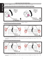
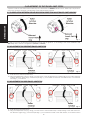
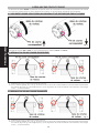
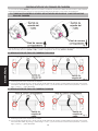
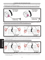
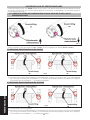
5.1 CORRELAZIONE TRA SENSO DI ROTAZIONE RULLO E FRECCE FINECORSA
Fig. 7
Per facilitare l’individuazione delle viti di regolazione finecorsa, fare riferimento alle figure 8 - 9 in base al lato montaggio
motore (DX o SX), e alla configurazione del cassonetto (interno o esterno).
5.2 REGOLAZIONE FINECORSA IN DISCESA
Fig. 8
Tenere premuto il pulsante discesa
Con l’attrezzo di regolazione (Fig. 1 rif. e) , girare la vite del finecorsa corrispondente al senso di rotazione discesa
del rullo (Fig. 8 rif. a), verso il segno più (+) per aumentare la corsa dell’avvolgibile, verso il segno meno ( - ) per
diminuirla.
5.3 REGOLAZIONE FINECORSA IN SALITA
Fig. 9
Tenere premuto il pulsante salita.
Con l’attrezzo di regolazione (Fig. 1 rif. e) , girare la vite del finecorsa corrispondente al senso di rotazione salita
del rullo (Fig. 9 rif. a), verso il segno più (+) per aumentare la corsa dell’avvolgibile, verso il segno meno ( - ) per
diminuirla.
1.
2.
1.
2.

5
ENGLISH
INDEX
1 DESCRIPTION page.6
2 TECHNICAL SPECIFICATIONS page.6
3 GUIDE FOR CHOOSING THE MOTOR page.6
3.1 FOR ROLLER SHUTTERS page.6
3.2 FOR AWNINGS page.6
4 INSTALLATION page.6
4.1 ASSEMBLY OF TUBULAR MOTOR page.7
4.2 INSTALLATION OF TUBULAR MOTOR page.7
4.3 ELECTRICAL CONNECTIONS page.7
5 ADJUSTMENT OF THE TRAVEL-LIMIT STOPS page.8
5.1 CORRELATION BETWEEN ROLLER ROTATION DIRECTION AND TRAVEL-LIMIT ARROWS page.8
5.2 ADJUSTMENT OF DESCENT TRAVEL-LIMIT STOP page.8
5.3 ADJUSTMENT OF RISE TRAVEL-LIMIT STOP page.8
CE DECLARATION OF CONFORMITY FOR MACHINES
Manufacturer: GENIUS S.p.A.
Address: Via Padre Elzi, 32 - 24050 - Grassobbio- Bergamo - ITALIA
Declares that: Operator model. ROLL-UP 35
is built to be integrated into a machine or to be assembled with other machinery to create a machine under the
provisions of Directive 98/37/EC, and subsequent amendments 91/368/EEC, 93/44/EEC, 93/68/EEC
conforms to the essential safety requirements of the other following EEC directives:
73/23/EEC and subsequent amendment 93/68/EEC.
89/336/EEC and subsequent amendment 92/31/EEC and 93/68/EEC
furthermore, the manufacturer declares that the machinery must not be put into service until the machine into which
it will be incorporated or of which it will become a part has been identified and its conformity to the conditions of
Directive 98/37/EC, 89/392/EEC and subsequent modifications assimilated in Italian National legislation under Presi-
dential Decree No. 459 of 24 July 1996 has been declared.
Grassobbio, 20 May 2009
The Managing Director
D. Gianantoni
•
•
•
•
•
Notes on reading the instruction
Read this installation manual to the full before you begin installing the product.
The symbol indicates notes that are important for the safety of persons and for the good condition of the
automated system.
The symbol draws your attention to the notes on the characteristics and operation of the product.

6
ENGLISH
TUBULAR MOTORS ROLL-UP 35
1 DESCRIPTIONDESCRIPTION
Pos. Description
a
Tubular motor
b
Example of wheel adaptor (Accessory)
c
Example of crown adaptor (Accessory)
d
Travel-limit stop ring-nut
e
Travel-limit stop adjustment tool
f
Travel-limit stop adjustment screws
Fig. 1
2 TECHNICAL SPECIFICATIONS
Model Roll-up 35/18
Torque (Nm) 10
Use frequency 20%
Max. use time (min) 4
Speed (rpm) 14
Voltage (Vac) 230
Frequency (Hz) 50
Power (W) 109
Current (A) 0.49
Motor shaft maz. rotation 37
Motor diameter (mm) 35
Length with adaptator (mm) 510
Protection index IP 44
3 GUIDE FOR CHOOSING THE MOTOR
3.1 FOR ROLLER SHUTTERS
3.2 FOR AWNINGS
This type of engine can not be applied to awnin-
gs
4 INSTALLATION
Before installing, select:
1) The wheel and crown adaptor (Fig.1 ref.b
- c) most suitable for the type of roller to be
moved.
2) The motor support most suitable for the appli-
cation.

7
ENGLISH
4.1 ASSEMBLY OF TUBULAR MOTOR
Fit the crown adaptor (Fig.2 ref.a) on the tubular mo-
tor, until it is completely inserted on the guide (Fig.2
ref.b) on the travel-limit ring-nut.
Insert the wheel adaptor (Fig.2 ref.c) on the motor
shaft and secure it with the supplied Seeger ring (Fig.2
ref.d)
Fig. 2
4.2 INSTALLATION OF TUBULAR MOTOR
Table 1
ROLL-UP 35 MODEL MEASURE A (mm)
18 475
Drill a hole with a 3mm diam. bit on the roller (Fig.3 ref.
b) at distance A (Fig.3 ref.a), referring to table 1.
Fig. 3
Insert the assembled tubular motor inside the roller
from the side opposite the cap, until the crown adap-
tor is completely inside the roller (Fig.4 ref.a).
Secure the wheel adaptor to the roller with a 4x10
self-tapping screw inserted in the hole you had dril-
led, as shown in Fig. 4 ref. b.
Fig. 4
Install the selected motor from the electric facilities
side.
Secure the motorised roller, exerting light pressure on
the motor support (Fig. 5 ref. a), and on the cap sup-
port (Fig. 5 ref. b), so that the travel-limit adjustment
screws are accessible.
Make sure that the motorised roller is perfectly hori-
zontal and, if necessary, modify the height of the cap
or motor supports.
1.
2.
1.
2.
3.
4.
5.
6.
Fig. 5
4.3 ELECTRICAL CONNECTIONS
Fig. 6
1) Before attempting any action on the system, cut
out the electrical power supply.
2) Install an omnipolar switch on the power sup-
ply line for the automated system, with contact
opening distance of 3mm or more.
Connect the wires coming from the motor to an in-
terlocked up-and-down device without reset facility
as in the lay-out of figure 6
Connect the up-and-down device to the power sup
-
ply line as shown in Fig. 6.
Power up the electro-roller
Press the rise push-button and check if the roller rota-
tes in the winding direction and stop the motor.
If the rotation direction is incorrect, cut power and
- in the up-and-down device (Fig. 6 ref.a ) - change
over the black wire with the brown wire and check if
operation is correct.
Press the descent push-button to check operation,
and stop the motor.
1.
2.
3.
4.
5.
6.

8
ENGLISH
5 ADJUSTMENT OF THE TRAVEL-LIMIT STOPS
A system of electro-mechanical travel-limit stop is housed inside the GENIUS tubular motors. These stops cut power to
the motor, when the opening or closing limit of the roller-shutter is reached.
5.1 CORRELATION BETWEEN ROLLER ROTATION DIRECTION AND TRAVEL-LIMIT ARROWS
Fig. 7
To help you find the travel-limit stop adjustment screws, refer to figures 8 - 9, according to the motor installation side
(RH or LH), and to the box configuration (internal or external).
5.2 ADJUSTMENT OF DESCENT TRAVEL-LIMIT STOP
Fig. 8
Hold down the descent push-button
Using the adjustment tool (Fig.1 ref.e), turn the screw of the travel-limit stop corresponding to the roller’s descent
rotation direction (Fig.8 ref.a), toward the plus sign (+) to increase the travel of the roller shutter, or toward the
minus sign (-) to reduce it.
5.3 ADJUSTMENT OF RISE TRAVEL-LIMIT STOP
Fig. 9
Hold down the rise push-button
Using the adjustment tool (Fig.1 ref.e), turn the screw of the travel-limit stop corresponding to the roller’s rise rota-
tion direction (Fig.9 ref.a), toward the plus sign (+) to increase the travel of the roller shutter, or toward the minus
1.
2.
1.
2.

9
FRANÇAIS
sign (-) to reduce it.
INDEX
1 DESCRIPTION page.10
2 CARACTÉRISTIQUES TECHNIQUES page.10
3 COMMENT CHOISIR LE MOTEUR page.10
3.1 POUR RIDEAUX À ENROULEMENT page.10
3.2 POUR STORES page.10
4 INSTALLATION page.10
4.1 ASSEMBLAGE DU MOTEUR TUBULAIRE page.11
4.2 INSTALLATION DU MOTEUR TUBULAIRE page.11
4.3 CONNEXIONS ÉLECTRIQUES page.11
5 RÉGLAGE DES FINS DE COURSE page.12
5.1 LIEN ENTRE LE SENS DE ROTATION DU ROULEAU ET LES FLÈCHES DES FINS DE COURSE page.12
5.2 RÉGLAGE DU FIN DE COURSE EN DESCENTE page.12
5.3 RÉGLAGE DU FIN DE COURSE EN MONTÉE page.12
DÉCLARATION CE DE CONFORMITÉ POUR MACHINES
Fabricant: GENIUS S.p.A.
Adresse: Via Padre Elzi, 32 - 24050 - Grassobbio- Bergamo - ITALIA
Déclare que: L’opérateur mod. ROLL-UP 35
est construit pour être incorporé à une machine ou pour être assemblé à d’autres machines afin de constituer une
machine conforme à la Directive 98/37/CE, et aux modifications 91/368/CEE, 93/44/CEE, 93/68/CEE successives
est conforme aux exigences essentielles de sécurité des directives CEE suivantes:
73/23/CEE et modification 93/68/CEE successive.
89/336/CEE et modifications 92/31/CEE et 93/68/CEE successives
et déclare, en outre, qu’il est interdit de mettre en service l’appareillage jusqu’à ce que la machine dans laquelle il
sera incorporé ou dont il deviendra un composant ait été identifiée et jusqu’à ce que la conformité aux conditions
de la Directive 98/37/CE, 89/392/CEE et modifications successives, transposée dans la législation nationale par le
DPR n° 459 du 24 juillet 1996, en ait été déclarée.
Grassobbio, 20 Mai 2009
L’Administrateur Délégué
D. Gianantoni
•
•
•
•
•
Remarques pour la lecture de l’instruction
Lire ce manuel d’installation dans son ensemble avant de commencer l’installation du produit.
Le symbole souligne des remarques importantes pour la sécurité des personnes et le parfait état de
l’automatisme.
Le symbole attire l’attention sur des remarques concernant les caractéristiques ou le fonctionnement du
produit.

10
FRANÇAIS
MOTEURS TUBULAIRES ROLL-UP 35
1 DESCRIPTION
Pos. Déscription
a
Moteur tubulaire
b
Exemple d’adaptateur de la roue (Accessoire)
c
Exemple d’adaptateur de la couronne
(Accessoire)
d
Bague de fin de course
e
Outil de réglage des fins de course
f
Vis de réglage des fins de course
Fig. 1
2 CARACTÉRISTIQUES TECHNIQUES
Modèle Roll-up 35/18
Couple (Nm) 10
Fréquence d’utilisation 20%
Temps maxi utilisation (min) 4
Vitesse (rpm) 14
Tension (Vac) 230
Fréquence (Hz) 50
Puissance (W) 109
Courrant (A) 0.49
Rotation maxi arbre moteur 37
Diamètre moteur (mm) 35
Longueur avec adaptateur (mm) 510
Indice de protection IP 44
3 COMMENT CHOISIR LE MOTEUR
3.1 POUR RIDEAUX À ENROULEMENT
3.2 POUR STORES
Ce type de moteur ne peut être appliquée à des
auvents.
4 INSTALLATION
Avant de plrocéder à l’installation, choisir:
1) L’adaptateur de la roue et de la couronne (Fig.
1 réf. b - c) indiqué pour le type de roleau à
actionner.
2) Le support du moteur le plus indiqué puor l’ap-
plication.

11
FRANÇAIS
4.1 ASSEMBLAGE DU MOTEUR TUBULAIRE
Enfiler l’adaptateur de la couronne (Fig. 2 réf. a)
dans le moteur tubulaire, jusqu’à ce que celui-ci soit
complètement inséré sur le guide (Fig. 2 réf. b) de la
bague de fin de course.
Introduire l’adaptateur de la roue (Fig. 2 réf. c) dans
l’arbre du moteur et le bloquer avec l’anneau de
retenue fourni. (Fig. 2 réf. d).
Fig. 2
4.2 INSTALLATION DU MOTEUR TUBULAIRE
Tableau 1
MODÈLE ROLL-UP 35 DIMENSION A (mm)
18 475
Réaliser un trou avec un foret Ø 3 mm sur le rouleau
(Fig. 3 réf. b) à la distance A (Fig. 3 réf. a), en faisant
référence au tableau 1.
Fig. 3
Introduire le moteur tubulaire assemblé à l’intérieur
du rouleau du côté opposé à la calotte, jusqu’à ce
que l’adaptateur de la couronne se trouve com-
plètement à l’intérieur du rouleau (Fig. 4 réf. a).
Fixer l’adaptateur de la roue au rouleau par l’inter-
médiaire d’une vis autotaraudeuse 4x10 introduite
dans le trou réalisé précédemment, d’après la figure
4 réf. b.
Fig. 4
Monter le support du moteur choisi du côté de la
disposition électrique.
Introduire le rouleau motorisé, en exerçant une légère
pression dans le support du moteur (Fig. 5 réf. a), et
sur le support de la calotte (Fig. 5 réf. b), de manière
à ce que les vis de réglage de fin de course soient
accessibles.
1.
2.
1.
2.
3.
4.
5.
Vérifier que le rouleau motorisé est parfaitement
horizontal, éventuellement modifier la hauteur des
supports de la calotte ou du moteur.
Fig. 5
4.3 CONNEXIONS ÉLECTRIQUES
Fig. 6
1) Couper le courant électrique avant tout type
d’intervention sur l’installation.
2) Prévoir sur le réseau d’alimentation de l’auto-
matisme un interrupteur omnipolaire avec une
distance d’ouverture des contacts égale ou
supérieure à 3mm.
Connecter les fils venant du moteur à une comman-
de de mouvement interbloquée et sans retenue,
d’après le schéma de la figure 6.
Connecter la commande de mouvement à la ligne
d’après la figure 6.
Mettre l’électrorouleau sous tension.
Appuyer sur le bouton-poussoir de montée, contrôler
que le rouleau tourne dans la direction d’enroule-
ment et arrêter le moteur.
Si le sens de rotation est erroné, mettre hors tension,
inverser les fils noir et marron dans la commande de
mouvement (fig. 6 réf. a) et vérifier le fonctionne-
ment.
Appuyer sur le bouton-poussoir de descente pour en
vérifier le fonctionnement, et arrêter le moteur.
6.
1.
2.
3.
4.
5.
6.

12
FRANÇAIS
5 RÉGLAGE DES FINS DE COURSE
Les Moteurs tubulaires GENIUS contiennent un système de fin de course électromécanique qui permettent de mettre
le moteur hors tension lorsqu’on arrive à la limite d’ouverture, ou de fermeture des rideaux à enroulement.
5.1 LIEN ENTRE LE SENS DE ROTATION DU ROULEAU ET LES FLÈCHES DES FINS DE COURSE
Fig. 7
Pour faciliter l’identification des vis de réglage des fins de course, faire référence aux figures 8 - 9 suivant le côté de
montage du moteur (DR ou GAU), et à la configuration du caisson (interne ou externe).
5.2 RÉGLAGE DU FIN DE COURSE EN DESCENTE
Fig. 8
Maintenir le bouton-poussoir de descente enfoncé.
Avec l’outil de réglage (Fig. 1 réf. e), tourner la vis du fin de course correspondant au sens de rotation de descente
du rouleau (Fig. 8 réf. a), vers le signe plus (+) pour augmenter la course du rideau à enroulement, vers le signe
moins ( - ) pour la diminuer.
5.3 RÉGLAGE DU FIN DE COURSE EN MONTÉE
Fig. 9
Maintenir le bouton-poussoir de montée enfoncé.
Avec l’outil de réglage (Fig. 1 réf. e), tourner la vis du fin de course correspondant au sens de rotation de descente
du rouleau (Fig. 9 réf. a), vers le signe plus (+) pour augmenter la course du rideau à enroulement, vers le signe
moins ( - ) pour la diminuer.
1.
2.
1.
2.

13
ESPAÑOL
ÍNDICE
1 DESCRIPCIÓN pág.14
2 CARACTERÍSTICAS TÉCNICAS pág.14
3 GUÍA PARA LA ELECCIÓN DEL MOTOR pág.14
3.1 PARA PERSIANAS ENROLLABLES pág.14
3.2 PARA TOLDOS DE SOL pág.14
4 INSTALACIÓN pág.14
4.1 ENSAMBLAJE DEL MOTOR TUBULAR pág.15
4.2 INSTALACIÓN DEL MOTOR TUBULAR pág.15
4.3 CONEXIONES ELÉCTRICAS pág.15
5 REGULACIÓN DE LOS FINALES DE CARRERA pág.16
5.1 CORRELACIÓN ENTRE EL SENTIDO DE ROTACIÓN DEL RODILLO Y LAS FLECHAS DEL FINAL DE CARRERA pág.16
5.2 REGULACIÓN DEL FINAL DE CARRERA EN BAJADA pág.16
5.3 REGULACIÓN DEL FINAL DE CARRERA EN SUBIDA pág.16
DECLARACIÓN CE DE CONFORMIDAD PARA MÁQUINAS
Fabricante: GENIUS S.p.A.
Dirección: Via Padre Elzi, 32 - 24050 - Grassobbio- Bergamo - ITALIA
Declara que: L’operatore mod. ROLL-UP 35
ha sido fabricado para ser incorporado en una máquina o para ser ensamblado con otras maquinarias para con-
stituir una máquina de conformidad con la Directiva 98/37/CE, y sucesivas modificaciones 91/368/CEE, 93/44/CEE,
93/68/CEE
cumple con los requisitos esenciales de seguridad de las siguientes directivas CEE:
73/23/CEE y sucesiva modificación 93/68/CEE.
89/336/CEE y sucesiva modificación 92/31/CEE y 93/68/CEE
asimismo declara que no está permitido poner en funcionamiento la maquinaria hasta que la máquina en la que
deberá incorporarse o de la cual será un componente haya sido identificada y se haya declarado su conformidad
con las condiciones de la Directiva 98/37/CE, 89/392/CEE y sucesivas modificaciones incorporada a la legislación
nacional por el DPR n° 459 del 24 de julio de 1996.
Grassobbio, 20 de Mayo de 2009
El Administrador Delegado
D. Gianantoni
•
•
•
•
•
Notas para la lectura de las instrucciones
Leer completamente este manual antes de empezar la instalación del producto.
El símbolo destaca notas importantes para la seguridad de las personas y la integridad de la automación.
El símbolo evidencia notas sobre las características o el funcionamiento del producto.

14
ESPAÑOL
MOTORES TUBULARES ROLL-UP 35
1 DESCRIPCIÓN
Pos. Descripción
a
Motor tubular
b
Ejemplo de adaptador rueda. (Accesorio)
c
Ejemplo de adaptador corona (Accesorio)
d
Tuerca final de carrera
e
Útil de regulación del final de carrera
f
Tornillos de regulación del final de carrera.
Fig. 1
2 CARACTERÍSTICAS TÉCNICAS
Modelo Roll-up 35/18
Par (Nm) 10
Frecuencia de utilización 20%
Tiempo máx. utilizacion (min) 4
Velocidad (rpm) 14
Tensión (Vac) 230
Frecuencia (Hz) 50
Potencia (W) 109
Corriente (A) 0.49
Rotación máx. eje motor 37
Diámetro motor (mm) 35
Longitud con adaptator (mm) 510
Índice de protección IP 44
3 GUÍA PARA LA ELECCIÓN DEL MOTOR
3.1 PARA PERSIANAS ENROLLABLES
3.2 PARA TOLDOS DE SOL
Este tipo de motor no se puede aplicar a los toldos
de sol.
4 INSTALACIÓN
Antes de proceder a la inhstalación hay que
elegir:
1) El adaptador rueda y corona (Fig. 1 ref. b - c)
más adecuados para el tipo de rodillo.
2) El soporte motor más adecuado para la aplica-
ción.

15
ESPAÑOL
4.1 ENSAMBLAJE DEL MOTOR TUBULAR
Introduzca el adaptador corona (Fig. 2 ref. a) en el
motor tubular, hasta que el mismo esté completa-
mente introducido en la guía (Fig. 2 ref. b) presente
en la tuerca de final de carrera.
Introduzca el adaptador de rueda (Fig. 2 ref. c) en
el eje del motor y bloquéelo con el anillo seeger su-
ministrado en dotación. (Fig. 2 ref. d)
Fig. 2
4.2 INSTALACIÓN DEL MOTOR TUBULAR
Tabla 1
MODELO ROLL-UP 35 MEDIDA A (mm)
18 475
Realice un taladrado con una broca Ø 3 mm en el
rodillo (Fig. 3 ref. b) a la distancia A (Fig. 3 ref. a),
tomando como referencia la tabla 1.
Fig. 3
Introduzca el motor tubular ensamblado en el interior
del rodillo por la parte opuesta a la tapa, hasta que
el adaptador corona esté completamente introdu-
cido en el rodillo (Fig. 4 ref. a).
Fije el adaptador de rueda al rodillo por medio de
un tornillo autorroscante 4x10 introducido en el ta-
ladrado anteriormente realizado, como se muestra
en la figura 4 ref. b.
Fig. 4
Monte el soporte motor anteriormente elegido por el
lado opuesto al de la predisposición eléctrica.
Introduzca el rodillo motorizado ejerciendo una ligera
presión en el soporte del motor (Fig.5 ref.a), y en el
soporte de la tapa (Fig.5 ref.b), de forma que los tor-
nillos de regulación de los finales de carrera queden
en una posición de fácil acceso.
1.
2.
1.
2.
3.
4.
5.
Compruebe que el rodillo motorizado esté perfecta-
mente horizontal, si fuera necesario modifique la al-
tura de los soportes de la tapa o del motor.
Fig. 5
4.3 CONEXIONES ELÉCTRICAS
Fig. 6
1) Antes de efectuar cualquier intervención en el
equipo, quite la alimentación eléctrica.
2) La red de alimentación de la automación debe
estar dotada de un interruptor omnipolar con
una distancia de apertura de los contactos
igual o superior a 3mm.
Conecte los hilos en salida del motor a un pulsador
de subida y bajada interbloqueado y sin retención,
como se muestra en el esquema de la figura 6.
Conecte el pulsador de subida y bajada a la línea
como se muestra en la figura 6.
Alimente el rodillo eléctrico.
Presione el pulsador de subida, compruebe que la
rotación del rodillo se realice en la dirección de en-
rollado y pare el motor.
Si el sentido de rotación fuera incorrecto, quite la
alimentación, y en el pulsador de subida y bajada
(Fig. 6 ref. a) invierta el hilo negro con el marrón.
Compruebe de nuevo el funcionamiento.
Presione el pulsador de bajada para comprobar el
funcionamiento, y pare el motor.
6.
1.
2.
3.
4.
5.
6.

16
ESPAÑOL
5 REGULACIÓN DE LOS FINALES DE CARRERA
Los motores tubulares GENIUS incorporan en su interior un sistema de final de carrera electromecánico que permiten
interrumpir la alimentación del motor cuando se llega al límite de apertura, o de cierre, de la persiana.
5.1 CORRELACIÓN ENTRE EL SENTIDO DE ROTACIÓN DEL RODILLO Y LAS FLECHAS DEL
FINAL DE CARRERA
Fig. 7
Para facilitar la localización de los tornillos de regulación del final de carrera, remítase a las figuras 8 - 9 en función del
lado de montaje del motor (DCHO. o IZQ.), y de la configuración de la caja (interna o externa).
5.2 REGULACIÓN DEL FINAL DE CARRERA EN BAJADA
Fig. 8
Mantenga presionado el pulsador de bajada.
Con el útil de regulación (Fig.1 ref.e), gire el tornillo del final de carrera correspondiente al sentido de rotación
de bajada del rodillo (Fig.8 ref.a), hacia el signo “más” (+) para aumentar la carrera de la persiana, y hacia el
signo “menos” ( - ) para disminuirla.
5.3 REGULACIÓN DEL FINAL DE CARRERA EN SUBIDA
Fig. 9
Mantenga presionado el pulsador de subida.
Con el útil de regulación (Fig.1 ref.e), gire el tornillo del final de carrera correspondiente al sentido de rotación
de subida del rodillo (Fig.9 ref.a), hacia el signo “más” (+) para aumentar la carrera de la persiana, y hacia el
signo “menos” ( - ) para disminuirla.
1.
2.
1.
2.

17
DEUTSCH
INHALT
1 BESCHREIBUNG siete.18
2 TECHNISCHE DATEN siete.18
3 ANLEITUNGEN ZUR AUSWAHL DES MOTORS siete.18
3.1 FÜR ROLLLÄDEN siete.18
3.2 FÜR MARKISEN siete.18
4 MONTAGE siete.18
4.1 MONTAGE DES ROHRMOTORS siete.19
4.2 INSTALLATION DES ROHRMOTORS siete.19
4.3 ELEKTRISCHE ANSCHLÜSSE siete.19
5 EINSTELLUNG DER ENDANSCHLÄGE siete.20
5.1 ZUSAMMENHANG ZWISCHEN DREHRICHTUNG DER WELLE UND ENDANSCHLAGPFEILEN siete.20
5.2 EINSTELLUNG DES ENDANSCHLAGS BEI DER ABWÄRTSBEWEGUNG siete.20
5.3 EINSTELLUNG DES ENDANSCHLAGS BEI DER AUFWÄRTSBEWEGUNG siete.20
CE-KONFORMITÄTSERKLÄRUNG FÜR MASCHINEN
Hersteller: GENIUS S.p.A.
Adresse: Via Padre Elzi, 32 - 24050 - Grassobbio- Bergamo – ITALIEN
Erklärt, dass: Antrieb Mod. ROLL-UP 35
zum Einbau in eine Maschine oder mit anderen Maschinen zum Bau einer Maschine im Sinne der Richtlinie 98/37/EG
gebaut ist, und nachträgliche Änderungen 91/368/EWG, 93/44/EWG, 93/68/EWG
den wesentlichen Sicherheitsbestimmungen der folgenden EWG-Richtlinien entspricht:
73/23/EWG und nachträgliche Änderung 93/68/EWG.
89/336/EWG und nachträgliche Änderung 92/31/EWG und 93/68/EWG
und erklärt außerdem, dass die Inbetriebnahme solange untersagt ist, bis die Maschine, in welche diese Maschine
eingebaut wird oder von der sie ein Bestandteil ist, bestimmt wurde und deren Übereinstimmung mit den Voraus-
setzungen der Richtlinie 89/392/EG, 89/392/EWG und nachträgliche Änderungen, umgesetzt von der nationalen
Gesetzgebung durch das Dekret des Präsidenten der Republik Nr. 459 vom 24. Juli 1996, erklärt ist.
Grassobbio, 20. Mai 2009
Geschäftsführer
D. Gianantoni
•
•
•
•
•
Hinweise zu den Anleitungen
Vor der Installation des Produkts sind die Installationsanweisungen vollständig zu lesen.
Mit dem Symbol sind wichtige Anmerkungen für die Sicherheit der Personen und den störungsfreien Betrieb der
Automation gekennzeichnet.
Mit dem Symbol wird auf Anmerkungen zu den Eigenschaften oder dem Betrieb des Produkts verwiesen.

18
DEUTSCH
ROHRMOTOREN ROLL-UP 35
1 BESCHREIBUNG
Pos. Beschreibung
a
Rohrmotor
b
Beispiel für Radadapter. (Zubehör)
c
Beispiel für Kranzadapter. (Zubehör)
d
Endanschlagmutter
e
Werkzeug für die Endanschlageinstellung
f
Schrauben für die Endanschlageinstellung
Abb. 1
2 TECHNISCHE DATEN
Modell Roll-up 35/18
Drehmoment (Nm) 10
Einsatzäufigkeit 20%
Maximale einsatzzeit (min) 4
Drehzahl (rpm) 14
Spannung (Vac) 230
Frequenz (Hz) 50
Leistung (W) 109
Strom-stärke (A) 0.49
Maximale drehung der motorwelle 37
Durchmesser des motors (mm) 35
Länge mit adapter (mm) 510
Schutzart IP 44
3 ANLEITUNGEN ZUR AUSWAHL
DES MOTORS
3.1 FÜR ROLLLÄDEN
3.2 FÜR MARKISEN
Diese Art der Motor kann nicht angewandt werden,
um Markisen.
4 MONTAGE
Vor der montage ist folgendes auszuwählen:
1) Rad-und kranzadapter (Abb. 1, Bez. b - c),
die sich am besten für die zu bewegende welle
eignen.
2) Für die anwendung am besten geeignete
motorhalterung.
Seite wird geladen ...
Seite wird geladen ...
Seite wird geladen ...
Seite wird geladen ...
Seite wird geladen ...
Seite wird geladen ...
Seite wird geladen ...
Seite wird geladen ...
-
 1
1
-
 2
2
-
 3
3
-
 4
4
-
 5
5
-
 6
6
-
 7
7
-
 8
8
-
 9
9
-
 10
10
-
 11
11
-
 12
12
-
 13
13
-
 14
14
-
 15
15
-
 16
16
-
 17
17
-
 18
18
-
 19
19
-
 20
20
-
 21
21
-
 22
22
-
 23
23
-
 24
24
-
 25
25
-
 26
26
-
 27
27
-
 28
28


in anderen Sprachen
- français: Genius ROLL UP 35 Mode d'emploi
- español: Genius ROLL UP 35 Instrucciones de operación
- italiano: Genius ROLL UP 35 Istruzioni per l'uso
- Nederlands: Genius ROLL UP 35 Handleiding
Verwandte Artikel
-
Genius ROLL UP 35 Bedienungsanleitung
-
-
-
-
-
-
-
-
-