
Montageanleitung
Thermostat
Mounting instructions
Thermostat
Notice de montage
Thermostat
TH 10
www.maico- ventilatoren.com
DE
UK
FR

DE │ 1. Allgemeine Hinweise
2
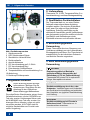
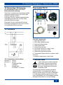
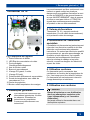
Abb. Gerätekomponenten
1 Gehäuseunterteil
2 LED Schaltzustand Relais
3 Steckbrücke Heizen/Kühlen
4 Drehknopfwelle
5 Anschlussklemme
6 PG-Verschraubung groß, 2 Stück
7 PG-Verschraubung klein
8 Potentiometer Schaltdifferenz
9 Temperaturfühler mit Anschlussleitung 2 m
10 Abdeckung
11 Drehknopf Solltemperatur
1. Allgemeine Hinweise
Diese Anleitung enthält wichtige
Informationen. Befolgen Sie die
Anweisungen. Übergeben Sie die
Anleitung an den Eigentümer.
Diese Anleitung gut aufbewahren.
Die aufgeführten Warnhinweise zeigen Ihnen
Gefahrensituationen, die bei GEFAHR zum
Tod oder ernsten Verletzungen führen oder
bei WARNUNG zum Tod oder ernsten Ver-
letzungen führen könnten, sofern sie nicht
vermieden werden. ACHTUNG steht für
mögliche Sachschäden am Produkt oder
seiner Umgebung.
2. Lieferumfang
Thermostat TH 10 inkl. Temperaturfühler (2 m
Anschlussleitung) und diese Montageanleitung.
3. Qualifikation Fachinstallateur
Der Thermostat darf nur von einer Elektro-
fachkraft entsprechend dieser Anleitung
installiert werden. Sie sind eine Elektrofach-
kraft, wenn Sie aufgrund Ihrer fachlichen
Ausbildung, Schulung und Erfahrung die
elektrischen Anschlüsse gemäß Verdrahtungs-
plan fachgerecht und sicher ausführen können
und Risiken und Gefährdungen durch
Elektrizität erkennen und vermeiden können.
4. Bestimmungsgemäße
Verwendung
Dieser Thermostat dient zur Steuerung von
Ventilatoren abhängig von der Lufttemperatur.
Einsatzgebiet Innenräume. Der Thermostat ist
ausschließlich für den häuslichen Gebrauch
und ähnliche Zwecke vorgesehen.
5. Nicht bestimmungsgemäße
Verwendung
GEFAHR
Explosionsgefahr bei Betrieb in
explosionsfähiger Atmosphäre bei
Entzündung (z. B. bei Funkenbildung).
Thermostat auf keinen Fall in explosions-
fähiger Atmosphäre einsetzen.
ACHTUNG
Gerätebeschädigung durch An- oder
Umbauten. Veränderungen und Umbauten
am Gerät sind nicht zulässig und entbinden
den Hersteller von jeglicher Gewährleistung
und Haftung.
ACHTUNG
Gerätebeschädigung bei Einsatz in
Außenbereichen. Thermostat nur in
Innenbereichen einsetzen.

6. Sicherheitshinweise │ DE
3
6. Sicherheitshinweise
WARNUNG
Gefahren für Personen (auch
Kinder) mit eingeschränkten
physischen, sensorischen
oder psychischen Fähigkei-
ten oder mangelndem Wissen.
Thermostat nur von Perso-
nen, installieren, in Betrieb
nehmen, reinigen und warten
lassen, welche die Gefahren
dieser Arbeiten sicher erken-
nen und vermeiden können.
GEFAHR
Gefahr durch elektrischen
Schlag. Vor Zugang zu den
Anschlussklemmen:
alle Versorgungsstromkreise
freischalten,
benachbarte, unter Span-
nung stehende Teile ab-
decken oder abschranken,
gegen Wiedereinschalten
sichern,
Spannungsfreiheit prüfen.
7. Funktion/Bedienung
Der Thermostat schaltet bei Solltemperatur
einen oder mehrere Ventilatoren ein bzw. aus
‒ je nach Einstellung der Steckbrücke bei
steigender oder sinkender Lufttemperatur
(Kühlen/Heizen).
Die Solltemperatur ist mit Drehknopf [11]
einstellbar. Mit Potentiometer [8] wird die
Schaltdifferenz zwischen Ein-/Ausschalt-
temperatur festgelegt.
8. Technische Daten
Typenschild auf dem Gerät.
Bemessungsspannung
250 V AC
Netzfrequenz
50/60 Hz
Maximalbelastung
(induktive Last)
4 A
Maximalbelastung
(ohmsche Last)
10 A
Schaltdifferenz
0,2 ... 5 K
Funkentstörung
(EN 55011)
VDE 0875,
Störgrad N
Schutzart
IP 54
Schutzklasse
II
Einbauart
Aufputz
Gewicht
0,4 kg
Maße (BxHxT)
125x110x69 mm
9. Umgebungsbedingungen und
Grenzen für den Betrieb
Umgebungstemperatur max. +50 °C
Temperatur-Einstellbereich
-10 bis +30 °C
10. Lagerung
Gerät nur trocken lagern (-20 bis +50 °C).
11. Montage
11.1 Montagehinweise
ACHTUNG
Fehlerhafte Messwerte bei ungeeigne-
tem Montageort. Temperaturfühler [9]
richtig platzieren:
Störeinflüsse vermeiden.
Direkte Sonneneinstrahlung vermeiden.
Nicht im Bereich von Zugluft, heißer
oder kalter Luft (Herd, Heizkörper,
Kühlschrank, Fenster, Lufteinlass
Tellerventil/Innengitter etc.).
Nicht in Baueinheit mit anderen wärme-
erzeugenden Geräten verwenden
(z. B. Dimmer).

DE │ 11. Montage
4
● Gerät nur auf trockenem, ebenen Unter-
grund montieren. Einbaulage beliebig.
● Gerät nur komplett montiert an einer fest
verlegten elektrischen Installation
betreiben.
● Gerät nur mit auf dem Typenschild
angegebener Spannung und Frequenz
betreiben.
● Bei der Elektroinstallation die geltenden
Vorschriften beachten, in Deutschland
insbesondere VDE 0100 mit den
entsprechenden Teilen.
● Klemmbereich der PG-Verschraubungen
[6] geeignet für Anschlussleitungen mit
Außendurchmesser 6 bis 12 mm.
● Temperaturfühler an den beiden Klemmen
„Fühler“ anschließen. Zulässige Leitungen:
max. 100 m lang, 1,5 mm².
● Anschlussklemmen für max. Leitungs-
querschnitt 2,5 mm².
● Eine Vorrichtung zur Trennung vom Netz
mit mindestens 3 mm Kontaktöffnung je
Pol ist vorgeschrieben.
● Betriebsart Kühlen oder Heizen mit
Steckbrücke einstellbar. Anzeige
Schaltzustand mit LED [2].
● Schutzart nur gewährleistet bei
bestimmungsgemäßem Einbau und bei
ordnungsgemäßer Einführung der
Leitungen in das Gehäuse.
11.2 Gerätemontage
1. Versorgungsstromkreise abschalten und
gegen Wiedereinschalten sichern. Warn-
schild sichtbar anbringen.
2. Drehknopf [11] abziehen.
3. Abdeckung [10] entfernen (4 Schrauben).
4. Gehäuseunterteil mit 4 Schrauben an der
Wand befestigen. Geeignetes Befestigungs-
material ist bauseitig bereitzustellen.
5. Mit Steckbrücke [3] die Betriebsart Heizen
oder Kühlen einstellen (ab Werk Heizen).
6. Mit Potentiometer [8] die Schaltdifferenz
zwischen Ein- und Ausschalttemperatur
einstellen (Einstellbereich 0,2…5 K).
ACHTUNG
Kurzschluss durch Nässe bei nicht
ordnungsgemäßer Einführung der
Anschlussleitungen in das Gehäuse.
Darauf achten, dass die Gummidich-
tungen der PG-Verschraubungen die
Anschlussleitungen dicht umschließen.
7. Netz-Anschlussleitung durch PG-Ver-
schraubung [6] und Temperaturfühler-
Anschlussleitung durch PG-Verschrau-
bung [7] in das Gehäuse führen. Die
Anschlussleitungen mit den PG-Ver-
schaubungen sichern (Gummidichtungen
der PG-Verschraubungen müssen die
Anschlussleitungen dicht umschließen).
8. Anschlussleitungen gemäß Schaltbild
( Kapitel 16) verdrahten. Verdrahtung
prüfen, Schrauben der Anschlussklemmen
ggf. nachziehen.
9. Abdeckung [10] anbringen (4 Schrauben)
und Drehknopf [11] aufstecken. Darauf
achten, dass Drehknopfwelle [4] nicht
beschädigt wird und die Gummidichtung
um die Welle dicht sitzt.
10. Ventilator(en) gemäß deren Betriebs-
anleitung installieren.
12. Inbetriebnahme
1. Übereinstimmung mit den technischen
Daten kontrollieren Typenschild.
2. Netzsicherung einschalten Solltemperatur
mit Drehknopf [11] einstellen.
3. Funktionstest durchführen.
13. Reinigung
Gehäuse und Temperaturfühler regelmäßig
mit einem trockenen Tuch reinigen.
14. Störungsbeseitigung
Die Störungsbeseitigung ist nur durch
eine Elektrofachkraft zulässig.
Vor einer Störungsbeseitigung den Relais-
Schaltzustand überprüfen: LED [2] leuchtet
bei angezogenem Relais (Klemme 4 und 5
geschlossen).

15. Demontage, Entsorgung / 1. General notes │ DE/UK
5
15. Demontage, Entsorgung
Die Demontage ist nur durch eine
Elektrofachkraft zulässig.
Das Gerät und auch die Verpackung enthält
wiederverwertbare Stoffe, die nicht in den
Restmüll gelangen dürfen.
Entsorgen Sie die Verpackungsmaterialien
umweltgerecht nach den in Ihrem Land
geltenden Bestimmungen.
Entsorgen Sie das Gerät nach Ende der
Nutzung umweltgerecht nach den in Ihrem
Land geltenden Bestimmungen.
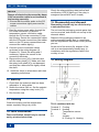
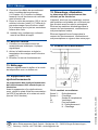
16. Schaltbild
TH 10 kombiniert mit Ventilator
Klemme 3: Kühlen
Klemme 4: Heizen
F Temperaturfühler
M Ventilator
S1 Steckbrücke:
K: Kühlen / H: Heizen
Thermostat TH 10
Fig. Unit components
1 Housing lower part
2 LED relay switching state
3 Heating/cooling jumper
4 Rotary knob shaft
5 Connecting terminal
6 PG screw connection, large, 2 pcs.
7 PG screw connection, small
8 Differential gap potentiometer
9 Temperature sensor with 2 m connect. cable
10 Cover
11 Setpoint temperature rotary knob
1. General notes
These instructions contain important
information. Follow the instructions
given. Pass these instructions onto
the owner. Keep these instructions
somewhere safe.
The warnings provided, indicate hazardous
situations which, if not avoided will result in
death or serious injury in the case of DANGER
or could result in death or serious injury in the
case of WARNING. NOTICE indicates potential
damage to the product or its surroundings.

UK │ 2. Scope of delivery
6
2. Scope of delivery
Thermostat TH 10 incl. temperature sensor
(2 m connection cable) and these mounting
instructions.
3. Specialist installer qualification
The thermostat may only be installed by a
trained electrician, in line with these
instructions. You are deemed competent if
you can competently and safely connect units
to an electrical power supply in line with the
wiring diagram, on the basis of your technical
training and experience and are able to
recognise and avoid risks and dangers
associated with electricity.
4. Intended use
This thermostat is used for controlling fans
depending on the air temperature. For indoor
deployment. The thermostat is only intended
for domestic use and similar purposes.
5. Non-intended use
DANGER
Explosion hazard if operated in an
explosive atmosphere in the case of
ignition, e.g. from sparks.
Never use the thermostat in an explosive
atmosphere.
NOTICE
Unit damage through modifications and
alterations. Modifications and alterations
to the unit are not permitted and release the
manufacturer from any guarantee and
liability.
NOTICE
Damage to the unit when used outdoors.
Only use the thermostat in an indoor
location.
6. Safety instructions
WARNING
Risks for people (including
children) with reduced
physical, sensory or mental
capabilities or a lack of
knowledge.
Thermostat may only be
installed, commissioned,
cleaned and maintained by
people who can safely
recognise and avoid the risks
associated with this work.
DANGER
Danger from electric shock.
Before accessing the
connection terminals:
Switch off all supply circuits.
Cover or block off neigh-
bouring live components
Protect against being acci-
dentally switched back on
Check that there is in fact
no voltage present.
7. Function/Operation
When a setpoint temperature is reached, the
thermostat switches one or more fans on or
off, depending on the settings of the jumpers,
in the case of an increasing or a decreasing
air temperature (cooling/heating).
The setpoint temperature can be set using
the rotary knob [11]. The differential gap
between the on/off temperature is determined
with potentiometer [8].

8. Technical data │ UK
7
8. Technical data
Rating plate on the unit.
Rated voltage
250 V AC
Power frequency
50/60 Hz
Maximum load
(inductive load)
4 A
Maximum load
(ohmic load)
10 A
Differential gap
0.2 ... 5 K
Radio interference
suppression
DIN EN 55011
VDE 0875
Interference level N
Degree of protection
IP 54
Protection class
II
Type of installation
Surface-mounted
Weight
0.4 kg
Dimensions (WxHxD)
125 x 110 x 69 mm
9. Environmental conditions and
operating limits
Ambient temperature:
max. + 50° C
Temperature setting range
-10 to +30 °C
10. Storage
Store unit exclusively in a dry location
(-20 to +50 °C).
11. Mounting
11.1 Mounting instructions
NOTICE
Incorrect measured values can result from
unsuitable installation location. Locate the
temperature sensor [9] correctly.
Avoid disturbing influences.
Avoid exposure to direct sunlight.
Do not use in an area prone to draughts,
hot or cold air, e.g. near stove, fridge,
radiator, refrigerator, air intake, disk
valve/internal grille, etc.
Do not install in a unit with other heat-
generating devices, e.g. a dimmer switch.
● Only install unit onto a dry, level surface.
Any installation position can be selected.
● Only connect the unit to a permanently
wired electrical installation after it has
been completely mounted.
● The unit may only be operated using the
voltage and frequency shown on the rating
plate.
● Be sure to observe the relevant regula-
tions for electrical installation; in Germany
this is particularly VDE 0100, with the
corresponding parts.
● Connection area for the PG screw connec-
tion [6] is suitable for connection cables
with an external diameter of 6 to 12 mm.
● Connect the temperature sensor to both
“sensor” connectors. Permitted cables:
max. 100 m long, 1.5 mm².
● Connection terminals for cable with a max.
cross section of 2.5 mm².
● A mains isolation device with contact
openings of at least 3 mm at each pole is
mandatory.
● Cooling or heating operating mode can be
set with jumpers. Switching state display
with LED [2].
● The degree of protection is only
guaranteed if installation is undertaken
correctly and if the cables are correctly fed
into the housing.
11.2 Unit mounting
1. Switch off power supply circuits and
prevent them from being started up again.
Attach a clearly visible warning sign.
2. Pull the rotary knob [11] off.
3. Remove the cover [10] (4 screws).
4. Use 4 screws to secure the bottom part of
housing to the wall. Suitable mounting
material is to be supplied by the customer.
5. Set the operating mode to heating or
cooling with jumper [3] (factory setting -
heating).
6. Set the differential gap between the on/off
temperature with the potentiometer [8]
(setting range 0.2...5 K).

UK │ 11. Mounting
8
NOTICE
Danger of short-circuits caused by damp
if the connection cable is not inserted in
the housing correctly.
Ensure that the rubber seals on the PG
screw connections tightly surround the
cables.
7. Feed the mains power cable through the
PG screw connection [6] and the
temperature sensor connection cable
through the PG screw connection [7] into
the housing. Secure the connection cables
with the PG screw connections (the rubber
seals on the PG screw connections must
surround the cables tightly).
8. Connect up the connection cables
as shown in the wiring diagram (
Chapter 16). Check the wiring and if
necessary, tighten the screws in the
connection terminals.
9. Remount the cover [10] (4 screws) and
refit the rotary knob [11]. Make sure that
the rotary knob shaft [4] is not damaged
and that the rubber seal fits tightly round
the shaft.
10. Install the fan(s) in accordance with their
operating instructions.
12. Start-up
1. Check that the technical data has been
adhered to rating plate.
2. Switch the mains fuse on. Set the setpoint
temperature using the rotary knob [11].
3. Run function test.
13. Cleaning
Clean the housing and the temperature
sensor regularly using a dry cloth.
14. Fault rectification
Fault rectification should only be carried
out by a trained electrician.
Check the relay switching state before fault
rectification: LED [2] lights up if the relay is
energised (terminals 4 and 5 closed).
15. Disassembly and disposal
Dismantling should only be carried out by
a trained electrician.
The unit and the packaging contain parts that
can be recycled, and should not end up in the
domestic waste.
Dispose of the packaging material in an
environmentally-friendly way, in compliance
with the regulations valid in the country where
you are.
At the end of its service life, dispose of the
unit in an environmentally-friendly way, in
compliance with the regulations valid in the
country of use.
16. Wiring diagram
TH 10 combined with fan
Terminal 3 Cooling
Terminal 4 Heating
F Temperature sensor
M Fan
S1 Jumper:
K: Cooling / H: Heating

1. Remarques générales │ FR
9
Thermostat TH 10
Fig. Composants de l'appareil
1 Partie inférieure du boîtier
2 LED État de commutation du relais
3 Pont enfichable
Chauffage/Refroidissement
4 Axe du bouton rotatif
5 Borne de raccordement
6 Vissage PG grand, 2 unités
7 Vissage PG petit
8 Potentiomètre différence de commutation
9 Sonde de température avec câble de
raccordement, 2 m
10 Cache de protection
11 Bouton rotatif température de consigne
1. Remarques générales
Ces instructions contiennent des
informations importantes. Veuillez
les observer. Remettez les
instructions au propriétaire.
Conservez précieusement ces
instructions.
Les avertissements qu'elles contiennent vous
mettent en garde contre les situations
dangereuses susceptibles d'entraîner la mort
en cas de DANGER ou de graves blessures
en cas d'AVERTISSEMENT, dans la mesure
où elles ne sont pas évitées. ATTENTION
signale des endommagements possibles
du produit ou de son environnement.
2. Volume de fourniture
Thermostat TH 10, y compris sonde de
température (2 m de câble de raccordement)
et la présente notice de montage.
3. Qualification de l'installateur
spécialisé
L'installation du thermostat est exclusivement
réservée à un électricien qualifié et doit être
effectuée conformément aux présentes
instructions. On entend par électricien qualifié
une personne qui, par son apprentissage, sa
formation et son expérience, est capable
d'exécuter les branchements électriques
selon le schéma de câblage et en toute
sécurité, connaît les dangers de l'électricité
et peut les éviter.
4. Utilisation conforme
Ce thermostat sert à commander des
ventilateurs en fonction de la température de
l'air. Il est conçu pour être utilisé à l'intérieur.
Ce thermostat est exclusivement réservé à
l'usage domestique et similaires.
5. Utilisation non conforme
DANGER
Risque d'explosion en cas d'utilisation
dans une atmosphère explosive suite
à une inflammation (p. ex. formation
d'étincelles).
Ne jamais utiliser le thermostat dans une
atmosphère explosive.

FR │ 5. Utilisation non conforme
10
ATTENTION
Endommagement de l'appareil suite à
modifications ou transformations. Les
modifications et transformations apportées
sur l'appareil sont rigoureusement interdites
et dégagent le fabricant de toute
responsabilité et garantie.
ATTENTION
Endommagement de l'appareil en cas
d'utilisation à l'extérieur. Utiliser le
thermostat exclusivement à l'intérieur.
6. Consignes de sécurité
AVERTISSEMENT
Danger pour les personnes
(y compris les enfants) ayant
des capacités physiques,
sensorielles ou psychiques
réduites ou sans connais-
sances suffisantes.
L'installation, la mise en ser-
vice, le nettoyage et l'entretien
du thermostat ne pourront être
effectués que par des person-
nes conscientes des risques
présentés par ces travaux et
en mesure de les éviter.
DANGER
Risque d'électrocution.
Avant d'accéder aux bornes
de raccordement :
couper tous les circuits
d'alimentation électrique,
recouvrir ou isoler les pièces
adjacentes sous tension,
les protéger contre une
remise en marche inopinée,
contrôler l'absence de
tension.
7. Fonctionnement / Commande
À la température de consigne, le thermostat
active / désactive un ou plusieurs ventilateurs
‒ en fonction du réglage du pont enfichable,
avec une température de l'air ascendante ou
descendante (Refroidissement/Chauffage).
La température de consigne est réglable par
le biais du bouton rotatif [11]. Avec le poten-
tiomètre [8], on détermine la différence de
commutation entre température d'activation
et de désactivation.
8. Caractéristiques techniques
Plaque signalétique sur l'appareil.
Tension de service
250 VCA
Fréquence du secteur
50/60 Hz
Charge maximale
(charge inductive)
4 A
Charge maximale
(charge ohmique)
10 A
Différence de commutation
0,2 ... 5 K
Antiparasitage
(EN 55011)
VDE 0875, degré
de parasitage N
Type de protection
IP 54
Classe de protection
II
Type de montage
Montage
apparent
Poids
0,4 kg
Dimensions (lxhxp)
125x110x69 mm
9. Conditions ambiantes et limites
d'utilisation
Température ambiante
+50 °C max.
Plage de réglage de la
température
-10 à +30 °C

10. Stockage | FR
10. Stockage
Stockage uniquement dans un endroit sec
(de -20 à +50 °C).
11. Montage
11.1 Consignes de montage
ATTENTION
Valeurs de mesure erronées en raison
d'un emplacement de montage
inapproprié. Positionner correctement
la sonde de température [9] :
Éviter les facteurs de perturbation.
Éviter l'impact direct des rayons du soleil.
Ne pas installer dans une zone de cou-
rant d'air, d'air chaud ou froid (cuisinière,
radiateur, réfrigérateur, fenêtre, entrée
d'air par bouche d'extraction-
insufflation/grille intérieure, etc.).
Ne pas utiliser dans la même unité de
montage que des appareils générateurs
de chaleur (p. ex. variateur).
● Monter l'appareil exclusivement sur une
base sèche et plane. Position d'installation
au choix.
● N'utiliser l’appareil que s'il est
complètement monté sur une installation
électrique permanente.
● L'appareil ne doit fonctionner qu'à la
tension et à la fréquence indiquées sur la
plaque signalétique.
● La réglementation en vigueur pour
l'installation électrique et notamment, pour
l'Allemagne, la norme DIN VDE 0100 et
les parties correspondantes, doivent être
respectées.
● La zone de serrage des vissages PG [6]
convient à des câbles de raccordement de
diamètre extérieur compris entre 6 et 12 mm.
● Connecter la sonde de température sur les
deux bornes « Sonde ». Câbles ad-
missibles : longueur max. 100 m, 1,5 mm².
● Bornes de raccordement pour section de
câble max. 2,5 mm².
● Prévoir un dispositif de coupure du secteur
avec une ouverture de contact d'au moins
3 mm par pôle.
● Mode de fonctionnement Refroidissement ou
Chauffage réglable par pont enfichable. Af-
fichage de l'état de commutation par LED [2].
● Le type de protection n'est assuré que si
le montage est effectué selon les
instructions et si les câbles ont été
introduits correctement dans le boîtier.
11.2 Montage de l'appareil
1. Couper les circuits d'alimentation
électrique et s'assurer qu'ils ne peuvent
être remis en marche par inadvertance.
Apposer un panneau d'avertissement de
manière bien visible.
2. Déposer le bouton rotatif [11].
3. Enlever le cache de protection [10] (4 vis).
4. Fixer la partie inférieure du boîtier sur le
mur avec 4 vis. Le matériel de fixation
adéquat est à fournir par le client.
5. Avec le pont enfichable [3], régler le mode
de fonctionnement Chauffage ou Refroidis-
sement (réglage par défaut Chauffage).
6. Avec le potentiomètre [8], régler la
différence de commutation entre la
température d'activation/de désactivation
(plage de réglage 0,2…5 K).
ATTENTION
Risque de court-circuit par humidité
suite à une insertion incorrecte des
câbles de raccordement dans le boîtier.
Veiller à ce que les joints en caoutchouc
des vissages PG enserrent fermement
les câbles de raccordement.
7. Introduire le câble de raccordement au
secteur à travers le vissage PG [6] et le
câble de raccordement de la sonde de
température à travers le vissage PG [7]
dans le boîtier. Serrer les câbles de
raccordement avec les vissages PG (les
joints en caoutchouc des vissages PG
doivent enserrer fermement les câbles de
raccordement).

FR | 11. Montage
8. Connecter les câbles de raccordement
selon le schéma de branchement
( Chapitre 16). Contrôler le câblage,
resserrer les vis des bornes de raccorde-
ment si besoin est.
9. Poser le cache de protection [10] (4 vis) et
enficher le bouton rotatif [11]. Veiller à ne
pas endommager l'axe du bouton rotatif
[4] et s'assurer que le joint en caoutchouc
enserre bien l'axe.
10. Installer le(s) ventilateur(s) conformé-
ment à leur Mode d'emploi
12. Mise en service
1. Contrôler la concordance avec les
caractéristiques techniques plaque
signalétique.
2. Activer le fusible secteur et régler la
température de consigne avec le bouton
rotatif [11].
3. Effectuer un test de fonctionnement.
13. Nettoyage
Nettoyer régulièrement le boîtier et la sonde
de température avec un chiffon sec.
14. Suppression des
dysfonctionnements
La suppression des dysfonctionnements
doit exclusivement être effectuée par un
électricien.
Avant la suppression d'un dysfonctionne-
ment, vérifier le relais d'état de commutation :
La LED [2] est allumée si le relais est excité
(bornes 4 et 5 fermées).
15. Démontage, élimination
Le démontage doit exclusivement être
effectué par un électricien.
L'appareil, ainsi que son emballage, contient
des matériaux recyclables qui ne doivent pas
être éliminés avec les ordures ménagères.
Éliminez les matériaux d’emballage dans le
respect de l'environnement, conformément
aux prescriptions locales.
Éliminez l'appareil hors d'usage dans le
respect de l'environnement, conformément
aux prescriptions en vigueur dans votre pays.
16. Schéma de branchement
TH 10 combiné au ventilateur
Borne 3 : Refroidissement
Borne 4 : Chauffage
F Sonde de température
M Ventilateur
S1 Pont enfichable :
K : Refroidissement /
H : Chauffage
Maico Elektroapparate-Fabrik GmbH • Steinbeisstr. 20 • 78056 Villingen-Schwenningen •
Germany • Service +49 7720 6940 • technik@maico.de
10.16_Es
0185.0884.0002_RLF.6_10.16_DSW
-
 1
1
-
 2
2
-
 3
3
-
 4
4
-
 5
5
-
 6
6
-
 7
7
-
 8
8
-
 9
9
-
 10
10
-
 11
11
-
 12
12


in anderen Sprachen
- English: Maico TH 10
- français: Maico TH 10
Verwandte Artikel
Andere Dokumente
-
Dimplex LA 8MR Bedienungsanleitung
-
-
Dimplex WPM 2006 R Installation And Start-Up Instructions Manual
-
-
-
Renkforce UT300 Bedienungsanleitung
-
-
-
H-Tronic TSM 125 Benutzerhandbuch