Peavey PV 8 Benutzerhandbuch
- Kategorie
- Zusätzliche Musikausrüstung
- Typ
- Benutzerhandbuch
Dieses Handbuch ist auch geeignet für

PV
®
8
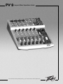
Compact Mixer Operations Guide
For more information on other great Peavey products, go to your local Peavey dealer or online at www.peavey.com

2
Intended to alert the user to the presence of uninsulated “dangerous voltage” within the product’s
enclosure that may be of sufficient magnitude to constitute a risk of electric shock to persons.
Intended to alert the user of the presence of important operating and maintenance (servicing)
instructions in the literature accompanying the product.
CCAAUUTTIIOONN::
Risk of electrical shock — DO NOT OPEN!
CCAAUUTTIIOONN::
To reduce the risk of electric shock, do not remove cover. No user serviceable parts inside.
Refer servicing to qualified service personnel.
WWAARRNNIINNGG::
To prevent electrical shock or fire hazard, do not expose this appliance to rain or moisture.
Before using this appliance, read the operating guide for further warnings.
Este símbolo tiene el propósito, de alertar al usuario de la presencia de “(voltaje) peligroso” sin
aislamiento dentro de la caja del producto y que puede tener una magnitud suficiente como para
constituir riesgo de descarga eléctrica.
Este símbolo tiene el propósito de alertar al usario de la presencia de instruccones importantes sobre la
operación y mantenimiento en la información que viene con el producto.
PPRREECCAAUUCCIIOONN::
Riesgo de descarga eléctrica ¡NO ABRIR!
PPRREECCAAUUCCIIOONN::
Para disminuír el riesgo de descarga eléctrica, no abra la cubierta. No hay piezas útiles
dentro. Deje todo mantenimiento en manos del personal técnico cualificado.
AADDVVEERRTTEENNCCIIAA::
Para evitar descargas eléctricas o peligro de incendio, no deje expuesto a la lluvia o
humedad este aparato Antes de usar este aparato, Iea más advertencias en la guía de operación.
Ce symbole est utilisé dans ce manuel pour indiquer à l’utilisateur la présence d’une tension dangereuse
pouvant être d’amplitude suffisante pour constituer un risque de choc électrique.
Ce symbole est utilisé dans ce manuel pour indiquer à l’utilisateur qu’il ou qu’elle trouvera d’importantes
instructions concernant l’utilisation et l’entretien de l’appareil dans le paragraphe signalé.
AATTTTEENNTTIIOONN::
Risques de choc électrique — NE PAS OUVRIR!
AATTTTEENNTTIIOONN::
Afin de réduire le risque de choc électrique, ne pas enlever le couvercle. Il ne se trouve à
l’intérieur aucune pièce pouvant être reparée par l’utilisateur. Confiez I’entretien et la réparation de
l’appareil à un réparateur Peavey agréé.
AAVVEERRTTIISSSSEEMMEENNTT
: Afin de prévenir les risques de décharge électrique ou de feu, n’exposez pas cet
appareil à la pluie ou à l’humidité. Avant d’utiliser cet appareil, lisez attentivement les avertissements
supplémentaires de ce manuel.
Dieses Symbol soll den Anwender vor unisolierten gefährlichen Spannungen innerhalb des Gehäuses
warnen, die von Ausreichender Stärke sind, um einen elektrischen Schlag verursachen zu können.
Dieses Symbol soll den Benutzer auf wichtige Instruktionen in der Bedienungsanleitung aufmerksam
machen, die Handhabung und Wartung des Produkts betreffen.
VVOORRSSIICCHHTT::
Risiko — Elektrischer Schlag! Nicht öffnen!
VVOORRSSIICCHHTT::
Um das Risiko eines elektrischen Schlages zu vermeiden, nicht die Abdeckung enfernen. Es
befinden sich keine Teile darin, die vom Anwender repariert werden könnten. Reparaturen nur von
qualifiziertem Fachpersonal durchführen lassen.
AACCHHTTUUNNGG::
Um einen elektrischen Schlag oder Feuergefahr zu vermeiden, sollte dieses Gerät nicht dem
Regen oder Feuchtigkeit ausgesetzt werden. Vor Inbetriebnahme unbedingt die Bedienungsanleitung lesen.

3
IIMMPPOORRTTAANNTT SSAAFFEETTYY IINNSSTTRRUUCCTTIIOONNSS
WWAARRNNIINNGG::
When using electrical products, basic cautions should always be followed, including the following:
1. Read these instructions.
2. Keep these instructions.
3. Heed all warnings.
4. Follow all instructions.
5. Do not use this apparatus near water.
6. Clean only with a dry cloth.
7. Do not block any of the ventilation openings. Install in accordance with manufacturer’s instructions.
8. Do not install near any heat sources such as radiators, heat registers, stoves or other apparatus (including
amplifiers) that produce heat.
9. Do not defeat the safety purpose of the polarized or grounding-type plug. A polarized plug has two blades with one
wider than the other. A grounding type plug has two blades and a third grounding plug. The wide blade or third
prong is provided for your safety. If the provided plug does not fit into your outlet, consult an electrician for
replacement of the obsolete outlet.
10. Protect the power cord from being walked on or pinched, particularly at plugs, convenience receptacles, and the
point they exit from the apparatus.
11. Note for UK only: If the colors of the wires in the mains lead of this unit do not correspond with the terminals in your
plug‚ proceed as follows:
a) The wire that is colored green and yellow must be connected to the terminal that is marked by the letter E‚ the
earth symbol‚ colored green or colored green and yellow.
b) The wire that is colored blue must be connected to the terminal that is marked with the letter N or the color black.
c) The wire that is colored brown must be connected to the terminal that is marked with the letter L or the color red.
12. Only use attachments/accessories provided by the manufacturer.
13. Use only with a cart, stand, tripod, bracket, or table specified by the manufacturer, or sold with the apparatus. When
a cart is used, use caution when moving the cart/apparatus combination to avoid injury from tip-over.
14. Unplug this apparatus during lightning storms or when unused for long periods of time.
15. Refer all servicing to qualified service personnel. Servicing is required when the apparatus has been damaged in
any way, such as power-supply cord or plug is damaged, liquid has been spilled or objects have fallen into the
apparatus, the apparatus has been exposed to rain or moisture, does not operate normally, or has been dropped.
16. Never break off the ground pin. Write for our free booklet “Shock Hazard and Grounding.” Connect only to a power
supply of the type marked on the unit adjacent to the power supply cord.
17. If this product is to be mounted in an equipment rack, rear support should be provided.
18. Exposure to extremely high noise levels may cause a permanent hearing loss. Individuals vary considerably in
susceptibility to noise-induced hearing loss, but nearly everyone will lose some hearing if exposed to sufficiently
intense noise for a sufficient time. The U.S. Government’s Occupational and Health Administration (OSHA) has
specified the following permissible noise level exposures:
Duration Per Day In Hours Sound Level dBA, Slow Response
890
692
495
397
2 100
1
1
⁄
2
102
1 105
1
⁄
2
110
1
⁄
4
or less 115
According to OSHA, any exposure in excess of the above permissible limits could result in some hearing loss. Ear plugs or protectors to the
ear canals or over the ears must be worn when operating this amplification system in order to prevent a permanent hearing loss, if exposure
is in excess of the limits as set forth above. To ensure against potentially dangerous exposure to high sound pressure levels, it is
recommended that all persons exposed to equipment capable of producing high sound pressure levels such as this amplification system be
protected by hearing protectors while this unit is in operation.
SSAAVVEE TTHHEESSEE IINNSSTTRRUUCCTTIIOONNSS!!

4
PV
®
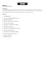
8Compact Mixer
Description
Congratulations on purchasing the Peavey PV8 compact mixer. The PV8 is a studio-quality mixing console designed to meet diverse
needs while occupying only a small space. This is the perfect console for small venue performances or home recording environments.
Please read this guide carefully to ensure your personal safety as well as the safety of your equipment.
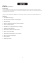
Features
➡ Four XLR Mic inputs
➡ Two stereo channels with RCA and
1
⁄4" inputs
➡ Three-band channel EQ
➡ A/B stereo input selector reduces patching
➡ Inserts on all mono channels
➡ Clip LEDs that thoroughly monitor clipping
➡ 48V phantom power switch
➡ Effects send on every channel with stereo return
➡ Monitor send on every channel
➡ Zero latency record monitoring capabilities
➡ Control room output with level control
➡ Contour control switch
➡ 80 Hz low-cut switch
EENNGGLLIISSHH

5
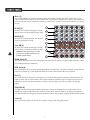
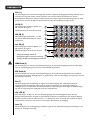
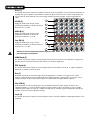
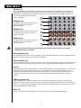
Gain (1)
This control establishes the nominal operating level for the channel. The input gain can be adjusted over a wide
range to compensate for soft voices or very loud drums. To maximize the signal-to-noise ratio the gain should be set
to the proper level with the channel level control (9) set to 0. If the clip LED comes on and remains lit, try reducing
the gain.
Hi EQ (2)
An active tone control (shelving type: ±15 dB)
that varies the level of the high frequency range.
Mid EQ (3)
An active tone control (peak dip: ±15 dB) that
varies the mid frequency range.
Low EQ (4)
An active tone control (shelving type: ±15 dB)
that varies the level of the low frequency range.
Caution: Excessive low frequency boost causes
greater power consumption and increases the
possibility of speaker damage.
MON Send (5)
This control adjusts the level of the channel signal sent to the monitor output. The signal is taken before the channel
level control but after the channel EQ.
EFX Send (6)
This control adjusts the level of the channel signal added to the effects mix. The effects send signal is taken after the
channel level controls (9) so that adjustments made to the level control will also affect the send level.
Pan (7)
This knob controls the placement of the signal in the stereo field. When rotated completely counterclockwise‚ the
signal is present only on the left channel; when rotated completely clockwise‚ only in the right channel. On stereo
channels 5/6 and 7/8, this control functions as a balance control to adjust the relative level of the left and right
signals.
Clip LED (8)
This light normally indicates that the channel signal level is nearing the overload point. The clip indicator circuit
monitors the signal at many points in the channel to ensure that it catches all instances of clipping. It illuminates at
+19 dBu and warns that the gain or EQ boost should be reduced. When it lights, roughly 3 dB of headroom remain.
Level (9)
This is the channel output level control. The optimum setting is the 0 (unity gain) position.
FF RR OO NN TT PP AA NN EE LL
1
2
3
5
6
8
9
4
7

6
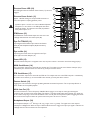
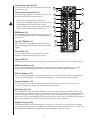
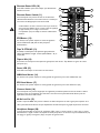
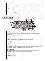
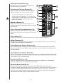
Phantom Power LED (10)
This LED lights when the Phantom Power Switch (11) has been
engaged.
Phantom Power Switch (11)
Applies +48 VDC Voltage to the input XLR connectors to
power microphones requiring phantom power.
If phantom power is used, do not connect unbalanced dynamic
microphones or other devices to the XLR inputs that cannot
handle this Voltage. The Phantom Power LED (10) indicates
when phantom power is on.
EFX/Return (12)
The EFX/Return Level Control adjusts the level sent to the
Left/Right main bus from the return inputs (30).
Tape To CTRL/HP (13)
Depressing this switch adds the tape return to the Control
Room (32) and Headphone Outputs (20) for zero latency
monitoring.
Tape to Mix (14)
Depressing this switch routes the signal from the Tape
Inputs (38) to the Main Outputs (31).
Power LED (15)
This LED indicates AC power is supplied to the unit‚ the power switch is on and the unit is functioning properly.
MON Send Master (16)
This is the master output level control for the monitor mix. The output level sent to the Monitor Send jack (33) is
controlled by the channel monitor send controls (5) and by this master control.
EFX Send Master (17)
This is the master output level control for the EFX mix. The output level sent to the EFX Send jack is controlled by
the channel level controls (9), the channel EFX send controls (6) and by this master control.
Contour Switch (18)
Engaging this switch enhances the signal by adding both bass and treble frequencies. This is especially effective at
lower volumes or for tape/CD playback.
80 Hz Low Cut (19)
The Low Cut filter has a corner frequency of 80 Hz. When engaged‚ it can improve clarity by removing low
frequencies that can make a mix sound muddy. This feature is especially useful when playing outside on a windy day
or on a hollow‚ noisy stage. These kinds of ambient noises can rob your sound system of power. Engaging this switch
will remove those frequencies from the system and restore power to where it’s needed.
Headphone Output (20)
The Headphone Output is a
1
⁄4
"
TRS (tip= left; ring = right; sleeve = ground). The signal sent to this output is
normally the Left/Right mix. When the Tape to Control Room switch is engaged, the tape input signal is added to the
Left/Right mix and can be monitored in the headphones.
10
11
12
13
14
15
16
17
18
19
20
21
22
23

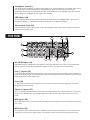
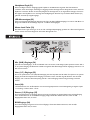
Mic (XLR) Inputs (24)
XLR balanced inputs optimized for a microphone or other low impedance source. Pin 2 is the positive input.
Because of the wide range of gain adjustment, signal levels up to +14 dBu can be accommodated.
Line (
1
⁄4”) Inputs (25)
1
⁄4” balanced (TRS) 10 k Ohm impedance input. The tip is the positive input and should be used for unbalanced
inputs. It has 20 dB less gain than the XLR input and does not have phantom power available. The Mic and Line
inputs should not be used simultaneously.
Insert (26)
1
⁄4” TRS Connector allows external signal processors to be inserted into the channel signal path. Tip=Send;
Ring=Return; Sleeve=Ground.
Stereo (
1
⁄4") Inputs (27)
These
1
⁄4" unbalanced inputs work as a stereo line input using both jacks or as a mono input if the connection is
made to the Left/Mono input only. The A/B input selector must be in the "A" position for these jacks to be
active.
RCA Inputs (28)
These RCA inputs work as stereo line inputs. The A/B input selector must be in the "B" position for these jacks
to be active.
A/B Switch (29)
The A/B input selector switch expands the capability of the PV
®
8 mixer by allowing two stereo sources to be
connected to each stereo line input. Instead of re-patching, the switch selects which input jacks are active.
Headphone Level (21)
This knob sets the headphone and control room output levels. To avoid damage to your hearing‚ make sure to
turn the dial fully counterclockwise before using headphones. Slowly turn the knob clockwise until a
comfortable listening level is set. Normally, the signal in the headphones is the Left/Right signal. If the Tape to
Control Room (13) is engaged‚ the tape signal is also included.
LED Meters (22)
Two six-segment LED arrays are provided to monitor the levels of the main Left/Right outputs. These meters
range from -20 dB to +19 dB. 0 dB on the meter corresponds to +4 dBu at the outputs.
Master Level Fader (23)
The Master Fader controls the level sent to the main Left/Right outputs. Best results are obtained when this
control is set near the 0 point.
7
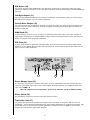
RR EE AA RR PP AA NN EE LL
24
25
26
27
30
28
29
32 34
33
31

EFX Return (30)
The EFX Return inputs (Left/Mono‚ Right) feature two
1
⁄4" TS jacks. These inputs can be used with Tip‚ Ring, Sleeve
(TRS) balanced or Tip, Sleeve (TS) unbalanced connectors. The EFX Return is controlled via the EFX/Return Level
Control (19).
Left/Right Outputs (31)
The Left/Right Outputs feature two
1
⁄4" TRS Z-balanced jacks. These outputs can be used with Tip‚ Ring, Sleeve
(TRS) balanced or Tip, Sleeve (TS) unbalanced connectors.
Control Room Outputs (32)
The Control Room Outputs feature two
1
⁄4" TRS Z-balanced jacks. These outputs can be used with Tip, Ring, Sleeve
(TRS) balanced or Tip, Sleeve (TS) unbalanced connectors. The Control Room Output Level is adjusted with the
Headphone Level Control (21).
MON Send (33)
The MON Send features a
1
⁄4" TRS Z-balanced jack in the master section. This output can be used with the Tip,
Ring, Sleeve (TRS) balanced or Tip, Sleeve (TS) unbalanced connectors. The MON mix is determined by the
amount of signal being sent to the MON bus in each channel and by the Monitor master control.
EFX Send (34)
The EFX Send features a
1
⁄4" TRS Z-balanced jack in the master section. These outputs can be used with Tip‚ Ring,
Sleeve (TRS) balanced or Tip, Sleeve (TS) unbalanced connectors. The EFX mix is determined by the amount of
signal being sent to the EFX bus in each channel and by the EFX Master Control.
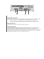
Power Adapter Input (35)
Use to connect the included power supply. Be sure the power supply is connected to the PV
®
8 before connecting
to a power source. Use 16 VAC 1 A adapter only.
Note: Replace only with Peavey part number 70902571 for Domestic or 70902572 for Export.
Power Switch (36)
Depressing the power switch supplies power to the unit.
Tape In/Out (38 & 37)
The tape input jacks are designed to accommodate tape‚ CD or computer sound card output levels. The output
level is +4 dBu for connection to a recorder or sound card input. The tape inputs can be used as an additional
stereo input by engaging the Tape to Main Mix switch (14). The tape input can also be used to monitor the
recorder/sound card output without the risk of feedback.
8
35
36
37
38

9
PAN
Meridian, MS 39301
Peavey Electronics Corp.
P. O. Box 2898
Sheet Title:
Title:
Sheet
Date:
of
B
A
21
B
A
21
C
4
HI PASS
HI PASS
+48V
BALANCE
CONTOUR
LO HI
CONTOUR
LO HI
EQ
LO MID HI
EQ
LO MID HI
EQ
LO MID HI
+
-
RIGHT
TAPE -L/R SELECT
POWER
PHANTOM
RIGHT
LEFT
LINE
RIGHT
LEFT
XLR
LEVEL
EFX RETURN
LEFT/MONO
RIGHT
TAPE OUTPUT
HEADPHONES
CONTROL ROOM
TAPE TO MIX
LEFT
RIGHT
MAIN OUTPUTS
TAPE INPUT
GLOBAL
CONTROL ROOM
TAPE TO
GAIN
INSERT
CLIP
EFX
MON
EFX
MON
LEFT/MONO
RIGHT
EFX
MON
LEFT
SELECT
INPUT
EFX SEND
MON SEND
CLIP
LED METER
MONO INPUT CHANNEL 1-4
STEREO INPUT CHANNEL 5/6 - 7/8
2
3
1
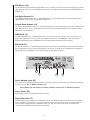
PV8_BLOCK
4-9-2004_11:2522
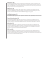
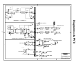
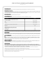
PV
®
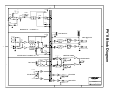
8 Block Diagram

10
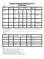
PPVV
®
88 CCoommppaacctt CCoonnssoollee
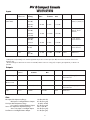
SSPPEECCIIFFIICCAATTIIOONNSS
Function
Microphone
(150 Ohms)
Line (10 k Ohms)
Stereo Line Input
Aux Returns
Tape
Input Z
(Ohms min)
2.2 k
10 k
10 k
10 k
10 k
Input Gain
Setting
Max Gain
(63 dB)
Min Gain
(10 dB)
Max Gain
(43 dB)
Min Gain
(-10 dB)
Max Gain
(20 dB)
Nominal
N/A
(0 dB)
N/A
(10 dB)
Nominal*
-59 dBu
-6 dBu
-39 dBu
+14 dBu
+16 dBu
-2 dBu
+4 dBu
-10 dBV
Max
-41 dBu
+12 dBu
-21 dBu
+32 dBu
+2 dBu
+16 dBu
+22 dBu
+12 dBu
Bal/Unbal
Bal
Bal
Unbal
Unbal
Unbal
Connector
XLR Pin 1 Gnd
Pin 2 (+)‚ Pin 3 (-1)
1
⁄
4"
TRS; Tip (+)‚
Ring (-)‚ Sleeve
Ground
1
⁄4" TS; Tip (+)‚
Sleeve Ground
1
⁄4" TRS; Tip (+)‚
Sleeve Ground
RCA Phono
Input Levels
Min**
-83 dBu
-30 dBu
-63 dBu
-10 dBu
-40 dBu
-26 dBu
-17 dBu
-17 dBu
Function
Main Left/Right
Effects and
Monitor Sends
Headphone
Tape
Min Load Z
(Ohms)
600
600
8
2.2 k
Nominal
+4 dBu
+4 dBu
+4 dBu (no load)
+4 dBu
Max
+22 dBu
+22 dBu
+22 dBu
+22 dBu
Bal/Unbal
Bal
Bal
Unbal
Unbal
Connector
1
⁄4" TRS: Tip (+), Ring (-),
Sleeve Ground
1
⁄4" TS, Tip (+)‚ Sleeve Ground
1
⁄4" TRS; Tip Left‚ Ring Right‚
Sleeve Ground
RCA Phono
Output Level
0 dBu = 0.775 V (RMS)
** Min Input Level (sensitivity) is the smallest signal that will produce nominal output (+4 dBu) with channel and master faders set for
maximum gain.
* Nominal settings are defined as all controls set at 0 dB (or 50% rotation for rotary pots) except the gain adjustment pot which is as
specified.
0 dBu = 0.775 V (RMS)
Inputs
Outputs
Gain
Mic Input Gain Adjustment Range: 10 dB to 60 dB
Mic Input to Left/Right Balance Output 87 dB (max gain)
Line Input Gain Adjustment Range: -10 dB to 40 dB
Line Input to Left/Right Balance Output 67 dB (max gain)
Stereo Line Input Gain Adjustment Range: Off to +20 dB
Stereo Line Input to Left/Right Output 44 dB (max gain)
Aux Return to Left/Right Balance Output 21 dB (max gain)

11
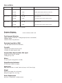
Output
Master Left/Right
Monitor Send
Effects Sends
Residual Noise
-98 dBu
-90 dBu
-84 dBu
-103 dBu
-84 dBu
-103 dBu
-84 dBu
S/N Ratio (Ref: +4 dBu)
102 dB
94 dB
90 dB
107 dB
88 dB
107 dB
88 dB
Test Conditions
Master Fader Down‚ Channel Levels Down
Master Fader Nominal‚ Channel Levels Down
All controls nominal‚ mic gain minimum
All controls off
All channel sends nominal, masters nominal
All controls off
All channel sends nominal, masters nominal
(Hum and noise measurements: 22 Hz to 22 kHz BW)
Frequency Response
Mic Input to Left/Right Output 14 Hz to 25 kHz +0 dB/-1 dB
Total Harmonic Distortion
<0.01% 20 Hz to 20 kHz Mic to Left/Right Output (10 Hz to 80 kHz BW)
<0.005% Typical
<0.0007% Mic Pre-amp Distortion
Equivalent Input Noise (EIN)
-129 dBu (input terminated with 150 Ohms)
Crosstalk
>80 dB Adjacent Input Channels (1 kHz)
>75 dB Left to Right Outputs (1 kHz)
Common Mode Rejection Ratio (Mic Input)
50 dB minimum (20 Hz to 20 kHz)
70 dB typical @ 1 kHz
Meters
6 segment, peak reading (0 dB = +4 dBu)
Signal/Overload Indicators
Red LED lights 3 dB below clipping
Dimensions
9.32" (23.7 cm) wide x 11.625" (29.5 cm) deep x 2.76" (7.0 cm) high
Weight
Without power supply: 5.7 lbs. (2.58 kg)
With power supply: 7 lbs. (3.17 kg)
Power Requirements
Domestic: 16 VAC 60 Hz; 12 Watts nominal
Hum and Noise

12
PV
®
8Kompakt-Mischpult
Beschreibung
Herzlichen Glückwunsch! Sie haben gerade ein Peavey PV8 Kompakt-Mischpult erworben. Der PV8 ist ein Mischpult, das trotz
seiner geringen Maße Studioqualität liefert und die verschiedensten Bedürfnisse erfüllt. Der PV8 ist das perfekte Mischpult für kleine
Veranstaltungen oder das Heimstudio.
Lesen Sie sich diese Anleitung bitte sorgfältig durch, damit sowohl Ihre Sicherheit als auch die Ihrer Ausrüstung gewährleistet ist.
Merkmale
➡ Vier XLR-Mikrofoneingänge
➡ Zwei Stereo-Kanäle mit Cinch- und 1/4"-Eingängen
➡ 3-Band-Kanal-EQ
➡ A/B-Stereo-Eingangswahlschalter für weniger Verkabelung
➡ Inserts an allen Monokanälen
➡ Clip-LEDs für die sorgfältige Überwachung von Clipping
➡ 48-V-Phantomspeisung-Schalter
➡ Effects Send an jedem Kanal mit Stereo Return
➡ Monitor Send an jedem Kanal
➡ Aufnahmeüberwachungsfunktionen ohne Latenzzeit
➡ Abhörraumausgang mit Pegelregler
➡ Contour-Schalter
➡ 80-Hz-Tiefpassschalter
DDEEUUTTSSCCHH

13
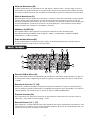
VV OO RR DD EE RR SS EE II TT EE
Gain (1)
Mit diesem Regler wird der Nennbetriebspegel für den Kanal eingestellt. Die Eingangsverstärkung kann über einen
weiten Bereich eingestellt werden, um zarte Stimmen oder sehr laute Drums zu kompensieren. Um den
Rauschabstand zu maximieren, sollte die Verstärkung auf den korrekten Pegel mit dem Kanal-Pegelregler (9) auf 0
gestellt werden. Leuchtet die Clip-LED kontinuierlich auf, sollte die Verstärkung verringert werden.
Hi EQ (2)
Aktiver Klangregler (stufenlos regelbar: ±15
dB), mit dem der Pegel im
Hochfrequenzbereich variiert werden kann.
Mid EQ (3)
Aktiver Klangregler (Spitze/Kerbe: ±15 dB),
mit dem der Mittenfrequenzbereich variiert
werden kann.
Low EQ (4)
Aktiver Klangregler (stufenlos regelbar: ±15
dB), mit dem der Pegel im
Niederfrequenzbereich variiert werden kann.
Achtung: Ein übermäßiges Anheben der
Niederfrequenzen führt zu erhöhtem Stromverbrauch
und steigert das Risiko einer Beschädigung der Lautsprecher.
MON Send (5)
Mit diesem Regler wird der Pegel des Kanalsignals festgelegt, das zum Monitorausgang gesendet wird. Das Signal
wird vor dem Kanalpegelregler, jedoch hinter dem Kanal-EQ abgenommen.
EFX Send (6)
Mit diesem Regler wird der Pegel des Kanalsignals festgelegt, das dem Effects-Mix zugemischt wird. Das Effects-
Send-Signal wird hinter den Kanalpegelreglern (9) abgenommen, sodass sich Einstellungen des Pegelreglers auch auf
den Send-Pegel auswirken.
Pan (7)
Mit diesem Regler wird die Platzierung des Signals im Stereofeld festgelegt. Bei vollständiger Drehung im
entgegengesetzten Uhrzeigersinn ist das Signal nur im linken Kanal präsent, bei vollständiger Drehung im
Uhrzeigersinn nur im rechten Kanal. An den Stereokanälen 5/6 und 7/8 fungiert dieser Regler als Ausgleichsregler,
mit dem der relative Pegel der Signale links und rechts eingestellt wird.
Clip LED (8)
Diese LED zeigt in der Regel an, dass sich der Kanalsignalpegel dem Überlastungspunkt nähert. Die Clip-
Anzeigeschaltung überwacht das Signal an vielen Punkten im Kanal um zu gewährleisten, dass sämtliche Clipping-
Situationen erfasst werden. Die LED leuchtet bei +19 dBu auf und warnt, wenn Gain oder EQ Boost verringert
werden müssen. Leuchtet sie auf, stehen nur noch knapp 3 dB Headroom zur Verfügung.
Level (9)
Mit diesem Regler wird der Ausgangspegel des Kanals eingestellt. Die optimale Einstellung für diesen Regler ist die
Position „0“ (Leistungsverstärkung).
1
2
3
5
6
8
9
4
7

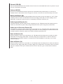
Phantomspeisung-LED (10)
Diese LED leuchtet auf, wenn der Phantomspeisung-Schalter
(11) gedrückt wurde.
Phantomspeisung-Schalter (11)
Versorgt die Eingangs-XLR-Stecker mit 48 V Gleichstrom, um
Mikrofone mit Phantomspeisung zu betreiben.
Wird die Phantomspeisung verwendet, dürfen keine
unsymmetrierten dynamischen Mikrofone oder anderen Geräte
an die XLR-Eingänge angeschlossen werden, die diese
Spannung nicht bearbeiten können. Ist die Phantomspeisung
aktiviert, leuchtet die Phantomspeisung-LED (10) auf.
EFX/Return (12)
Mit dem EFX/Return-Pegelregler wird der Pegel geregelt, der
von den Return-Eingängen (30) an den Left/Right-Main-Bus
gesendet wird.
Tape To CTRL/HP (13)
Mit diesem Schalter wird Tape Return den Control-Room- (32)
und Kopfhörerausgängen (20) zur Überwachung ohne Latenzzeit
zugefügt.
Tape to Mix (14)
Ist dieser Schalter aktiviert, wird das Signal von den Tape-
Eingängen (38) zu den Main-Ausgängen (31) geleitet.
Power LED (15)
Die LED leuchtet auf, wenn das Gerät eingeschaltet ist, mit Wechselstrom versorgt wird und störungsfrei arbeitet.
MON Send Master (16)
Dies ist der Master-Ausgangspegelregler für den Monitor-Mix. Der an die Monitor-Send-Klinke (33) gesendete
Ausgangspegel wird mit den Mon-Send-Reglern des Kanals (5) und diesem Master-Regler eingestellt.
EFX Send Master (17)
Dies ist der Master-Ausgangspegelregler für den EFX-Mix. Der an die EFX-Send-Klinke gesendete Ausgangspegel
wird mit den Kanalpegelreglern (9), den Kanal-EFX-Send-Reglern (6) und diesem Master-Regler eingestellt.
Contour-Schalter (18)
Ist dieser Schalter aktiviert, wird das Signal durch Hinzufügen von Bässen und Höhen verstärkt. Dies ist bei
geringeren Lautstärken für Tonband- bzw. CD-Playback besonders wirksam.
80 Hz Low Cut (19)
Der Tiefpassfilter hat eine Eckfrequenz von 80 Hz. Ist er aktiviert, kann er die Klarheit verstärken, indem er die
tiefen Frequenzen herausnimmt, durch die ein Mix unsauber klingen kann. Diese Funktion ist besonders hilfreich bei
Außenveranstaltungen an einem windigen Tag oder auf einer weiten, lauten Bühne. Diese Umgebungsgeräusche
können die Leistung des Beschallungssystems beeinträchtigen. Mittels dieses Schalters werden diese Frequenzen aus
dem System herausgenommen und die Leistung wieder da eingesetzt, wo sie benötigt wird.
Kopfhörerausgang (20)
Der Kopfhörerausgang ist eine 1/4"-Klinke (Spitze = links, Ring = rechts, Masse = Erde). Das an diesen Ausgang
gesendete Signal ist in der Regel der Left/Right-Mix. Ist der Tape-to-Control-Room-Schalter aktiviert, wird das Tape-
Eingangssignal dem Left/Right-Mix zugefügt und kann über die Kopfhörer überwacht werden.
14
10
11
12
13
14
15
16
17
18
19
20
21
22
23

15
RR ÜÜ CC KK SS EE II TT EE
35
36
37
38
Headphone-Pegel (21)
Mit diesem Regler wird der Ausgangspegel für Kopfhörer und Abhörraum eingestellt. Um Hörschäden zu
vermeiden, muss dieser Regler vollständig im entgegengesetzten Uhrzeigersinn heruntergedreht werden, bevor Sie
Kopfhörer verwenden. Drehen Sie den Knopf langsam im Uhrzeigersinn, bis ein angenehmer Hörpegel erreicht ist.
Das Signal in den Kopfhörern ist in der Regel das Left/Right-Signal. Wird der Tape-to-Control-Room-Schalter (13)
gedrückt‚ wird das Tape-Signal zugefügt.
LED-Messanzeigen (22)
Zwei Sechs-Segment-LED-Anzeigen überwachen die Pegel der Main Left/Right-Ausgänge. Sie sind von -20 dB bis +19
dB geeicht. 0 dB auf der Messanzeige entspricht +4 dBu an den Ausgängen.
Master Level Fader (23)
Der Master-Fader regelt den Pegel, der an die Left- und Right-Hauptausgänge gesendet wird. Die besten Ergebnisse
werden erzielt, wenn dieser Regler um die Position 0 eingestellt wird.
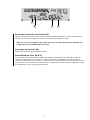
Mic- (XLR-) Eingänge (24)
Symmetrierte XLR-Eingänge, die für ein Mikrofon oder eine andere niederohmige Quelle optimiert wurden. Stift 2
ist der positive Eingang. Auf Grund der Vielzahl an möglichen Gain-Einstellungen können Signalpegel von bis zu +14
dBu erreicht werden.
Line- (1/4"-) Eingänge (25)
Dies ist ein symmetrierter 1/4"-(TRS)-Klinkeneingang mit einer Impedanz von 10 kOhm. Die Spitze ist der positive
Eingang und sollte für unsymmetrierte Eingänge verwendet werden. Sein Gain liegt 20 dB unter dem des XLR-
Eingangs, und er hat keine Phantomspeisung. Die Mic- und Line-Eingänge sollten nicht gleichzeitig verwendet
werden.
Insert (26)
1/4"-Klinkenstecker, der das Einschleifen eines externen Signalprozessors in den Kanalsignalweg ermöglicht. Spitze
= Send, Ring = Return, Masse = Erde.
Stereo- (1/4") Eingänge (27)
Diese unsymmetrierten 1/4"-Eingänge dienen als Stereo-Line-Eingang mit beiden Klinken oder als Mono-Eingang,
wenn der Anschluss nur an den Left/Mono-Eingang erfolgt. Damit diese Klinken aktiv sind, muss der A/B-
Eingangswahlschalter auf „A“ stehen.
RCA-Eingänge (28)
Diese Cinch-Eingänge fungieren als Stereo-Line-Eingänge. Damit diese Klinken aktiv sind, muss der A/B-
Eingangswahlschalter auf „B“ stehen.

16
A/B-Schalter (29)
Der A/B-Eingangswahlschalter erweitert die Fähigkeiten des PV
®
8-Mischpults, da zwei Stereoquellen an jeden
Stereo-Line-Eingang angeschlossen werden können. Anstatt sie nochmals anschließen zu müssen, kann mit dem
Schalter ausgewählt werden, welche Eingangsklinken aktiv sind.connected to each stereo line input. Instead of re-
patching, the switch selects which input jacks are active.
EFX Return (30)
Die EFX-Return-Eingänge (Left/Mono, Right) verfügen über zwei 1/4"-Klinken. Diese Eingänge können mit
symmetrierten Klinkensteckern (Spitze, Ring, Masse) oder unsymmetrierten Klinkensteckern (Spitze, Masse)
verwendet werden. EFX Return wird über den EFX/Return-Pegelregler (19) geregelt.
Left/Right-Ausgänge (31)
Die Left/Right-Ausgänge verfügen über zwei symmetrierte 1/4"-Klinken. Diese Ausgänge können mit symmetrierten
Klinkensteckern (Spitze, Ring, Masse) oder unsymmetrierten Klinkensteckern (Spitze, Masse) verwendet werden.
Control-Room-Ausgänge (32)
Die Control-Room-Ausgänge verfügen über zwei symmetrierte 1/4"-Klinken. Diese Ausgänge können mit
symmetrierten Klinkensteckern (Spitze, Ring, Masse) oder unsymmetrierten Klinkensteckern (Spitze, Masse)
verwendet werden. Der Control-Room-Ausgangspegel wird mit dem Headphone-Pegelregler (21) eingestellt.
MON Send (33)
Der MON Send verfügt über eine symmetrierte 1/4"-Klinke in der Master-Stufe. Dieser Ausgang kann mit
symmetrierten Klinkensteckern (Spitze, Ring, Masse) oder unsymmetrierten Klinkensteckern (Spitze, Masse)
verwendet werden. Der MON-Mix wird durch die Stärke des Signals, das an den MON-Bus in jedem Kanal
gesendet wird, und durch den Monitor-Master-Regler festgelegt.
EFX Send (34)
Der EFX Send verfügt über eine symmetrierte 1/4"-Klinke in der Master-Stufe. Diese Ausgänge können mit
symmetrierten Klinkensteckern (Spitze, Ring, Masse) oder unsymmetrierten Klinkensteckern (Spitze, Masse)
verwendet werden. Der EFX-Mix wird durch die Stärke des Signals, das an den EFX-Bus in jedem Kanal gesendet
wird, und durch den EFX-Master-Regler festgelegt.

17
35
36
37
38
Netzadaptereingang (35)
Zum Anschließen des beiliegenden Netzteils. Das Netzteil muss an den PV
®
8 angeschlossen werden, bevor dieser
an eine Stromquelle angeschlossen wird.. Nur Adapter mit 16 V Wechselstrom, 1 A verwenden.
Hinweis: Nur durch Peavey-Ersatzteil Nr. 70902571 (USA) oder 70902572 (Export) ersetzen.
Power-Schalter (36)
Durch Drücken dieses Schalters wird das Gerät mit Netzstrom versorgt.
Tape In/Out (38 & 37)
An die Tape-Eingangsklinken können die Ausgangspegel von Tonband, CD-Player oder Computer-Soundkarte
angeschlossen werden. Der Ausgangspegel beträgt +4 dBu für den Anschluss an einen Tonband- oder
Soundkarteneingang. Die Tape-Eingänge können als zusätzlicher Stereoeingang verwendet werden, wenn der Tape-
to-Main-Mix-Schalter (14) gedrückt wird. Der Tape-Eingang kann zudem verwendet werden, um den Tonband-
bzw. Soundkartenausgang ohne die Gefahr eines Feedbacks zu überwachen.

18
PV
®
8Console de Mixage Compacte
Description
Félicitations pour l’achat de la Peavey PV8, unité de mixage au format table. La PV8 est idéale pour toutes applications
d’enregistrement ou de diffusion où la compacité du matériel est importante.
Caractéristiques
➡ Quatre entrées XLR Micro
➡ Deux canaux Stéréo avec entrées Jack 1/4" (6.35mm)
➡ Egalisation trois-bandes par canal
➡ Sélecteur A/B d’entrée Stéréo
➡ Insertion d’effets sur chaque canal
➡ LEDs de niveau pour prévenir tout écrêtage du signal
➡ Alimantation Phantom 48V à interrupteur
➡ Envoi vers effet sur chaque canal avec retour d’effets Stéréo
➡ Envoi vers bus de retour de scene sur chaque canal
➡ Possibilité d’enregistrement sans retard (Zero Latency)
➡ Sortie d’écoute additionnelle (Control Room) avec contrôle niveau
➡ Interrupteur de contour (filtre égaliseur en sortie)
➡ filtre coupe_bas 80 Hz à interrupteur
FFRRAANNÇÇAAIISS

Gain (1)
Ce contrôle vous permet d’ajuster la sensibilité d’entrée du canal correspondant, celui-ci pouvant s’accommoder de
la plupart des types de signaux. Pour maximiser la qualité du signal, le niveau de celui-ci dans le canal doit être fait
avec le niveau de sortie ajusté à 0. Si la Led d’écrètage s’illumine de facon prolongée, le gain du signal doit être
réduit.
Hi EQ (2)
Réglage de tonalité actif de type escalier
permettant de modifier les niveaux des hautes
fréquences de +/-15 dB.
Mid EQ (3)
Réglage de tonalité actif de type escalier
permettant de modifier les niveaux des
fréquences médium de +/-15 dB.
Low EQ (4)
Réglage de tonalité actif de type escalier
permettant de modifier les niveaux des basses
fréquences de +/-15 dB.
Attention: Un niveau excessif de basses fréquences augmente considérablement les consommations en puissance et
peut endommager vos hauts-parleurs.
MON Send (5)
Ce contrôle vous permet d’ajuster le niveau du signal envoyé au bus de retour de scène (Monitor). Ce signal n’est
pas affecté par le contrôle de niveau du canal ,mais par ses contrôles d’égalisation.
EFX Send (6)
Ce contrôle vous permet d’ajuster le niveau du signal envoyé au bus d’effet. Le niveau de ce signal est également
affecté par le contrôle de niveau du canal.
Pan (7)
Détermine la position du canal dans l’image stéréo. En augmentant ce contrôle, vers la gauche (sens contre-
horaire), le signal diminuera dans le champ droit tout en augmentant dans le champ gauche et vice-versa. Sur les
canaux Stéréo (5/6 et 7/8), ils permettent d’ajuster les niveaux relatifs des signaux Droite et Gauche.
Clip LED (8)
(Leds d’indication de seuil d’écrètage) Ces Leds vous indiquent lorsque le niveau du signal est proche de la
sensibilité maximale. Le circuit de détection analyse le signal à toutes les étapes du routage de clui-ci et la LED
s’illuminera pour indiquer un niveau de +19dBu, prévenant que les contrôles de gain ou d’égalisation doivent être
atténués. Ce seuil est environ 3dB avant écrètage.
Level (9)
Ce contrôle vous permet d’ajuster le niveau du signal de sortie. Le niveau d’utilisation commun (gain unitaire) est en
position 0.
19
PP AA NN NN EE AA UU AA VV AA NN TT
1
2
3
5
6
8
9
4
7

Phantom Power LED (10)
Cette LED s’illumine pour vous indiquer que l’alimentation
Phantom est active.
Phantom Power Switch (11)
Cet interrupteur vous permet d’activer ou de désactiver
l’alimentation Phantom de votre unité. Celle-ci se traduit par
une tension de 48V appliquées aux entrées XLR.
Si l’alimentation est active, assurez-vous de ne pas connecter
aux connecteurs XLR des micros ou autres unités de signal qui
ne suppoteraient pas ce voltage. La Led témoin
correspondante (10) vous indique le status de l’alimentation
Phantom.
EFX/Return (12)
Ce contrôle vous permet d’ajuster le niveau du signal des
entrées ‘EFX Return’ (30) dans les bus principaux
Droite/Gauche.
Tape To CTRL/HP (13)
En activant cet interrupteur vous ajoutez le signal présent aux
entrées ‘Tape Return’ au signal d’écoute (Control Room - 32) et
casque (20).
Tape to Mix (14)
En activant cet interrupteur vous ajoutez le signal présent aux entrées ‘Tape Return’ au signal des sorties
principales (31).
Power LED (15)
Cette LED vous indique si votre unité est sous tension.
MON Send Master (16)
Ce contrôle vous permet d’ajuster le niveau général du signal envoyé à la sortie ‘MON Send’ (33).
EFX Send Master (17)
Ce contrôle vous permet d’ajuster le niveau général du signal envoyé à la sortie ‘EFX Send’ (34).
Contour Switch (18)
Cet interrupteur vous permet d’appliquer une égalisation pré-définie ajoutant à la fois des hautes et basses
fréquences pour une accentuation du relief sonore. Ce sélecteur est particulièrement efficace pour des
applications musicales à faible niveau.
80 Hz Low Cut (19)
Ce filtre coupe-bas 80Hz vous permet d’éliminer les basses fréquences de votre signal pour lui ajouter de la
clarté, particulièrement efficace lorsque l’amplification des basses fréquences gaspille la puissance nécessaire.
Headphone Output (20)
La sortie du bus d’effet est un Jack 1/4" symétrique (TRS, pointe = gauche; anneau = droit; corps = masse).
Généralement, le signal d’écoute correspond au sorties principales; si le sélecteur ‘Tape to Control Room’(13)
est engagé, le signal pré-enregistré (Tape) est ajouté au signal d’écoute.
20
10
11
12
13
14
15
16
17
18
19
20
21
22
23
Seite laden ...
Seite laden ...
Seite laden ...
Seite laden ...
Seite laden ...
Seite laden ...
Seite laden ...
Seite laden ...
Seite laden ...
Seite laden ...
Seite laden ...
Seite laden ...
Seite laden ...
Seite laden ...
Seite laden ...
Seite laden ...
-
 1
1
-
 2
2
-
 3
3
-
 4
4
-
 5
5
-
 6
6
-
 7
7
-
 8
8
-
 9
9
-
 10
10
-
 11
11
-
 12
12
-
 13
13
-
 14
14
-
 15
15
-
 16
16
-
 17
17
-
 18
18
-
 19
19
-
 20
20
-
 21
21
-
 22
22
-
 23
23
-
 24
24
-
 25
25
-
 26
26
-
 27
27
-
 28
28
-
 29
29
-
 30
30
-
 31
31
-
 32
32
-
 33
33
-
 34
34
-
 35
35
-
 36
36


Peavey PV 8 Benutzerhandbuch
- Kategorie
- Zusätzliche Musikausrüstung
- Typ
- Benutzerhandbuch
- Dieses Handbuch ist auch geeignet für
in anderen Sprachen
- English: Peavey PV 8 User manual
- français: Peavey PV 8 Manuel utilisateur
Verwandte Papiere
-
Peavey PV 6 Compact Mixer Benutzerhandbuch
-
Peavey PV 10 Benutzerhandbuch
-
-
-
Peavey 16FX Bedienungsanleitung
-
-
-
-
-
