88
Setting up your C30 pre-amplier
LEFT RIGHT
–dB +dB
–dB +dB
‘Switch on’
state
–dB +dB
Volume Resolution – Standard,
fine or Reference. ‘Standard’ and
‘Fine’ represent different levels of volume
control sensitivity. The ‘Reference’ setting
gives absolute increments in 0.5dB steps.
Volume display mode – graphic
or numeric shows the volume either
as a bar graph or as a number. If Volume
resolution is set to ‘Reference’ a numeric
volume display shows the actual decibel
figure.
Input Trims – use the source select
buttons and Control knob to set input
trims for each source. Input trims are used
to compensate for variations in output
levels of different source equipment.
Max. ‘On’ Volume – This can be used to
limit the maximum volume the amplifier
operates at when it is first switched on.
The system comes on at this volume if
the last used volume exceeds this value.
If this is set to ‘Disabled’, the amplifier
comes on at the last used volume.
Tone Control – Global or Per
source. This specifies the scope of
changes for ‘Bass’ and ‘Treble’ tone settings.
The default setting is ‘Global’ which affects
all inputs equally. ‘Per source’ allows you
to set tone controls for individual inputs:
once set, the amplifier remembers tone
settings for each input.
Processor Mode – This mode enables
you to adjust the gain of the amplifier. The
amplifier can then be used to drive the
front left and right speakers in a surround
sound system when fed from a separate
processor. The volume of the entire
system can then be controlled using
the processor. Feed the sound from the
processor into the TAPE input. Set the
gain to match the amplifiers that drive
your other loudspeakers.
Welcome message – You can change
the power on ‘Welcome message’ from
‘Arcam Amp’ to display your name,
postcode, etc. When customising the
message, use the UP and DOWN buttons
to select the cursor position and the
Control knob to change the letter.
Phono/Aux Text – The C30 is fitted
with a phono module, so when the
phono input is selected as the source,
‘PHONO’ is displayed. Should you wish to
remove the phono board, then the AUX
connections can be used as a line input.
In this case, change the text displayed to
‘AUX’, using this menu option.
Restore Settings – this restores all
amplifier settings, including input trims
and the welcome message, to their
factory defaults.
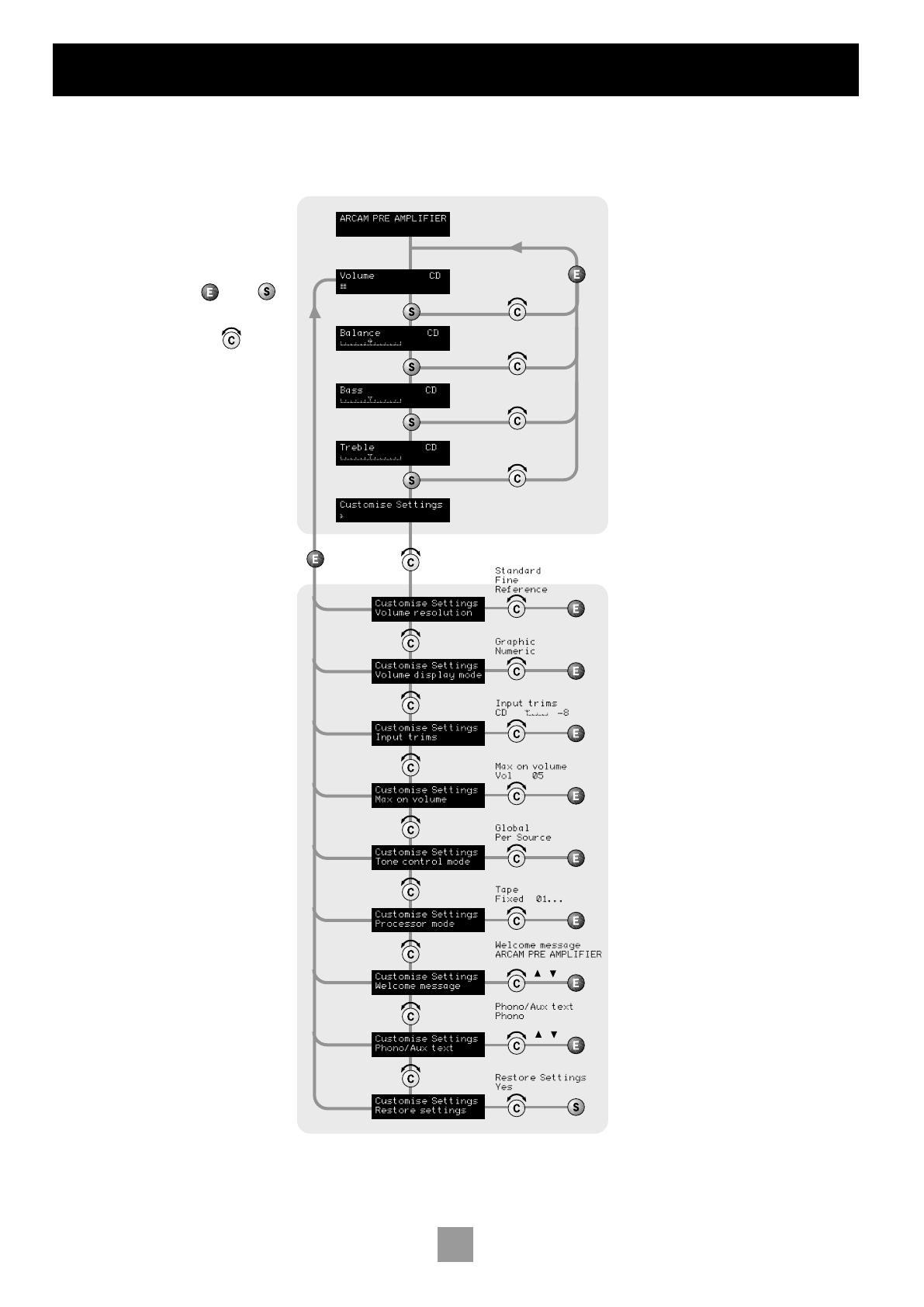
INTRODUCTION
The C30 allows you to adjust listening
settings to suit your taste, and to
customize various features of the
amplifier to fit your system. Use this
diagram to help you navigate through the
settings available.
The ENTER and SELECT buttons from
the front panel are represented in the
diagram by the symbols and
respectively.
The Control knob is shown as .
ADJUSTING LISTENING
SETTINGS
The default display mode is VOLUME,
where the Control knob is used to adjust
the sound level.
Press SELECT once to enter edit mode,
then repeatedly to cycle through the
other sound settings: BALANCE, BASS
and TREBLE. When a setting is selected
(shown on the display), it can be adjusted
by using the control knob. Press ENTER
to store the change you have made and
return to default (volume) mode, or press
SELECT again to move to the next setting.
CUSTOMISING AMPLIFIER
SETTINGS
It is possible to customise (change to your
preference) many of the features of the
C30. To do this, proceed as follows:
1. Press SELECT repeatedly until the
display shows ‘CUSTOMISE->’;
2. Rotate the Control knob to
choose which setting you wish to
alter;
3. Press SELECT to adjust the chosen
setting with the Control knob;
4. Press ENTER to confirm the
adjustment, or press SELECT to
confirm the adjustment and move
on to the next item.
Press ENTER twice to leave the Customise
menu.


