
DH-SMT/DK VI.KN.Z2.7S © Danfoss 10/2006 1
087R9768
087R9768
*087R9768*
*VIKNZ27S*
Instructions
ECA 71 mounting guide
ENGLISH
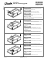
1. Dismount cover plate B on the rear side of the ECL Comfort
controller by using a small wire cutter.
DEUTSCH
1. Entfernen Sie mit der Hilfe einer Zange die Abdeck-
platte B von der Unterseite des ECL Comfort Reglers.
POLSKI
1. Zdemontuj (wytnij) zaślepkę B na tylnej ściance ECL Comfort
przy użyciu niewielkich cążek.
РУССКИЙ
1. Демонтируйте вставку на задней стороне контроллера ECL
Comfort с помощью бокорезов.
ENGLISH
2. Insert the MODBUS module into the slides and press it gently
into the connector on the ECL Comfort CPU board.
DEUTSCH
2. Schieben Sie das MODBUS-Modul in die Führung und drücken
Sie es behutsam in das Anschlusssockel des ECL Comfort
Prozessors.
POLSKI
2. Delikatnie wsuń płytkę modułu MODBUS w slot na płycie
CPU ECL Comfort i dociśnij w celu zapewnienia właściwego
połączenia.
РУССКИЙ
2. Установите модуль MODBUS в направляющие и мягким
нажимом соедините с разъемом платы контроллера.
ENGLISH
3. Mount the new cover plate B which is delivered with the
module.
DEUTSCH
3. Befestigen Sie die neue Abdeckplatte B, die dem Modul
beigelegt ist.
POLSKI
3. Zamontuj nową zaślepkę otworu B dostarczoną w komplecie.
РУССКИЙ
3. Смонтируйте новую вставку из комплекта поставки.
ENGLISH
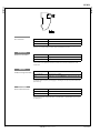
4. The connector must be inserted into the ECL Comfort as shown
here.
DEUTSCH
4. Der Anschlussstecker muss wie hier gezeigt eingesteckt
werden.
POLSKI
4. Złącze elektryczne podłącz do ECL Comfort jak pokazano na
rysunku.
РУССКИЙ
4. Установите внешний разъем согласно схеме.

087R9768
087R9768
2 VI.KN.Z2.7S © Danfoss 10/2006 DH-SMT/DK
ECA 71
ENGLISH
Pin connection
Pin 1 Network connection MODBUS B / DATA + / D1
Pin 2 (middle) Common / SGND
Pin 3 Network connection MODBUS A / DATA - / D0
2 poles + common are galvanically isolated. The pins are not interchangeable.
There are no pull up / down resistors and no termination resistor.
DEUTSCH
Elektrische Anschlüsse
Pin 1 Netzwerkanschluss MODBUS B / DATA + / D1
Pin 2 (mittlere) Abgeschirmt / SGND
Pin 3 Netzwerkanschluss MODBUS A / DATA - / D0
Zwei Pole + Abschirmung sind galvanisch getrennt. Die Pins sind gegenseitig nicht
vertauschbar. Pull-Up Widerstände und Terminationswiderstand werden nicht
verwendet.
POLSKI
Podłączenia wyprowadzeń
Pin 1 Podłączenie sieciowe MODBUS B / dane wejściowe / D1
Pin 2 (środkowy) Wspólny (masa) / SGND
Pin 3 Podłączenie sieciowe MODBUS A / dane wyjściowe / D0
Oba bieguny i ekran są izolowane galwanicznie. Piny nie są zamienne. Nie są
potrzebne żadne rezystory podciągające/ obniżające ani rezystory zakończeniowe
(terminatory).
РУССКИЙ
Назначение контактов
Контакт 1 Сетевое соединение MODBUS B / DATA+ / D1
Контакт 2 (средний) Общий / SGND
Контакт 3 Сетевое соединение MODBUS A / DATA - / D0
Два полярных провода, плюс экран с гальванической изоляцией. Контакты не
взаимозаменяемы. Подтягивающие, заземляющие и терминальные резисторы
не требуются.
-
 1
1
-
 2
2


in anderen Sprachen
- English: Danfoss ECA 71 Installation guide
- polski: Danfoss ECA 71 Instrukcja instalacji
Verwandte Artikel
-
Danfoss ECA 71 Installationsanleitung
-
-
-
-
-
-
-
-