MULTIPLEX Contestbericht Stoerklappe Bedienungsanleitung
- Typ
- Bedienungsanleitung

Contest-Störklappe
Contest-StörklappeBest.-Nr. 72 2645
Breite 250 mm, Einbauhöhe 16 mm
für Modelle von ca. 2,60 bis ca. 3,60 m
Contest Störklappe Best.-Nr. 72 2646
Breite 370 mm, Einbauhöhe 16 mm
für Modelle von ca. 3,20 bis
ca. 4,60 m
Herkömmliche Stör-
klappen haben, insbesondere
in langer Ausführung, den Mangel, daß sie
oft nicht sicher öffnen oder schließen oder bei hohen Flug-
geschwindigkeiten wegen der asymmetrischen Zuhaltung
"aufgesaugt" werden. Durch die Zentralverriegelung* der
MULTIPLEX Contest-Störklappe sind die Probleme hun-
dertprozentig gelöst. Die außen aufliegenden Klappen-
lamellen werden in der Mitte verriegelt und überspannt,
so ist die Klappe sauber eingefahren und kann auch im
Schnellflug nicht "aufgesaugt" werden.
- Verriegelung aus der Mitte* - die Klappe schließt sicher.
- In eingebautem Zustand voll demontierbar.
- Anlenkung von innen - besonders vorteilhaft, wenn die
Störklappe unter der Beplankung eingebaut wird.
- Wenn nötig, kann auf seitlichen Antrieb umgebaut wer-
den.
- Alle Teile in eingebautem Zustand austauschbar
* nur in der 370mm Version
Bitte beachten Sie:
Bei fertig montierten und geschlossenen Störklappen
kann es vorkommen, daß sich diese von außen nicht
öffnen lassen, weil die Verriegelung eingerastet ist.
Auf keinen Fall die Lamellen mit Gewalt öffnen, da
diese sonst beschädigt werden.
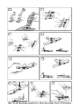
Zum Öffnen der Störklappen klopfen Sie diese einige Male
wie in Abb.1 gezeigt auf eine feste Unterlage, damit sich
die Verriegelung löst. Anschließend können die Lamellen
vorsichtig und leichtgängig aus dem Klappenkasten her-
ausgehoben werden.
Demontage von montierten Störklappen
Die Störklappenlamellen und die zugehörigen Hebel sowie
der Anlenkhebel können vom Klappenkasten abmontiert
werden. Dies ist einerseits beim Einbau des Klappen-
kastens unter die Beplankung des Flügels notwendig und
andererseits beim Austausch von defekten Teilen von
Vorteil.
1. Die obere Lamelle wird bei geöffneter Klappe nach
oben abgezogen.
2. Die untere Lamelle wird durch Drücken mit dem Finger
nagel auf den Haltepunkt und gleichzeitigem Gegenhalten
gelöst und abgenommen.
Abb. 2
Abb. 3
3.Die Hebel können nun mit
Hilfe einer Zange und seitlichem Druck
sowie gleichzeitigem, vorsichtigem Drehen aus
der Lagerachse ausgerastet werden.
Bei der linken Klappe kann der Hebel mit der Anlenk-
mechanik nur aus dem Führungsklötzchen gezogen wer-
den, wenn der Kunststoffhebel nach dem Ausrasten aus
der Lagerachse wieder waagerecht gelegt wird.
Bei der rechten Klappe ist die Hebelstellung unproblema-
tisch.
Zusammenbau unmontierter Störklappen
1. Bei der linken Klappe kann der Hebel mit der Anlenk-
mechanik nur in das Führungsklötzchen eingeschoben
werden, wenn der Kunststoffhebel waagerecht gelegt
wird. Lagerauge des Kunststoffhebels auf der Lagerachse
positionieren und z.B. mit einem Schraubendreher, durch
Druck von oben, einrasten.
Bei der rechten Klappe ist die Hebelstellung unproblema-
tisch. Hebel mit der Anlenkmechanik in das Führungs-
klötzchen einschieben und das Lagerauge des senkrecht
gestellten Kunststoffhebels in die Lagerachse einrasten.
Dazu den Hebel mit einer Zange packen.
2. Die untere Lamelle bei aufgestellten Hebeln
auf die Haltenocken aufdrücken. Dabei muß die Einlauf-
schräge am Lamellenende zur Anlenkseite zeigen.
3. Die obere Lamelle bei aufgestellten Hebeln
auf den Lagerpunkten positionieren und von Hand auf-
drücken. Dabei muß die Einlaufschräge am Lamellenende
ebenfalls zur Anlenkseite zeigen.
4. Störklappe auf Funktion und Leichtgängigkeit überprü-
fen.
Anlenkung von Contest-Störklappen
Die Anlenkung von Contest-Störklappen erfolgt innerhalb
des Klappenkastens. Nach dem Abnehmen der Lamellen
ist das Anlenkgestänge problemlos zugängig.
Löten Sie auf einen Stahldraht mit 1,3mm eine Löthülse
und schrauben einen Gabelkopf auf. Verlegen Sie im
Flügel eine Bowdenzugaußenhülle von der Störklappe
zum Servoabtrieb. Die Bowdenzugaußenhülle in die seit-
liche Bohrung des Klappenkastens stecken und mit einem
Tropfen Sekundenkleber sichern. Gestänge einbauen und
den Gabelkopf am Betätigungshebel im Klappenkasten
einhängen. Gestänge servoseitig anschließen, Lamellen
montieren und auf einwandfreie Funktion überprüfen.
Abb. 5
Abb. 6
Abb. 4
Abb. 7
Abb. 8
Abb. 9
Abb. 1

Aérofreins Contest Réf. Cde 72 2645
Largeur 250 mm, hauteur de montage 16 mm, pour
modèles de 2,60 à 3,60 m environ.
Aérofreins Contest Réf. Cde 72 2646
Largeur 370 mm, hauteur de montage 16 mm, pour
modèles de 3,20 à 4,60 m environ.
Les aérofreins courants, et plus particulièrement lorsqu’ils
sont larges, présentent le défaut de ne pas sortir ou rentrer
correctement, ou, du fait de leurs configurations
asymétriques, sont «aspirés» à grande vitesse. Grâce au
verrouillage centralisé des aérofreins Contest
MULTIPLEX, ces problèmes sont résolus à 100 %. La
lame supérieure de l’aérofrein est verrouillée en son milieu,
et recouverte, ainsi l’aérofrein est rentré correctement, et
ne peut être «aspiré» à grande vitesse.
- Verrouillage au milieu l’aérofrein rentre correctement
- entièrement démontable une fois monté
- commande de l’intérieur - particulièrement avantageux
si l’aérofrein est monté sous le coffrage.
- si nécessaire, peut être modifié pour obtenir une
commande latérale.
- une fois monté, toutes les pièces peuvent être
remplacées.
Attention : il se peut que les aérofreins, une fois
montés, ne puissent pas être sortis à partir de
l’extérieur parce que le verrou est bloqué. Ne forcez
en aucun cas, vous pourriez endommager les lames.
Pour sortir les aérofreins, donnez de petits coups comme
vous le montre la vue 1, aile calée, pour que le verrou se
débloque. Par la suite, les lames peuvent être retirées
avec précaution du boîtier des aérofreins.
Démontage des aérofreins assemblés
Les lames et les renvois correspondants ainsi que la tringle
de commande peuvent être démontés du boîtier. D’une
part, ceci est nécessaire en cas de montage du boîtier
d’aérofreins sous le coffrage et d’autre part, avantageux
en cas de remplacement de pièces défectueuses.
1. La lame supérieure est retirée par le haut, aérofrein
sorti.
2. La lame inférieure est débloquée et retirée en appuyant
avec l’ongle sur le point de fixation en évitant la
déformation de cette dernière en la soutenant.
3. Les renvois peuvent être retirés de leur ajustement avec
une pince en exerçant une légère rotation et pression
latérale.
Aérofreins Contest
Vue. 2
Vue. 3
Vue. 1
Vue. 5
Vue. 4
Vue. 6
Vue. 7
Vue. 8
Vue. 9
Sur l’aérofrein gauche, le renvoi et la tringle de commande
ne peuvent être retiré du bloc de guidage que si le renvoi
plastique est en position horizontale après démontage de
ce dernier.
Pour l’aérofrein droit, la position du renvoi ne pose aucun
problème
Assemblage des aérofreins non-montés
1. Sur l’aérofrein gauche, le renvoi et la tringle de
commande ne peuvent être inséré dans le bloc de guidage
que si le renvoi plastique est en position horizontale
Positionnez le renvoi par rapport à son axe de rotation, et
mettez-le en place, à l’aide d’un tournevis par exemple,
en appuyant sur le dessus.
Pour l’aérofrein droit, la position du renvoi importe peu.
Engagez le renvoi avec la tringle de commande dans le
bloc de guidage, et montez le renvoi plastique en position
verticale sur son axe de rotation. Pour cela, tenez le renvoi
avec une pince.
2. Montez la lame inférieure sur ses points de fixations
en appuyant dessus, renvoi monté. Le côté biaisé de
l’extrémité de la lame doit être du côté de la tringle de
commande.
3. Positionnez la lame supérieure sur ses axes
d’articulation, renvoi monté, puis montez-les
manuellement. Le côté de l’extrémité de la lame doit
également être du côté de la tringle de commande.
4. Vérifiez le bon fonctionnement de l’aérofrein.
Commande des aérofreins Contest
La commande des aérofreins Contest se fait à l’intérieur
du boîtier. Après avoir retiré les lames, l’accès à la tringle
de commande ne pose plus aucun problème.
Soudez un embout sur une corde à piano de 1,3 mm et
vissez-y une chape. Posez une gaine de commande dans
l’aile qui va du servo à l’aérofrein. Engagez la gaine dans
le perçage latéral du boîtier de l’aérofrein, et fixez-la avec
une goutte de colle cyano. Montez la tringle, et fixez la
chape sur le renvoi de commande dans le boîtier. Ajustez
la tringle côté servo, montez les lames et vérifiez le bon
fonctionnement de l’ensemble.

Contest airbrake, Order No. 72 2645
Length 250 mm, installed height 16 mm
For models of about 2.60 to 3.60 m wingspan
Contest airbrake, Order No. 72 2646
Length 370 mm, installed height 16 mm
For models of about 3.20 to 4.60 m wingspan
There are often problems with conventional airbrakes -
especially the longer versions. They tend not to open or
close reliably, or get „sucked out“ at high airspeeds
because they are only latched at one end. The central
locking system * of MULTIPLEX Contest airbrakes solves
these problems one hundred percent. The outer brake
blades feature a central latch and an over-centre lock, so
the brake retracts smoothly every time and cannot be
sucked out at high speed.
- Central locking - the airbrake closes reliably.
- Can be dismantled completely even when installed.
- Internal actuation - very helpful if the airbrake is to be
installed under the wing skin.
- If necessary the unit can be converted to side actuation.
- All parts can be removed and replaced even when the
brake is installed.
* 370 mm version only
Please note:
When the airbrake is assembled and closed you may
find that you cannot open it from outside because
the latch has engaged. If this should happen on no
account force the blades open as this will inevitably
damage them.
Just tap the airbrake a few times on a firm surface as
shown in Fig. 1, and this will disengage the latch. You will
now find that the brake blades can be lifted out of the box
easily if you work carefully.
Dismantling assembled airbrake units
The airbrake blades, levers and actuating arm can all be
removed from the airbrake box. This is often necessary if
you are installing the brake box under the wing skin, and
it is also useful when you want to replace damaged or
worn parts.
1. When the airbrake is extended the top blade can be
lifted off upwards.
2. The bottom blade can be disengaged by pressing on
its retaining point with a fingernail and pushing in the
opposite direction. It can then be removed.
3. The levers can now be disengaged from their pivot
shafts by gripping them with a pair of pliers and carefully
twisting them off sideways.
[
Contest airbrakes
Fig. 1
Fig. 2
Fig. 3
The lever and actuating mechanism of the left-hand
airbrake can only be removed from the guide block if the
plastic lever is laid horizontal after disengaging it from
the pivot shaft.
This does not apply to the right-hand airbrake - the lever
can be in any position.
Assembling the airbrake units
1. Left-hand airbrake unit: the lever and actuating
mechanism can only be slid into the guide block if the
plastic lever is held horizontal. Position the hole in the
plastic lever over the pivot shaft and press down from
above using a screwdriver or similar tool to engage it.
Right-hand airbrake unit: the lever can be in any position.
Slide the lever and actuating mechanism into the guide
block and hold the plastic lever vertical. Hold the lever in
a pair of pliers and fit the hole in the lever on the pivot
shaft.
2. Hold the levers erect and press the bottom blade onto
the retaining lugs. The angled end of the blade must face
the end of the box with the actuator.
3. Hold the levers erect, position the top blade on the
pivot points and press down with your fingers. The angled
end of the blade must again face the end of the box with
the actuator.
4. Check that the airbrake works smoothly and freely.
Completing the linkage to the Contest airbrakes
The linkage to the Contest airbrake is connected inside
the airbrake box. Once the blades are removed the
pushrod is freely accessible.
Solder a threaded coupler onto one end of a 1.3 mm Ø
steel pushrod and screw a clevis on the coupler. Install a
bowden cable outer in the wing running from the airbrake
to the servo output arm. Push the end of the bowden cable
outer into the hole in the end of the airbrake box and secure
it with a drop of cyano. Install the pushrod and connect
the clevis to the actuating lever inside the airbrake box.
Connect the pushrod at the servo end, fit the airbrake
blades and check that the system works correctly.
Fig. 4
Fig. 5
Fig. 6
Fig. 7
Fig. 8
Fig. 9

1.
2.
3.
4.
5.
6.
7. 8. 9.
MULTIPLEX Modellsport GmbH & Co. KG ll Neuer Weg 15 ll D-75223 Niefern
-
 1
1
-
 2
2
-
 3
3
-
 4
4


MULTIPLEX Contestbericht Stoerklappe Bedienungsanleitung
- Typ
- Bedienungsanleitung
in anderen Sprachen
Verwandte Artikel
-
MULTIPLEX 21 4164 Bedienungsanleitung
-
-
-
-
-
-
-
-