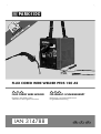
Parkside PFDS 120 A2 Translation Of The Original Instructions
- Typ
- Translation Of The Original Instructions

IAN 314788
FÜLLDRAHT - SCHWEISSGERÄT
Bedienungs- und Sicherheitshinweise
Originalbetriebsanleitung
DE
AT CH
FLUX CORED WIRE WELDER PFDS 120 A2
NI
IE
GB
FLUX CORED WIRE WELDER
Operation and Safety Notes
Translation of the original instructions
GB
IE NI

GB
IE
NI
Before reading, unfold the page containing the illustrations and familiarise yourself with all
functions of the device.
DE
AT
CH
Klappen Sie vor dem Lesen die beiden Seiten mit den Abbildungen aus und machen Sie sich
anschließend mit allen Funktionen des Gerätes vertraut.
GB / IE / NI Operation and Safety Notes Page 5
DE / AT / CH Montage-, Bedienungs- und Sicherheitshinweise Seite 25

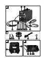
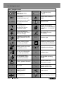
1 2
49101112 357 68
A
B
C D
13 1514 16 17 18
22 23 24 25
19
20
21

E
K
H
N
Q R
F
L
I
O
G
M
J
P
28
28
27
26
19
30
30
29
27
28
19
27
30 33 11
11
32
29
9
31
15
15
9 33
31
19

5
GB/IE/NI
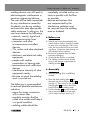
List of pictograms used ................................................................................. Page 6
Introduction ........................................................................................................Page 7
Intended use ............................................................................................................Page 7
Parts description ....................................................................................................... Page 7
Technical specifications .............................................................................................Page 8
Package contents ......................................................................................................Page 8
Safety instructions ...........................................................................................Page 8
Potential hazards during electric arc welding ...............................................................Page 10
Safety information specific to the welding mask ............................................................Page 13
Confined and moist spaces ........................................................................................ Page 13
Protective clothing .....................................................................................................Page 14
Protection against radiation and burns ........................................................................Page 14
EMC device classification ..........................................................................................Page 14
Before use ...........................................................................................................Page 15
Assembly .............................................................................................................Page 15
Assembling the welding mask ....................................................................................Page 15
Inserting the flux-cored wire .......................................................................................Page 16
Using the device ............................................................................................... Page 17
Switching the device on and off .................................................................................Page 17
Setting the welding current .........................................................................................Page 17
Setting the wire feed .................................................................................................Page 17
Welding ..................................................................................................................Page 18
Create a weld seam ..................................................................................................Page 19
Maintenance and cleaning ..........................................................................Page 21
Information about recycling and disposal ..........................................Page 21
Warranty and service information .........................................................Page 21
Warranty conditions .................................................................................................Page 21
Extent of warranty ....................................................................................................Page 21
Processing of warranty claims ....................................................................................Page 22
Service ..................................................................................................................Page 22
EC Declaration of Conformity .....................................................................Page 22
Table of contents

6
GB/IE/NI
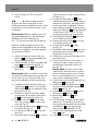
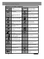
List of pictograms used
Caution!
Read the operating
instructions!
Risk of serious injury
or death!
Power input;
Number of phases and
Caution! Risk of electric
shock!
1 ~ 50 Hz
Alternating current symbol
and rated value of the
frequency
Important note!
Do not dispose of
any electrical devices
in domestic waste!
Dispose of packaging
properly. Do not dispose of
the appliance in household
waste!
Do not use the device
outdoors and never use it
when it is raining!
Self-shielded flux-core
arc welding
An electric shock from the
welding electrode can be
fatal
IP21S Protection type
Inhaling welding smoke
can harm your health.
S
Suitable for welding under
increased electrical hazard
Welding sparks can cause
an explosion or fire.
Single-phase transformer
Arc rays can damage the
eyes and injure the skin.
H Insulation class
Electromagnetic fields
can disrupt the function
of cardiac pacemakers
U
2
Standardised operating
voltage
Caution, potential hazards! I
1max
Greatest rated value
of the mains current
X % Duty cycle I
1eff
Effective value of the
greatest mains current
I
2
Rated value of the
welding current
Earth terminal
Wire feed drive Made of recycling material
List of pictograms used

7
GB/IE/NI
Flux cored wire welder
PFDS 120 A2
z Introduction
Congratulations!
You have purchased
one of our high-quality
devices. Please familiarise yourself with the
product before setup or first use. To do so,
please read through the following operating
and safety instructions carefully. This tool
must be set up or used only by people who
have been trained to do so.
KEEP OUT OF THE REACH
OF CHILDREN!
z Intended use
The device is suitable for self-shielded
flux-core welding using an appropriate wire.
No additional gas is required. The protective
gas is contained in powder form in the wire
itself, thus it is fed directly into the arc.
This means the device is not susceptible to
wind and can be used outside. Only suitable
wire electrodes may be used for the device.
Intended use also involves compliance
with the safety instructions and assembly
instructions and the operating notes in the
operating instructions.
The applicable accident prevention
provisions must be strictly observed.
The device must not be used:
– in rooms with insufficient ventilation,
– in damp or wet environments,
– in explosive atmospheres,
– for the purpose of thawing pipes,
– in the vicinity of people with cardiac
pacemakers and
– in the vicinity of easily inflammable
materials. Use the product only as
described and only for the specific appli-
cations as stated. Keep these instructions
in a safe place. Ensure you hand over all
documentation when passing the product
on to anyone else. Any use that differs
to the intended use as stated above is
prohibited and potentially dangerous.
Damage or injury caused by misuse or
disregarding the above warning is not
covered by the warranty or any liability
on the part of the manufacturer.
Residual risk
Even if you operate the device as intended,
there will be residual risks. The following risk
can occur in the context of the design and
construction of this flux-core welding device:
– eye injuries caused by glare,
– touching hot parts of the device or the
workpiece (burn injuries),
– in the case of insufficient protection, risk of
accidents and burns due to flying sparks
or slag,
– harmful emissions of smoke and gases
caused by lack of air or insufficient
extraction in closed rooms.
Reduce the residual risk by carefully using
the device as intended and observing all
instruction.
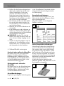
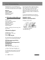
z Parts description
1
Cover wire feed unit
2
Carrying strap
3
Mains plug
4
Earth cable with earth terminal
5
Main switch ON/OFF
(incl. power indicator lamp)
6
Overload protection control lamp
7
Rotaryswitch for welding current setting
8
Setting wheel for wire feed
9
Torch nozzle
10
Torch
11
Torch button
12
Cable assembly with direct connection
13
Welding nozzle (0.6 mm)
14
Welding nozzle (0.8 mm)
Introduction

8
GB/IE/NI
15
Welding nozzle (0.9 mm)
16
Welding nozzle (1.0 mm)
17
Flux-core wire spool (wire reel)
Ø 0.9 mm / 450 g
18
Chipping hammer with wire brush
19
Feed rol
20
Shield body
21
Dark welding lens
22
Handle
23
Welding helmet after assembly
24
Mounting clip
25
Protective glass catch
26
Storage compartment for welding nozzles
27
Setting screw
28
Thrust roller unit
29
Roller holder
30
Feed roll holder
31
Wire outlet
32
Cable assembly bracket
33
Torch neck
z Technical specifications
Mains connection: 230 V~ / 50 Hz
(alternating
current)
Welding current I
2
: 25–120 A
Duty cycle X: 10 % at 120 A
welding current,
60 % at 49 A
welding current
Open circuit voltage U
0
: 31 V
Greatest rated value
of the mains current: I
1max.
17.5 A
Effective value of the
greatest rated current: I
1eff
5.9 A
Welding wire reel max.:
approx. 1000 g
Welding wire diameter
max.: 1.0 mm
Fuse: 16 A
Weight: 13.50 kg
Technical and visual changes can be carried
out over the course of the further develop-
ment without warning. Therefore, all the
dimensions, notices and specifications of
these operating instructions are not guaran-
teed. Thus, legal clams made as a result of
the operating instructions cannot be claimed.
z Package contents
1 flux cored wire welder PFDS 120 A2
1 torch nozzle (pre-assembled)
4 welding nozzles
(1x 0.9 mm pre-assembled; 1x 0.8 mm;
1x 0.6 mm; 1x 1.0 mm)
1 chipping hammer with wire brush
1 flux-core wire Ø 0.9 mm / 450 g
1 welding helmet
1 carrying strap
1 set of operating instructions
Safety instructions
Please read the operating
instructions with care and observe
the notes described. Familiarise
yourself with the device, its
proper use and the safety notes
based on these operating instruc-
tions. The rating plate contains
all technical data of this welding
device; please learn about the
technical features of this device.
This device may be used by
children aged 16 years and
older, and by persons with
reduced physical, sensory or
mental capacities, or a lack of
experience and knowledge,
if they are supervised or have
Introduction / Safety instructions

9
GB/IE/NI
been instructed in how to use
the device safely and under-
stand the dangers that may
arise when using it. Do not
allow children to play with the
device. Cleaning and
day-to-day maintenance must
not be performed by children
without supervision.
Only allow qualified electricians
to carry out repairs and/or
maintenance work.
Only use the welding cables
(PFDS 120 A2 H01N2-
D1x10 mm²) included in the
scope of delivery.
During operation, the device
should not be right against
the wall, covered or wedged
between other devices so that
sufficient air can always be
absorbed from the ventilation
slots. Please ensure that the
device is correctly connected
to the mains voltage. Avoid
any tensile strength on the
power cable. Pull the mains
plug out of the socket prior
to setting the device up in
another location.
If the device is not in opera-
tion, always switch it off using
the ON/OFF switch. Place the
electrode holders on an insu-
lated surface and only remove
the electrodes from the hold-
er after 15 minutes of cooling
down.
Pay attention to the condition of
the welding cable, electrode
holder and the earth terminal.
Wear and tear of the insulation
and the live parts can lead to
hazards and reduce the quality
of the welding work.
Arc welding creates sparks,
molten metal parts and
smoke. Therefore ensure that:
All flammable substances
and/or materials are removed
from the work station and its
immediate surrounding.
Ensure the work station is
ventilated.
Do not weld on containers,
vessels or tubes that contain or
contained flammable liquids or
gases.
Avoid any
form of direct contact with the
welding current circuit. The
open circuit voltage between
the electrode holder and earth
terminal can be dangerous,
there is a risk of electric shock.
Do not store or use the device
in a damp or wet environment
or in the rain. Protection
rating IP21S is applicable in
this case.
Safety instructions

10
GB/IE/NI
Protect your eyes using the
appropriate protective glasses
(EN level 9-10), which are fas-
tened to the supplied
welding mask.
Wear gloves and dry protec-
tive clothing that are free of oil
and grease to
protect the skin from exposure
to ultraviolet radiation of the
arc.
Do not use the
welding power source
to defrost pipes.
Please note:
The light radiation emitted by
the electric arc can damage
eyes and cause burns to the
skin.
Arc welding creates sparks
and drops of melted metal.
The welded workpiece starts
to glow and remains hot for
a relatively long period.
Therefore, do not touch the
workpiece with bare hands.
Arc welding can cause
vapours to be release that
may be hazardous to health.
Be careful not to inhale these
vapours.
Protect yourself from the
harmful effects of the electric
arc and keep people that are
not involved in the work away
from the arc maintaining a
distance of at least 2 m.
ATTENTION!
During the operation of
the welding device, other
consumers may experience
problems with the voltage
supply depending on the
network conditions at the con-
nection point. In case of doubt,
please contact your energy
supply company.
During the operation of the
welding device, other devices
may malfunction, e.g. hearing
aids, cardiac pacemakers, etc.
z Potential hazards during
electric arc welding
There are a series of potential
hazards that can occur during
electric arc welding. It is there-
fore particularly important for the
welder to observe the following
rules to avoid endangering him/
herself and others and to prevent
damage to people and the
device.
Work on the voltage side,
e.g. on cables, plugs, sockets
etc., may only be carried out
by qualified electricians
according to national and
Safety instructions

11
GB/IE/NI
local regulations.
In the event of accidents,
disconnect the welding
devoice from the mains
voltage immediately.
If electrical contact voltages
occur, switch off the device
immediately and have it
checked by a qualified
electrician.
Always ensure good electrical
contacts on the welding
current side.
Always wear insulating gloves
on both hands during welding
work. These provide protection
from electrical shocks (no-load
voltage of the welding cur-
rent circuit), harmful radiations
(heat and UV radiation)
and incandescent metal and
splashes of slag.
Wear sturdy, insulating shoes.
The shoes should also insulate
when exposed to moisture.
Loafers are not suitable as
falling incandescent metal
droplets can cause burns.
Wear suitable protective
clothing, no synthetic garments.
Do not look into the electric
arc without eye protection;
only use a welding mask with
the prescribed protective glass
as per EN. In addition to light
and heat radiation, which
can dazzle or cause burns,
the electric arc also emits UV
radiation. Without suitable
protection the invisible ultra-
violet radiation can cause very
painful conjunctivitis which
is not apparent until several
hours later.
Furthermore, UV radiation
can cause burns sunburn-like
effects on unprotected parts of
the body.
Any persons in the vicinity
of the electric arc or helpers
must also be informed of the
dangers and be equipped
with the necessary protective
equipment. If necessary, set up
protective walls.
Ensure an adequate supply
of fresh air whilst welding,
particularly in small spaces, as
it produces smoke and harmful
gases.
No welding work may be car-
ried out on containers
that have been used for
storing gases, fuels, mineral
oils or similar – even if they
have been empty for a long
time – as possible residues
may present a risk of explosion.
Special regulations apply in
rooms where there is a risk of
Safety instructions

12
GB/IE/NI
fire or explosion.
Welded joints that are subject
to heavy stress loads and are
required to comply with
certain safety requirements
may only be carried out by
specially trained and certified
welders. Examples of this are
pressure vessels, running rails,
tow bars, etc.
ATTENTION! Always connect
the earth terminal as close as
possible to the point of weld to
provide the shortest possible
path for the welding current
from the electrode to the earth
terminal. Never connect the
earth terminal to the housing
of the welding device! Never
connect the earth terminal to
earthed parts far away from
the workpiece, e.g. a water
pipe in another corner of the
room. This could otherwise
damage the protective bond-
ing system of the room you
are welding.
Do not use the welding device
in the rain.
Do not use the welding device
in a moist environment.
Only place the welding device
on a level surface.
The output is rated at an ambi-
ent temperature of 20 °C. The
welding time may be reduced
in higher temperatures.
Danger of electric shock:
An electric shock from
a welding electrode can
be fatal. Do not weld in rain
or snow. Wear dry insulating
gloves. Do not touch the elec-
trode with bare hands. Do not
wear wet or damaged gloves.
Protect yourself from an electric
shock with insulation from the
workpiece. Do not open the
device housing.
Danger due to welding
smoke:
Inhaling welding smoke can harm
your health. Keep your head out
of the smoke. Use facilities in
open areas. Use ventilation to
remove smoke.
Danger due to welding
sparks:
Welding sparks can cause an
explosion or fire. Keep flammable
substances away from the
welding area. Do not weld
next to flammable substances.
Welding sparks can cause fires.
Keep a fire extinguisher nearby
and an observer ready to use it.
Do not weld on top of drums or
any closed containers.
Safety instructions

13
GB/IE/NI
Danger due to electric arc
rays:
Arc rays can damage the eyes
and injure the skin. Wear a
hat and safety goggles. Wear
hearing protection and a closed,
high shirt collar. Wear welding
helmets and proper filter sizes.
Wear full personal protection.
Danger due to
electromagnetic fields:
Welding current produces
electromagnetic fields. Do not
use along with medical implants.
Never wrap the welding cables
around the body. Consolidate
welding cables.
z Safety information spe-
cific to the welding mask
Using a bright light source
(e.g. lighter) always check
the welding mask is working
properly before starting to weld.
Welding splashes can
damage the glass shield.
Replace damaged or scratched
glass shields immediately.
Promptly replace damaged
or heavily soiled or splashed
components.
The equipment may only be
operated by persons who have
turned 16.
Familiarise yourself with the
safety instructions for welding.
Also refer to the safety instruc-
tions of your welding device.
Always use the welding mask
when welding. Failure to use
the shield may result in serious
injuries to the retina.
Always wear protective clothing
when welding.
Never use the welding mask
without protective glass,
as the optics can otherwise be
damaged. There is a risk of
damage to the eyes.
Replace the protective glass
in good time to ensure good
visibility and fatigue-proof
working.
z Confined and moist spaces
When working in tight, moist
or hot spaces, use insulating
pads and intermediate layers
in addition to gauntlet gloves
made of leather or a different
insulating materials to insulate
the body from earth.
When using welding devices
in environments with increased
electrical risks, e.g. confined
spaces with electrically con-
Safety instructions

14
GB/IE/NI
ductive walls (boilers, pipes,
etc.), in wet rooms (sweating
through work clothes),
the output voltages of the
welding device in no-load
operation must not be higher
than 48 Volts (effective value).
Based on the output voltage
this welding device may be
used in these conditions.
z Protective clothing
Whilst working, the welder
must protect all body parts
from radiation and against
burns by means of appropriate
clothing and face protection.
Remember the following steps:
– Put on protective clothing
before welding.
– Wear gloves.
– Open windows to ensure
air supply.
– Wear protective goggles.
Wear gauntlet gloves made of
suitable material (leather) on
both hands. These must be in
good condition.
Wear suitable aprons to
protect clothing from sparks
and burns. If work such as
overhead welding is required,
wear a protective suit and,
if necessary, a head guard.
z Protection against
radiation and burns
Warn of the danger to the
eyes by hanging up a sign
saying “Caution! Do not look
into flames!“. If possible,
shield the work areas to
protect persons in the vicinity.
Keep unauthorised persons
away from the welding area.
Walls in the direct vicinity
of fixed work areas should
be neither light coloured nor
glossy. Windows should be
blocked off to at least head
height to prevent the escape or
reflection of radiation, e.g. by
painting with a suitable paint.
z EMC device classification
As per the standard
IEC 60974-10, this welding
device is a welding unit
with class A electromagnetic
compatibility. Thus it complies
with the corresponding require-
ments for industrial and domes-
tic use. In residential areas, it
can be connected to the public
low-voltage supply systems.
Even if the flux cored wire weld-
er complies with the emission
limit values of the standard, arc
Safety instructions

15
GB/IE/NI
welding devices can still result in
electromagnetic interferences in
sensitive systems and devices.
The user will be held responsible
for any interference caused by
the electric arc during welding
and must also take appropriate
safety measures. In doing so, the
user must observe the following:
– network, control, signal and
telecommunication lines
– computers and other
microprocessor-controlled
devices
– TVs, radios and other playback
devices
– electronic and electrical safety
equipment
– people with cardiac
pacemakers or hearing aids
– measurement and calibration
devices
– interference immunity of other
equipment nearby
– the time at which the welding
work is carried out.
The following is recommended
to reduced possible interference
radiation:
– equip the mains connection
with a mains filter
– regularly maintain the flux
cored wire welder and keep it
in a good condition
– welding cables should be
completely uncoiled and run as
close to parallel with the floor
as possible
– devices and systems that
are compromised by the
interference radiation must
be removed from the welding
area or shielded.
z Before use
Take all parts from the packaging and
check whether the flux cored wire welder
or parts show any damage. If this is the
case, do not use the flux-core wire
weld-
ing device. Contact the manufacturer
via
the indicated service address.
Remove all protective films and other
transport packaging.
Check that the delivery is complete.
The welding nozzles can be stowed
away in the storage compartment for
welding nozzles
26
.
z Assembly
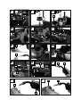
z Assembling the welding
mask
Place the dark welding glass
21
into
the mask with the writing on the top
20
(see Fig. C). The writing on the dark
welding glass
21
must now be visible
from the front of the welding mask.
Push the handle
22
from the inside into
the corresponding notch of the mask,
until it snaps into place (see Fig. D).
Safety instructions / Before use / Assembly

16
GB/IE/NI
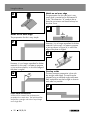
z Inserting the flux-cored
wire
Always unplug the mains
plug from the mains socket prior to each
maintenance task or preparatory work in order
to prevent the risk of an electric shock, injury
or damage.
Please note: Different welding wires will
be needed depending on the application.
Welding wires with a diameter of
0.6 - 1.0 mm can be used with this device.
Feed roll,
welding nozzle
and wire cross-
section must be compatible with one another.
The device is suitable for wire reels weighing
up to maximum 1000 g.
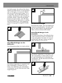
Unlock and open the cover of the wire
feed unit
1
by raising the threaded rod
along the elongated hole.
Unlock the roller unit by turning the roller
mount
29
anti-clockwise (see Fig. F).
Pull the roller mount
29
off the shaft
(see Fig. F).
Please note: Make sure that the end of the
wire does not come loose and cause the roll
to roll out on its own. The end of the wire
may not be released until during assembly.
Completely unpack the flux-cored wire
welding reel
17
, so that it can unrolled
without difficulty. Do not release the wire
end yet (see Fig. G).
Place the wire reel on the shaft. Make
sure that the roll unwinds on the side of
the
31
wire feed guide (see Fig. G).
Place the roll mount
29
back on and
lock it by pressing and turning it clock-
wise (see Fig. G).
Undo the adjustment screw
27
and swing
it upwards (see Fig. H).
Turn the thrust roller unit
28
to the side
(see Fig. I).
Loosen the feed roll holder
30
by turning
it anti-clockwise and pull it upwards and
off (see Fig. J).
On the top of the feed roll
19
, check
whether the appropriate wire thickness is
indicated. If necessary, the feed roll has
to be turned over or replaced. The sup-
plied welding wire (Ø 0.9 mm) must be
used in the feed roll
19
with the specified
wire thickness of Ø 0.9 mm.
The wire
must be positioned in the upper groove!
Erect the feed roll holder
30
again and
screw clockwise direction.
Remove the torch nozzle
9
by turning
it clockwise (see Fig. K).
Unscrew the welding
15
nozzle
(see Fig. K).
Guide the cable assembly
12
away from
the welding device as straight as possi-
ble (place it on the floor).
Take the wire end out of the edge of the
spool (see Fig L).
Trim the wire end with wire scissors or
a diagonal cutter in order to remove
the damaged, bent ends of the wire
(see Fig. L).
Please note: The wire must be kept
under tension the entire time in order to
avoid a releasing and a roll out! There-
fore it is recommended to carry out the
work with an additional person.
Push the flux-cored wire through the wire
feed guide
31
(see Fig. M).
Guide the wire along the feed roll
19
and push it into the cable assembly
holder
32
(see Fig. N).
Swivel the thrust roller unit
28
towards
the feed roll
19
(see Fig. O).
Mount the adjustment
27
screw
(see Fig. O).
Set the counter pressure with the adjust-
ment screw. The welding wire must be
firmly positioned between the thrust roller
and feed roll
19
in the upper guide
without being crushed (see Fig. O).
Switch on the welding device on the
main
5
switch.
Press the torch button
11
.
Assembly

17
GB/IE/NI
Now the wire feed system pushes the
welding wire through the cable assembly
12
and the torch
10
.
As soon as 1 – 2 cm of the wire
protrudes from the torch neck
33
,
release the torch
11
button again
(see Fig. P).
Switch off the welding device on the
main switch.
Screw the welding nozzle
15
back on.
Make sure that the welding nozzle
15
matches the diameter of the welding
wire used (see Fig. Q). When using the
delivered welding wire (Ø 0.9 mm),
the welding nozzle with the
15
labelling
0.9 mm must be used.
Push the torch nozzle
9
back on to the
torch neck with a turn tot the right
33
(see Fig. R).
Always unplug the mains
plug from the socket prior to each mainten-
ance task or preparatory work in order to
prevent the risk of an electric shock, injury or
damage.
z Using the device
z Switching the device on
and off
Switch the welding device on and off
on the main
5
switch. If you do not
intend to use the welding device for an
extended period, remove the plug from
the power socket. This is the only way to
completely de-energise the device
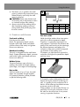
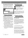
z Setting the welding current
The switches on the front of the welding de-
vice can be used to set the desired welding
currents.
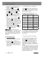
The rotaryswitch for welding current setting
7
on the front of the welding machine can
be used to set the desired welding currents.
The corresponding settings can be found in
the following table.
Voltage (V) Wire feed
Welding
current
A 2 – 4 25 – 75
B 3 – 5 55 – 85
C 3 – 6 60 – 100
D 4 – 8 65 – 105
E 5 – 9 75 – 110
F 5 – 10 80 – 115
G 5 – 10 85 – 120
The necessary welding current depends on
the welding wire diameter used, the material
thickness and the desired penetration depth.
z Setting the wire feed
In order to generate a constant arc, the
setting wheel for the wire feed
8
can be
used to fine-tune the wire feed. You are
recommended to use a setting in the middle
range to start with, and then reduce or
increase the speed as required.
The necessary welding current depends on
the welding wire diameter used, the material
thickness and the desired penetration depth.
Similarly, the gaps to be bridged between
the workpieces to be welded must be ob-
served.
Overload protection
The welding device is protected against
overheating by means of an automatic
protection device (thermostat with automatic
restart). The protective device interrupts
the overload of the current circuit and the
Assembly / Using the device

18
GB/IE/NI
yellow overload protection control lamp
6
illuminates.
Allow the device to cool down (approx.
15 minutes) for the activation of the
protection device. As soon as the yellow
overload protection control lamp
6
goes
out, the device is ready for operation
again.
Welding mask
HEALTH HAZARD!
If you do not use the welding mask, harmful
UV radiation and heat emitted by the electric
arc could damage your eyes.
Always use the welding mask for welding
work.
z Welding
RISK OF BURNS!
Welded workpieces are very hot and can
cause burns.
Always use pliers to move hot, welded
workpieces.
Please proceed as follows once
you have electrically connected the
welding device:
Connect the earth cable to
4
the
workpiece that is to be welded using
the earth terminal. Please ensure good
electrical conductivity.
The area to be welded on the workpiece
must be free of rust and paint.
Choose the desired welding current and
wire feed depending on the welding
wire diameter, material thickness and
desired penetration depth.
Switching the device on.
Hold the welding mask
23
in front of
your face and guide the torch nozzle
9
to the position on the workpiece that is to
be welded.
Press the torch button
11
, in order to
generate an arc. Once the electric arc is
burning, the device feeds wire into the
weld pool.
If the welding lens is big enough, the
torch
10
is slowly guided along the
desired edge. The distance between the
torch nozzle and workpiece should be as
small as possible (it must not be greater
than 10 mm).
If necessary, oscillate a little to increase
the size of the weld pool. For inexperi-
enced welders, it is often difficult initially
to create a decent electric arc. To do so,
the welding current and wire feed rate
must be set correctly.
You can work out the ideal settings for
the welding current and the wire feed
rate by carrying out trial welds on a test
piece. A properly set electric arc has a
mild, uniform buzzing sound.
The penetration depth (corresponds to
the depth of the welding seam in the
material) should be as deep as possible
without allowing the welding pool to fall
through the workpiece.
Reduce the wire feed rate in case of a
rough or hard rattle or switch to a higher
power level (increase welding current).
If the wire feed rate is too high and/or
the welding current too low, the welding
wire will not melt properly. Consequently,
the welding wire repeatedly dips in the
welding pool as far as the workpiece.
A quiet, muffled sound with a flickering
electric arc indicates the wire feed is
too low.
Increase the wire feed rate or switch to
a lower welding current. If the welding
current is too high, the wire will melt
before it even reaches the weld bed.
This results in droplet formation on the
welding wire as well as splash and an
irregular electric arc.
The slag can only be removed from
the seam once it has cooled down.
To continue welding an an interrupted
seam:
First remove the slag at the starting point.
Using the device

19
GB/IE/NI
The electric arc is ignited in the weld
groove, guided to the continuation point,
melted properly and finally the weld
seam is continued.
CAUTION: Please note that the torch
must always has to be placed on down
an insulated surface after welding.
Always switch off the welding device
after completing welding work and
during breaks and pull the plug from
the mains socket.
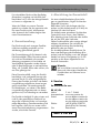
z Create a weld seam
Forehand welding
Push the torch forwards.
Result: The penetration depth is lower,
broader weld width, flatter weld bead
(visible surface of the seam) and greater
fusion error tolerance.
Backhand welding
The torch is dragged from the weld seam.
Result: Greater penetration depth, narrower
weld width, higher weld bead and lower
fusion error tolerance.
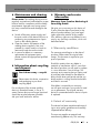
Welded joints
There are two-basic types of joints in
welding: Butt welds and angle welding
(outer edge, inner edge and overlapping).
Butt welds
With butt welds of up to 2 mm, the weld
edges are completely brought together.
For greater thicknesses, please proceed
as per the following table:
S
S = 1-3 mm 3-4 mm 4-6 mm
d = surface 0.5-1.5- mm 1.5-2.5 mm 2-3 mm
d = vertical 1-1.5- mm 1.5-2.5 mm 2-3 mm
d = front
surface
1-2 mm 2-3 mm 3-4 mm
Flat butt welds
Welds should be made without interruption
and with a sufficient penetration depth.
Therefore, it is extremely important to be
well prepared. The factors that influence the
quality of the weld result are: the amperage,
the distance between weld edges, the
inclination of the torch and the correspond-
ing diameter of the welding wire.
The steeper you hold the torch against the
workpiece, the higher the penetration depth
and vice versa.
T
To forestall or reduce deformations that can
happen during the material hardening pro-
cess, it is good to fix the workpiece with a
device. Avoid stiffening the welded structure
to prevent cracks in the weld.
These problems can be avoided if there is a
possibility of turning the workpiece so that
the weld can be carried out in two passes
running in opposite directions.
Using the device

20
GB/IE/NI
U
Welds on the outer edge
The preparation for this is very simple.
V
However, it is no longer expedient for thicker
materials. In this case, it is better to prepare
a joint as shown below, in which the edge of
the plate is angled.
W
Fillet weld connections
A fillet weld is created if the workpieces are
perpendicular to each other. The weld should be
shaped like a triangle with sides of equal length
and a slight fillet.
Welds on an inner edge
The preparation for this weld joint is very
simply and is carried out for thicknesses of
5 mm. The dimension “d” needs to be re-
duced to a minimum and should always be
less than 2 mm.
X
However, it is no longer expedient for thicker
materials. In this case, it is better to prepare
a joint as shown in Figure W, in which the
edge of the plate is angled.
Y
Overlap welds
The most common preparation is that with
the straight weld edges. The weld can be
released using a standard angle weld seam.
Both workpieces must be brought as close to
each other as possible.
Z
Using the device
Seite wird geladen ...
Seite wird geladen ...
Seite wird geladen ...
Seite wird geladen ...
Seite wird geladen ...
Seite wird geladen ...
Seite wird geladen ...
Seite wird geladen ...
Seite wird geladen ...
Seite wird geladen ...
Seite wird geladen ...
Seite wird geladen ...
Seite wird geladen ...
Seite wird geladen ...
Seite wird geladen ...
Seite wird geladen ...
Seite wird geladen ...
Seite wird geladen ...
Seite wird geladen ...
Seite wird geladen ...
Seite wird geladen ...
Seite wird geladen ...
Seite wird geladen ...
Seite wird geladen ...
Seite wird geladen ...
-
 1
1
-
 2
2
-
 3
3
-
 4
4
-
 5
5
-
 6
6
-
 7
7
-
 8
8
-
 9
9
-
 10
10
-
 11
11
-
 12
12
-
 13
13
-
 14
14
-
 15
15
-
 16
16
-
 17
17
-
 18
18
-
 19
19
-
 20
20
-
 21
21
-
 22
22
-
 23
23
-
 24
24
-
 25
25
-
 26
26
-
 27
27
-
 28
28
-
 29
29
-
 30
30
-
 31
31
-
 32
32
-
 33
33
-
 34
34
-
 35
35
-
 36
36
-
 37
37
-
 38
38
-
 39
39
-
 40
40
-
 41
41
-
 42
42
-
 43
43
-
 44
44
-
 45
45


Parkside PFDS 120 A2 Translation Of The Original Instructions
- Typ
- Translation Of The Original Instructions
in anderen Sprachen
- English: Parkside PFDS 120 A2
Verwandte Artikel
-
Parkside PISG 120 B3 Benutzerhandbuch
-
Parkside PFDS 33 B2 Assembly, Operating And Safety Instructions
-
Parkside PISG 100 A1 Benutzerhandbuch
-
-
-
-
-
-
-
Andere Dokumente
-
Ferm WEM1042 Arc Welder Benutzerhandbuch
-
Einhell Blue BT-EW 150 V Bedienungsanleitung
-
GYS NEOPULSE 320 C Bedienungsanleitung
-
Cebora 532 Bravo 165 combi Benutzerhandbuch
-
Prima MIG 205AL Benutzerhandbuch
-
Scheppach WSE850 Benutzerhandbuch
-
-
-
Abicor Binzel PP PLUS ABIMIG AT LW Bedienungsanleitung